EP0664396A1 - Compresseur du type à spirales - Google Patents
Compresseur du type à spirales Download PDFInfo
- Publication number
- EP0664396A1 EP0664396A1 EP95100905A EP95100905A EP0664396A1 EP 0664396 A1 EP0664396 A1 EP 0664396A1 EP 95100905 A EP95100905 A EP 95100905A EP 95100905 A EP95100905 A EP 95100905A EP 0664396 A1 EP0664396 A1 EP 0664396A1
- Authority
- EP
- European Patent Office
- Prior art keywords
- scroll
- fixed scroll
- outlet
- flange
- compressor according
- Prior art date
- Legal status (The legal status is an assumption and is not a legal conclusion. Google has not performed a legal analysis and makes no representation as to the accuracy of the status listed.)
- Granted
Links
- 230000006835 compression Effects 0.000 claims abstract description 16
- 238000007906 compression Methods 0.000 claims abstract description 16
- 238000005553 drilling Methods 0.000 claims description 2
- 239000002184 metal Substances 0.000 claims 4
- 239000003507 refrigerant Substances 0.000 description 11
- 238000004512 die casting Methods 0.000 description 5
- 238000003754 machining Methods 0.000 description 4
- 238000000034 method Methods 0.000 description 3
- 238000000465 moulding Methods 0.000 description 3
- 229910000838 Al alloy Inorganic materials 0.000 description 1
- 230000004323 axial length Effects 0.000 description 1
- 238000007599 discharging Methods 0.000 description 1
- 230000002093 peripheral effect Effects 0.000 description 1
Images


Classifications
-
- F—MECHANICAL ENGINEERING; LIGHTING; HEATING; WEAPONS; BLASTING
- F04—POSITIVE - DISPLACEMENT MACHINES FOR LIQUIDS; PUMPS FOR LIQUIDS OR ELASTIC FLUIDS
- F04C—ROTARY-PISTON, OR OSCILLATING-PISTON, POSITIVE-DISPLACEMENT MACHINES FOR LIQUIDS; ROTARY-PISTON, OR OSCILLATING-PISTON, POSITIVE-DISPLACEMENT PUMPS
- F04C18/00—Rotary-piston pumps specially adapted for elastic fluids
- F04C18/02—Rotary-piston pumps specially adapted for elastic fluids of arcuate-engagement type, i.e. with circular translatory movement of co-operating members, each member having the same number of teeth or tooth-equivalents
-
- F—MECHANICAL ENGINEERING; LIGHTING; HEATING; WEAPONS; BLASTING
- F01—MACHINES OR ENGINES IN GENERAL; ENGINE PLANTS IN GENERAL; STEAM ENGINES
- F01C—ROTARY-PISTON OR OSCILLATING-PISTON MACHINES OR ENGINES
- F01C21/00—Component parts, details or accessories not provided for in groups F01C1/00 - F01C20/00
- F01C21/10—Outer members for co-operation with rotary pistons; Casings
-
- F—MECHANICAL ENGINEERING; LIGHTING; HEATING; WEAPONS; BLASTING
- F01—MACHINES OR ENGINES IN GENERAL; ENGINE PLANTS IN GENERAL; STEAM ENGINES
- F01C—ROTARY-PISTON OR OSCILLATING-PISTON MACHINES OR ENGINES
- F01C1/00—Rotary-piston machines or engines
- F01C1/02—Rotary-piston machines or engines of arcuate-engagement type, i.e. with circular translatory movement of co-operating members, each member having the same number of teeth or tooth-equivalents
- F01C1/0207—Rotary-piston machines or engines of arcuate-engagement type, i.e. with circular translatory movement of co-operating members, each member having the same number of teeth or tooth-equivalents both members having co-operating elements in spiral form
- F01C1/0215—Rotary-piston machines or engines of arcuate-engagement type, i.e. with circular translatory movement of co-operating members, each member having the same number of teeth or tooth-equivalents both members having co-operating elements in spiral form where only one member is moving
-
- F—MECHANICAL ENGINEERING; LIGHTING; HEATING; WEAPONS; BLASTING
- F04—POSITIVE - DISPLACEMENT MACHINES FOR LIQUIDS; PUMPS FOR LIQUIDS OR ELASTIC FLUIDS
- F04C—ROTARY-PISTON, OR OSCILLATING-PISTON, POSITIVE-DISPLACEMENT MACHINES FOR LIQUIDS; ROTARY-PISTON, OR OSCILLATING-PISTON, POSITIVE-DISPLACEMENT PUMPS
- F04C18/00—Rotary-piston pumps specially adapted for elastic fluids
- F04C18/02—Rotary-piston pumps specially adapted for elastic fluids of arcuate-engagement type, i.e. with circular translatory movement of co-operating members, each member having the same number of teeth or tooth-equivalents
- F04C18/0207—Rotary-piston pumps specially adapted for elastic fluids of arcuate-engagement type, i.e. with circular translatory movement of co-operating members, each member having the same number of teeth or tooth-equivalents both members having co-operating elements in spiral form
- F04C18/0215—Rotary-piston pumps specially adapted for elastic fluids of arcuate-engagement type, i.e. with circular translatory movement of co-operating members, each member having the same number of teeth or tooth-equivalents both members having co-operating elements in spiral form where only one member is moving
-
- F—MECHANICAL ENGINEERING; LIGHTING; HEATING; WEAPONS; BLASTING
- F04—POSITIVE - DISPLACEMENT MACHINES FOR LIQUIDS; PUMPS FOR LIQUIDS OR ELASTIC FLUIDS
- F04C—ROTARY-PISTON, OR OSCILLATING-PISTON, POSITIVE-DISPLACEMENT MACHINES FOR LIQUIDS; ROTARY-PISTON, OR OSCILLATING-PISTON, POSITIVE-DISPLACEMENT PUMPS
- F04C18/00—Rotary-piston pumps specially adapted for elastic fluids
- F04C18/02—Rotary-piston pumps specially adapted for elastic fluids of arcuate-engagement type, i.e. with circular translatory movement of co-operating members, each member having the same number of teeth or tooth-equivalents
- F04C18/0207—Rotary-piston pumps specially adapted for elastic fluids of arcuate-engagement type, i.e. with circular translatory movement of co-operating members, each member having the same number of teeth or tooth-equivalents both members having co-operating elements in spiral form
- F04C18/0246—Details concerning the involute wraps or their base, e.g. geometry
- F04C18/0253—Details concerning the base
-
- Y—GENERAL TAGGING OF NEW TECHNOLOGICAL DEVELOPMENTS; GENERAL TAGGING OF CROSS-SECTIONAL TECHNOLOGIES SPANNING OVER SEVERAL SECTIONS OF THE IPC; TECHNICAL SUBJECTS COVERED BY FORMER USPC CROSS-REFERENCE ART COLLECTIONS [XRACs] AND DIGESTS
- Y10—TECHNICAL SUBJECTS COVERED BY FORMER USPC
- Y10T—TECHNICAL SUBJECTS COVERED BY FORMER US CLASSIFICATION
- Y10T29/00—Metal working
- Y10T29/49—Method of mechanical manufacture
- Y10T29/49229—Prime mover or fluid pump making
- Y10T29/49236—Fluid pump or compressor making
- Y10T29/4924—Scroll or peristaltic type
Definitions
- This invention relates to a scroll type compressor to be employed, for example, in an automotive air conditioner. More particularly, the present invention relates to the structure of an outlet for discharging a compressed gas from the housing of the compressor to an external piping.
- a typical scroll type compressor is provided with a housing in which a fixed scroll is accommodated.
- the fixed scroll has a base plate and a spiral element.
- a rotary shaft is supported at the front side of the housing via a bearing, and an eccentric pin is attached to the inner end of the rotary shaft.
- a movable scroll having a boss at the front surface of its base plate is provided. The boss engages the eccentric pin via a bushing and a bearing so as to rotate relative to the eccentric pin.
- the spiral element of the movable scroll meshes with the spiral element of the fixed scroll at staggered angles.
- An anti-rotation mechanism is interposed between the movable scroll and a fixed pressure receiving wall of the housing. This mechanism prohibits rotation of the movable scroll and allows orbital movement thereof.
- Compression chambers are defined between the spiral element of the fixed scroll and that of the movable scroll. The volume of the compression chambers or pockets is reduced as they are moved from the periphery toward the center under the orbital movement of the movable scroll. Thus, a refrigerant gas is compressed in the pockets.
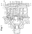
- a rear housing 42 is fixed to the rear side of a base plate 41a of a fixed scroll 41.
- the rear housing 42 is provided with a discharge chamber 43 for temporarily storing the high-pressure refrigerant gas discharged through a discharge port 41c of the base plate 41a so as to moderate surging of the gas.
- An outlet flange 42a is formed integrally with the rear housing 42 on the outer circumferential wall thereof.
- the outlet flange 42a has an outlet 42b for leading the gas in the discharge chamber 43 to an external refrigerant piping.
- the outlet flange 42a is formed on the outer peripheral wall of the rear housing 42. Accordingly, the depth L of the rear housing 42 in the axial direction of the compressor cannot be made smaller than the diameter D of the outlet flange 42a. This undesirably lengthens the compressor.
- a compressor according to the present invention has a fixed scroll disposed in a housing and also a movable scroll disposed to oppose to the fixed scroll so as to define a compression chamber between these two scrolls.
- the gas introduced through an inlet to a suction chamber is compressed in the compression chamber and then discharged through a discharge port into the discharge chamber to be exhausted through an outlet to the outside of the compressor.
- the discharge chamber is at least partly defined in the fixed scroll.
- the outlet flange protrudes from the fixed scroll outward and is provided with an outlet communicating to the discharge chamber.
- a fixed scroll 1 serves as a center housing 1d, and a front housing 2 is fixed to the fixed scroll 1.
- a rotary shaft 3 is rotatably supported via a bearing 3a in the front housing 2.
- An eccentric pin 4 is secured to the rotary shaft 3.
- a balancer weight 5 and a bushing 6 are rotatably attached to the eccentric pin 4.
- a movable scroll 7, which meshes with the fixed scroll 1, is rotatably supported via a radial bearing 8 by the bushing 6.
- These too scrolls 1, 7 are provided with base plates 1a, 7a and spiral elements 1b, 7b formed integrally with the associated base plates, respectively.
- the fixed base plate 1a is located at a rear part of the compressor, whereas the movable base plate 7a is located substantially at the center of the compressor.
- a boss 7c, in which the bushing 6 is to be fitted, is formed integrally with the movable base plate 7a at the front surface thereof.
- a plurality of compression chambers P are defined between the base plates 1a, 7a and the spiral elements 1b,7b.
- the front surface of the movable base plate 7a comprises a movable pressure receiving wall 7d.
- a fixed pressure receiving wall 2a is formed on the inner surface of the front housing 2.
- An anti-rotation mechanism K is interposed between these two pressure receiving walls 2a, 7d. This mechanism K prohibits rotation of the movable scroll 7 about its own axis, but permits orbital movement around the axis of the rotary shaft 3.
- the anti-rotation mechanism K has a plurality of recesses 2b (four recesses in this embodiment) formed on the fixed pressure receiving wall 2a.
- This mechanism K also has a plurality of recesses 7e formed on the movable base plate 7a, which are offset a predetermined distance from the recesses 2b respectively.
- a ring 9 is interposed between these pressure receiving walls 2a, 7d.
- a plurality of pins 10 are inserted into the ring 9, and the pins 10 are engaged with the inner circumferences of the recesses 2b, 7e, respectively.
- a plurality of elements 9a are formed integrally with the ring 9 on the front side and rear side thereof at a predetermined interval. These elements 9a are directed to transmit the force resulting from the pressure of the compressed refrigerant gas from the movable pressure receiving wall 7d to the fixed pressure receiving wall 2a.
- An inlet (not shown) is defined in the front housing 2, and a suction chamber 11 is defined between the movable scroll 7 and the inner surface of the front housing 2.
- a rear housing 12 is fixed to the rear surface of the fixed base plate 1a.
- a recess 31 is defined on the rear surface of the fixed base plate 1a.
- a discharge chamber 13 includes this recess 31 and an inner space 12a of the rear housing 12.
- a discharge port 1c is formed in the fixed base plate 1a, and a discharge valve 14 for opening and closing the discharge port 1c is provided in the discharge chamber 13.
- Thin discharge valve 14 is fixed to the base plate 1a together with a retainer 15 by a bolt 16.
- An outlet flange 1e is formed integrally with the fixed base plate 1a on the outer circumference thereof.
- the outlet flange 1e has an outlet 1f formed adjacent to the recess 31, and the outlet 1f communicates via the recess 31 to the discharge chamber 13.
- An external refrigerant piping 34 can be connected to the outlet flange 1e.
- the fixed scroll 1 is molded together with the center housing 1d by means of hot chamber type die-casting method. In die-casting the fixed scroll 1, a molten aluminum alloy is poured through a gate 22 into a cavity 23 defined between a pair of molding dies 20,21, as shown in Fig. 3.
- the gate 22 has an inner diameter suitable for forming the outlet flange 1e. Accordingly, the columnar section molded in the gate 22 can be utilized as the outlet flange 1e.
- the outlet 1f can be formed through this outlet flange 1e by drilling and the like.
- the movable scroll 7 makes an orbital movement along a circular orbit having an orbital radius substantially represented by subtracting "r” from “R” (R-r), where "R” represents the diameter of the recesses 2b,7e and "r” represents the diameter of the pins 10.
- the refrigerant gas is introduced to the suction chamber 11 through the inlet (not shown) under the orbital movement of the movable scroll 7 and then allowed to flow into the compression chambers P defined between these two scrolls 1, 7.
- the compression chambers P converge toward the centers of the spiral elements 1b, 7b as their volumes are reduced under the orbital movement of the movable scroll 7.
- the refrigerant gas is compressed in the compression chambers P and discharged through the discharge port 1c into the discharge chamber 13.
- the refrigerant gas in the discharge chamber 13 is fed through the outlet 1f to the external refrigerant piping 34.
- the pressure of the refrigerant gas in the compression chambers P acts upon the movable scroll 7.
- the force resulting from this pressure is transmitted from the movable pressure receiving wall 7d via the pressure receiving elements 9a of the ring 9 to the fixed pressure receiving wall 2a.
- the outlet flange 1e is formed integrally with the fixed base plate 1a on the outer circumference thereof. Accordingly, the size of the rear housing 12 along the axis of the compressor can be reduced compared with the case where the outlet flange is formed on the outer circumference or rear surface of the rear housing 12. Thus, the compressor can be shortened and lightened, which is desirable given the limited engine space of an automobile.
- a columnar section formed in a gate 22 for die-casting a fixed scroll 1 is utilized for forming the outlet flange 1e. Accordingly, there is no need of providing any special cavity for forming the outlet flange 1e in the dies.
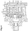
- an inlet flange 1g is formed integrally with a center housing 1d on the outer circumference thereof at a front part.
- An inlet 1h communicating to a suction chamber 11 is formed in the flange 1g by post-machining.
- the length of the suction flow path in the compressor and also the loss of suction gas can be reduced.
- the shape or the front housing 2 can be simplified, reducing the number of machining steps.
- FIG. 5 A third embodiment of the present invention will be described referring to Fig. 5.
- an outlet flange 1e and an inlet flange 1g are formed adjacent to each other at different heights on the rear part of a center housing 1d.
- the inlet flange 1g is formed utilizing a columnar section corresponding to the gate of the mold.
- the flanges 1e, 1g are formed adjacent to each other, machining of the inlet and outlet can further be facilitated as compared with the second embodiment.
- the height of the flange 1e and that of the flange 1g may be equal.
- FIG. 6 A fourth embodiment of the present invention will be described referring to Fig. 6.
- the rear housing is omitted, and a discharge chamber 13 is formed within a fixed base plate 1a.
- An outlet flange 1e is formed on the outer circumference of the base plate 1a as in the first embodiment and is provided with an outlet 1f communicating with the discharge chamber 13.
- the valve 14 for opening and closing the discharge port 1c is omitted.
- the entire axial length of the compressor can further be reduced compared with the first, second, and third embodiments.
- a scroll type compressor has a fixed scroll in a housing and a movable scroll opposed to the fixed scroll to define a compression chamber with the fixed scroll. Gas introduced into a suction chamber via an inlet is compressed in the compression chamber and then is discharged to a discharge, chamber via a discharge port to exhaust the compressed gas from an outlet to the outside of the compressor in accordance with the circular movement of the movable scroll. A part of the discharge chamber is defined in the fixed scroll. An outlet flange protrudes from the fixed scroll. The outlet flange includes the outlet which communicates with the discharge chamber.
Landscapes
- Engineering & Computer Science (AREA)
- Mechanical Engineering (AREA)
- General Engineering & Computer Science (AREA)
- Rotary Pumps (AREA)
Applications Claiming Priority (2)
| Application Number | Priority Date | Filing Date | Title |
|---|---|---|---|
| JP6006650A JP3017007B2 (ja) | 1994-01-25 | 1994-01-25 | スクロール型圧縮機 |
| JP6650/94 | 1994-01-25 |
Publications (2)
| Publication Number | Publication Date |
|---|---|
| EP0664396A1 true EP0664396A1 (fr) | 1995-07-26 |
| EP0664396B1 EP0664396B1 (fr) | 1997-12-17 |
Family
ID=11644261
Family Applications (1)
| Application Number | Title | Priority Date | Filing Date |
|---|---|---|---|
| EP95100905A Expired - Lifetime EP0664396B1 (fr) | 1994-01-25 | 1995-01-24 | Compresseur du type à spirales et procédé pour produire une spirale stationnaire du dit compresseur. |
Country Status (5)
| Country | Link |
|---|---|
| US (1) | US5531579A (fr) |
| EP (1) | EP0664396B1 (fr) |
| JP (1) | JP3017007B2 (fr) |
| KR (1) | KR100310922B1 (fr) |
| DE (1) | DE69501214T2 (fr) |
Cited By (1)
| Publication number | Priority date | Publication date | Assignee | Title |
|---|---|---|---|---|
| EP0899460A3 (fr) * | 1997-08-29 | 1999-05-06 | Denso Corporation | Compresseur à spirale |
Families Citing this family (4)
| Publication number | Priority date | Publication date | Assignee | Title |
|---|---|---|---|---|
| JP3718758B2 (ja) * | 1998-12-04 | 2005-11-24 | 株式会社日立製作所 | スクロール流体機械 |
| KR101720611B1 (ko) | 2013-11-15 | 2017-03-28 | 삼성에스디아이 주식회사 | 이차 전지 |
| JP6305833B2 (ja) * | 2014-06-05 | 2018-04-04 | 三菱重工オートモーティブサーマルシステムズ株式会社 | スクロール圧縮機 |
| DE102020211391A1 (de) | 2020-09-10 | 2022-03-10 | Brose Fahrzeugteile SE & Co. Kommanditgesellschaft, Würzburg | Scrollverdichter für Kältemittel einer Fahrzeugklimaanlage |
Citations (7)
| Publication number | Priority date | Publication date | Assignee | Title |
|---|---|---|---|---|
| US4908077A (en) * | 1987-09-04 | 1990-03-13 | Oshida Patent Agency | Scroll made of aluminum alloy |
| EP0457603A1 (fr) * | 1990-05-18 | 1991-11-21 | Sanden Corporation | Appareil de déplacement de fluide à spirales |
| EP0513827A1 (fr) * | 1991-05-15 | 1992-11-19 | Sanden Corporation | Appareil de déplacement de fluide à spirales avec méchanisme de contrôle de capacité |
| US5173042A (en) * | 1991-11-04 | 1992-12-22 | General Motors Corporation | Scroll compressor and discharge valve |
| EP0520431A2 (fr) * | 1991-06-27 | 1992-12-30 | Kabushiki Kaisha Toyoda Jidoshokki Seisakusho | Compresseur du type à volutes |
| WO1993023671A1 (fr) * | 1992-05-11 | 1993-11-25 | Ford Motor Company Limited | Compresseur helicoidal |
| US5290161A (en) * | 1993-06-02 | 1994-03-01 | General Motors Corporation | Control system for a clutchless scroll type fluid material handling machine |
Family Cites Families (5)
| Publication number | Priority date | Publication date | Assignee | Title |
|---|---|---|---|---|
| JPS5990789A (ja) * | 1982-11-16 | 1984-05-25 | Nippon Soken Inc | スクロ−ル型ポンプ |
| JPS6444386U (fr) * | 1987-09-10 | 1989-03-16 | ||
| US4811471A (en) * | 1987-11-27 | 1989-03-14 | Carrier Corporation | Method of assembling scroll compressors |
| KR920010733B1 (ko) * | 1988-06-28 | 1992-12-14 | 마쯔시다덴기산교 가부시기가이샤 | 스크로울압축기 |
| US5392512A (en) * | 1993-11-02 | 1995-02-28 | Industrial Technology Research Institute | Method for fabricating two-piece scroll members by diecasting |
-
1994
- 1994-01-25 JP JP6006650A patent/JP3017007B2/ja not_active Expired - Fee Related
-
1995
- 1995-01-17 KR KR1019950000657A patent/KR100310922B1/ko not_active Expired - Fee Related
- 1995-01-23 US US08/376,839 patent/US5531579A/en not_active Expired - Lifetime
- 1995-01-24 EP EP95100905A patent/EP0664396B1/fr not_active Expired - Lifetime
- 1995-01-24 DE DE69501214T patent/DE69501214T2/de not_active Expired - Fee Related
Patent Citations (7)
| Publication number | Priority date | Publication date | Assignee | Title |
|---|---|---|---|---|
| US4908077A (en) * | 1987-09-04 | 1990-03-13 | Oshida Patent Agency | Scroll made of aluminum alloy |
| EP0457603A1 (fr) * | 1990-05-18 | 1991-11-21 | Sanden Corporation | Appareil de déplacement de fluide à spirales |
| EP0513827A1 (fr) * | 1991-05-15 | 1992-11-19 | Sanden Corporation | Appareil de déplacement de fluide à spirales avec méchanisme de contrôle de capacité |
| EP0520431A2 (fr) * | 1991-06-27 | 1992-12-30 | Kabushiki Kaisha Toyoda Jidoshokki Seisakusho | Compresseur du type à volutes |
| US5173042A (en) * | 1991-11-04 | 1992-12-22 | General Motors Corporation | Scroll compressor and discharge valve |
| WO1993023671A1 (fr) * | 1992-05-11 | 1993-11-25 | Ford Motor Company Limited | Compresseur helicoidal |
| US5290161A (en) * | 1993-06-02 | 1994-03-01 | General Motors Corporation | Control system for a clutchless scroll type fluid material handling machine |
Cited By (3)
| Publication number | Priority date | Publication date | Assignee | Title |
|---|---|---|---|---|
| EP0899460A3 (fr) * | 1997-08-29 | 1999-05-06 | Denso Corporation | Compresseur à spirale |
| US6152713A (en) * | 1997-08-29 | 2000-11-28 | Denso Corporation | Scroll type compressor |
| EP1418337A3 (fr) * | 1997-08-29 | 2004-06-16 | Denso Corporation | Compresseur à spirales |
Also Published As
| Publication number | Publication date |
|---|---|
| DE69501214D1 (de) | 1998-01-29 |
| DE69501214T2 (de) | 1998-05-07 |
| JPH07208355A (ja) | 1995-08-08 |
| KR950033095A (ko) | 1995-12-22 |
| US5531579A (en) | 1996-07-02 |
| KR100310922B1 (ko) | 2002-06-20 |
| EP0664396B1 (fr) | 1997-12-17 |
| JP3017007B2 (ja) | 2000-03-06 |
Similar Documents
| Publication | Publication Date | Title |
|---|---|---|
| EP0342057B1 (fr) | Appareil à volutes pour fluides | |
| EP0012616B1 (fr) | Compresseur à fluide du type à spirales imbriquées | |
| EP1188928B1 (fr) | Compresseurs à spirale | |
| EP0665921B1 (fr) | Appareil a helices a chute de pression reduite a l'entree | |
| EP0656477B1 (fr) | Compresseur du type à spirales | |
| CA1259971A (fr) | Dispositif du type a volutes avec organes spiraux perfectionnes pour le pompage de fluides | |
| US5090880A (en) | Scroll compressor with discharge valves | |
| EP1026402A2 (fr) | Compresseur à spirales | |
| US5037279A (en) | Scroll fluid machine having wrap start portion with thick base and thin tip | |
| US4432708A (en) | Scroll type fluid displacement apparatus with pressure communicating passage between pockets | |
| US5540571A (en) | Scroll-type compressor having bolted housings | |
| EP0648932B1 (fr) | Compresseur à spirales | |
| US4411604A (en) | Scroll-type fluid displacement apparatus with cup shaped casing | |
| EP0520431B1 (fr) | Compresseur du type à volutes | |
| US5531579A (en) | Scroll type compressor | |
| US6247910B1 (en) | Scroll type compressor which requires no flange portions or holes for solely positioning purposes | |
| EP0279646B1 (fr) | Compresseur à volutes imbriquées | |
| EP0806569B1 (fr) | Compresseur à spirales | |
| US5478223A (en) | Scroll type compressor having reaction force transmission and rotation prevention for the moveable scroll | |
| EP0797003A1 (fr) | Dispositif d'accouplement du type Oldham pour appareil de déplacement de fluides à spirales | |
| EP0502513B1 (fr) | Compresseur à volutes | |
| JPH07158571A (ja) | スクロール型圧縮機 | |
| US5395223A (en) | Scroll type compressor having communication passage means with lubricating arrangement associated therewith | |
| US5920985A (en) | Method of manufacturing a movable scroll element | |
| US12209583B2 (en) | Scroll compressor |
Legal Events
| Date | Code | Title | Description |
|---|---|---|---|
| PUAI | Public reference made under article 153(3) epc to a published international application that has entered the european phase |
Free format text: ORIGINAL CODE: 0009012 |
|
| AK | Designated contracting states |
Kind code of ref document: A1 Designated state(s): DE FR GB IT |
|
| 17P | Request for examination filed |
Effective date: 19950707 |
|
| 17Q | First examination report despatched |
Effective date: 19960506 |
|
| GRAG | Despatch of communication of intention to grant |
Free format text: ORIGINAL CODE: EPIDOS AGRA |
|
| RAP1 | Party data changed (applicant data changed or rights of an application transferred) |
Owner name: DENSO CORPORATION Owner name: KABUSHIKI KAISHA TOYODA JIDOSHOKKI SEISAKUSHO |
|
| GRAG | Despatch of communication of intention to grant |
Free format text: ORIGINAL CODE: EPIDOS AGRA |
|
| GRAH | Despatch of communication of intention to grant a patent |
Free format text: ORIGINAL CODE: EPIDOS IGRA |
|
| GRAH | Despatch of communication of intention to grant a patent |
Free format text: ORIGINAL CODE: EPIDOS IGRA |
|
| GRAA | (expected) grant |
Free format text: ORIGINAL CODE: 0009210 |
|
| AK | Designated contracting states |
Kind code of ref document: B1 Designated state(s): DE FR GB IT |
|
| ITF | It: translation for a ep patent filed | ||
| REF | Corresponds to: |
Ref document number: 69501214 Country of ref document: DE Date of ref document: 19980129 |
|
| ET | Fr: translation filed | ||
| PLBE | No opposition filed within time limit |
Free format text: ORIGINAL CODE: 0009261 |
|
| STAA | Information on the status of an ep patent application or granted ep patent |
Free format text: STATUS: NO OPPOSITION FILED WITHIN TIME LIMIT |
|
| 26N | No opposition filed | ||
| PGFP | Annual fee paid to national office [announced via postgrant information from national office to epo] |
Ref country code: GB Payment date: 19990115 Year of fee payment: 5 |
|
| PG25 | Lapsed in a contracting state [announced via postgrant information from national office to epo] |
Ref country code: GB Free format text: LAPSE BECAUSE OF NON-PAYMENT OF DUE FEES Effective date: 20000124 |
|
| GBPC | Gb: european patent ceased through non-payment of renewal fee |
Effective date: 20000124 |
|
| PGFP | Annual fee paid to national office [announced via postgrant information from national office to epo] |
Ref country code: FR Payment date: 20020110 Year of fee payment: 8 |
|
| PGFP | Annual fee paid to national office [announced via postgrant information from national office to epo] |
Ref country code: DE Payment date: 20020227 Year of fee payment: 8 |
|
| PG25 | Lapsed in a contracting state [announced via postgrant information from national office to epo] |
Ref country code: DE Free format text: LAPSE BECAUSE OF NON-PAYMENT OF DUE FEES Effective date: 20030801 |
|
| PG25 | Lapsed in a contracting state [announced via postgrant information from national office to epo] |
Ref country code: FR Free format text: LAPSE BECAUSE OF NON-PAYMENT OF DUE FEES Effective date: 20030930 |
|
| REG | Reference to a national code |
Ref country code: FR Ref legal event code: ST |
|
| PG25 | Lapsed in a contracting state [announced via postgrant information from national office to epo] |
Ref country code: IT Free format text: LAPSE BECAUSE OF NON-PAYMENT OF DUE FEES;WARNING: LAPSES OF ITALIAN PATENTS WITH EFFECTIVE DATE BEFORE 2007 MAY HAVE OCCURRED AT ANY TIME BEFORE 2007. THE CORRECT EFFECTIVE DATE MAY BE DIFFERENT FROM THE ONE RECORDED. Effective date: 20050124 |
|
| PGRI | Patent reinstated in contracting state [announced from national office to epo] |
Ref country code: IT Effective date: 20080301 |
|
| PGFP | Annual fee paid to national office [announced via postgrant information from national office to epo] |
Ref country code: IT Payment date: 20090128 Year of fee payment: 15 |
|
| PG25 | Lapsed in a contracting state [announced via postgrant information from national office to epo] |
Ref country code: IT Free format text: LAPSE BECAUSE OF NON-PAYMENT OF DUE FEES Effective date: 20100124 |