EP0664405B1 - Verbesserungen an Verriegelungsringen - Google Patents
Verbesserungen an Verriegelungsringen Download PDFInfo
- Publication number
- EP0664405B1 EP0664405B1 EP95300277A EP95300277A EP0664405B1 EP 0664405 B1 EP0664405 B1 EP 0664405B1 EP 95300277 A EP95300277 A EP 95300277A EP 95300277 A EP95300277 A EP 95300277A EP 0664405 B1 EP0664405 B1 EP 0664405B1
- Authority
- EP
- European Patent Office
- Prior art keywords
- ring
- component
- limb
- grab
- cylindrical
- Prior art date
- Legal status (The legal status is an assumption and is not a legal conclusion. Google has not performed a legal analysis and makes no representation as to the accuracy of the status listed.)
- Expired - Lifetime
Links
Images


Classifications
-
- F—MECHANICAL ENGINEERING; LIGHTING; HEATING; WEAPONS; BLASTING
- F16—ENGINEERING ELEMENTS AND UNITS; GENERAL MEASURES FOR PRODUCING AND MAINTAINING EFFECTIVE FUNCTIONING OF MACHINES OR INSTALLATIONS; THERMAL INSULATION IN GENERAL
- F16L—PIPES; JOINTS OR FITTINGS FOR PIPES; SUPPORTS FOR PIPES, CABLES OR PROTECTIVE TUBING; MEANS FOR THERMAL INSULATION IN GENERAL
- F16L37/00—Couplings of the quick-acting type
- F16L37/08—Couplings of the quick-acting type in which the connection between abutting or axially overlapping ends is maintained by locking members
- F16L37/084—Couplings of the quick-acting type in which the connection between abutting or axially overlapping ends is maintained by locking members combined with automatic locking
- F16L37/091—Couplings of the quick-acting type in which the connection between abutting or axially overlapping ends is maintained by locking members combined with automatic locking by means of a ring provided with teeth or fingers
-
- F—MECHANICAL ENGINEERING; LIGHTING; HEATING; WEAPONS; BLASTING
- F16—ENGINEERING ELEMENTS AND UNITS; GENERAL MEASURES FOR PRODUCING AND MAINTAINING EFFECTIVE FUNCTIONING OF MACHINES OR INSTALLATIONS; THERMAL INSULATION IN GENERAL
- F16B—DEVICES FOR FASTENING OR SECURING CONSTRUCTIONAL ELEMENTS OR MACHINE PARTS TOGETHER, e.g. NAILS, BOLTS, CIRCLIPS, CLAMPS, CLIPS OR WEDGES; JOINTS OR JOINTING
- F16B13/00—Dowels or other devices fastened in walls or the like by inserting them in holes made therein for that purpose
- F16B13/04—Dowels or other devices fastened in walls or the like by inserting them in holes made therein for that purpose with parts gripping in the hole or behind the reverse side of the wall after inserting from the front
- F16B13/08—Dowels or other devices fastened in walls or the like by inserting them in holes made therein for that purpose with parts gripping in the hole or behind the reverse side of the wall after inserting from the front with separate or non-separate gripping parts moved into their final position in relation to the body of the device without further manual operation
- F16B13/0875—Dowels or other devices fastened in walls or the like by inserting them in holes made therein for that purpose with parts gripping in the hole or behind the reverse side of the wall after inserting from the front with separate or non-separate gripping parts moved into their final position in relation to the body of the device without further manual operation with elastic discs or spring washers anchoring in the hole
-
- F—MECHANICAL ENGINEERING; LIGHTING; HEATING; WEAPONS; BLASTING
- F16—ENGINEERING ELEMENTS AND UNITS; GENERAL MEASURES FOR PRODUCING AND MAINTAINING EFFECTIVE FUNCTIONING OF MACHINES OR INSTALLATIONS; THERMAL INSULATION IN GENERAL
- F16B—DEVICES FOR FASTENING OR SECURING CONSTRUCTIONAL ELEMENTS OR MACHINE PARTS TOGETHER, e.g. NAILS, BOLTS, CIRCLIPS, CLAMPS, CLIPS OR WEDGES; JOINTS OR JOINTING
- F16B19/00—Bolts without screw-thread; Pins, including deformable elements; Rivets
- F16B19/002—Resiliently deformable pins
-
- F—MECHANICAL ENGINEERING; LIGHTING; HEATING; WEAPONS; BLASTING
- F16—ENGINEERING ELEMENTS AND UNITS; GENERAL MEASURES FOR PRODUCING AND MAINTAINING EFFECTIVE FUNCTIONING OF MACHINES OR INSTALLATIONS; THERMAL INSULATION IN GENERAL
- F16B—DEVICES FOR FASTENING OR SECURING CONSTRUCTIONAL ELEMENTS OR MACHINE PARTS TOGETHER, e.g. NAILS, BOLTS, CIRCLIPS, CLAMPS, CLIPS OR WEDGES; JOINTS OR JOINTING
- F16B21/00—Means for preventing relative axial movement of a pin, spigot, shaft or the like and a member surrounding it; Stud-and-socket releasable fastenings
- F16B21/10—Means for preventing relative axial movement of a pin, spigot, shaft or the like and a member surrounding it; Stud-and-socket releasable fastenings by separate parts
- F16B21/16—Means for preventing relative axial movement of a pin, spigot, shaft or the like and a member surrounding it; Stud-and-socket releasable fastenings by separate parts with grooves or notches in the pin or shaft
- F16B21/18—Means for preventing relative axial movement of a pin, spigot, shaft or the like and a member surrounding it; Stud-and-socket releasable fastenings by separate parts with grooves or notches in the pin or shaft with circlips or like resilient retaining devices, i.e. resilient in the plane of the ring or the like; Details
- F16B21/183—Means for preventing relative axial movement of a pin, spigot, shaft or the like and a member surrounding it; Stud-and-socket releasable fastenings by separate parts with grooves or notches in the pin or shaft with circlips or like resilient retaining devices, i.e. resilient in the plane of the ring or the like; Details internal, i.e. with spreading action
Definitions
- This invention relates to grab rings for locking cylindrical components in bores in further components.
- a grab ring in a cylindrical bore for locking a cylindrical component in the bore
- the ring is formed from a spring steel having an outer periphery mounted in a groove encircling the cylindrical bore and an inner peripheral portion which is obliquely angled to bear against the outer periphery of the cylindrical component to be locked in the bore to allow the component to be inserted into the bore and to lock the component against withdrawal from the bore.
- Such grab rings may have resilient fingers projecting from their inner peripheries to engage and grip the component inserted through the ring.
- DE-A-2354185 discloses a partially annular ring of spring material for engaging in a groove in one component and having an angled cross-section with spaced radially projecting fingers formed around its outer periphery to engage in a bore of another component.
- FR-A-2102518 discloses a metal sleeve mounted in a groove in a rod and having projections to engage the surface of a bore in a body in which the end of the rod is to be secured.
- Such rings/sleeves have relatively narrow slots to allow the rings/sleeves to be open to engage over a shaft or a rod on which the ring or sleeve is to be mounted. If the ring is formed from a relatively stiff material to provide an effective grip between two components, it can be difficult to open the ring easily to enable it to be manipulated onto the rod or shaft on which it is to be mounted.
- This invention provides a grab ring for locking a cylindrical component in a bore in another component, the ring being mountable in a groove in the cylindrical component and being formed from spring metal with an L-shaped cross-section, one limb of which is part-cylindrical and the other limb of which extends radially to the part-cylindrical limb, a free edge of the part-cylindrical limb having means extending along the edge to stiffen the ring, and a free edge of the radial limb having gripping means extending along the edge for gripping a surface of the other component, the ring further including a radial slot to allow the ring to be flexed open for location on a component, wherein the ring is formed to provide a hinge about an axis parallel to the ring axis to facilitate opening of the ring for assembly on a component and to bias the ring into its closed position.
- the hinge in the ring is located diametrically opposite the slot.
- the slot extends over only a minor proportion of the circumference of the ring. Typically, the slot may extend over approximately one eighth of the circumference of the ring.
- the gripping means may comprise a multiplicity of teeth formed integrally with the radial limb and projecting outwardly therefrom at an oblique angle to allow a component to slide past the ring in one direction but to be gripped in the opposite direction.
- the mounting means for the ring may include upstanding resilient legs formed at spaced locations around the free edge of the cylindrical limb.
- the ring may be encapsulated in a moulded plastics ring dimensioned to fit in the groove in the component.
- the integral hinge may be formed so that the ring is biassed to snap open or closed from an intermediate position in its travel.
- means may be provided to close the radial slot in the ring once the ring has been assembled on the component.
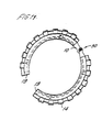
- a grab ring is illustrated for mounting in a groove of a cylindrical component which is intended to be received and locked in a bore of a further component.
- the grab ring comprises an L-shaped cross-section core indicated generally at 10, one limb 11 of which is part cylindrical and the other limb 12 of which extends radially from the part cylindrical component.
- the core is encapsulated in a moulded plastics sleeve 13.
- the free edge of the radial limb 12 is formed with a multiplicity of resilient teeth 14 around its periphery which are angled obliquely to the radial plane of the limb 12 to allow the ring to be slid along a bore in one direction but to resist movement in the opposite direction.
- the free edge of the cylindrical element is formed with spaced obliquely angled legs to provide stiffness in the axial direction.
- the component 16 with the ring assembled on it can then be inserted in a bore 17 in a body 18.
- the obliquely angled teeth 14 allow the ring to slide into the bore but restrict extraction from the bore.
- the ring is formed with a slot 19 part way around its circumference, the length of which is approximately one eighth of the total circumference of the ring.
- the slot permits the ring to be flexed inwardly and outwardly when assembling on a component as illustrated in Figure 3.
- Figures 6 to 10 of the drawings show a similar arrangement except that the plastics moulding in which the metal ring is inserted is omitted leaving the metal element to be inserted directly in a groove in a component.
- the ring of Figure 11 is provided with a hinge point indicated generally at 30 directly opposite the slot to allow the ring to be opened for assembly around a component.
- the plastics sleeve 13 is cut away and the hinge is formed by flattening the metal core 10 in the radial plane and by shaping the flattened portion to provide a fixed hinge axis and which the ring opens and closes.
- the core is shaped so that the ring is biased to snap open or closed from an intermediate position in its travel. In a further arrangement the core is cut away and the hinge is formed in the plastics sleeve.
- a closure may be provided for the radial slot for holding the ring closed.
- a very narrow slot may be provided in the ring and the ends of the ring may be shaped to interengage and lock together.
Landscapes
- Engineering & Computer Science (AREA)
- General Engineering & Computer Science (AREA)
- Mechanical Engineering (AREA)
- Snaps, Bayonet Connections, Set Pins, And Snap Rings (AREA)
- Clamps And Clips (AREA)
Claims (8)
- Verriegelungsring zum Verriegeln eines zylindrischen Bauteils in einer Bohrung in einem anderen Bauteil, wobei der Ring (10) in einer Nut in dem zylindrischen Bauteil montierbar ist und aus federndem Metall mit einem L-förmigen Querschnitt hergestellt ist, dessen einer Schenkel (11) teilzylindrisch ist und dessen anderer Schenkel (12) sich radial zum teilzylindrischen Schenkel erstreckt, wobei eine freie Kante des teilzylindrischen Schenkels entlang der Kante Mittel zum Versteifen des Rings aufweist, und eine freie Kante des radialen Schenkels Verriegelungsmittel (14) aufweist, die sich entlang der Kante erstrecken, um eine Fläche des anderen Bauteils zu verriegeln, wobei der Ring ferner einen Radialschlitz (19) aufweist, damit der Ring zum Anordnen auf einem Bauteil aufgespreizt werden kann, wobei der Ring so geformt ist, daß er ein Gelenk (30) um eine Achse parallel zur Ringachse vorsieht, um das Öffnen des Rings für das Montieren an einem Bauteil zu erleichtern, und um den Ring in seine geschlossene Position vorzuspannen.
- Verriegelungsring nach Anspruch 1,
dadurch gekennzeichnet , daß das Gelenk (30) im Ring (10) diametral gegenüber dem Schlitz (19) liegt. - Verriegelungsring nach Anspruch 1 oder 2,
dadurch gekennzeichnet, daß der Schlitz (19) sich über einen kleinen Teil des Umfangs des Rings (16) erstreckt. - Verriegelungsring nach einem der Ansprüche 1 bis 3,
dadurch gekennzeichnet, daß die Verriegelungsmittel (14) eine Vielzahl von Zähnen aufweisen, die einstückig mit dem Radialschenkel (12) ausgebildet sind und an diesem nach außen in einem schiefen Winkel vorstehen, damit ein Bauteil in einer Richtung über den Ring geschoben werden kann, aber in der entgegengesetzten Richtung verriegelt ist. - Verriegelungsring nach Anspruch 4,
dadurch gekennzeichnet, daß die Mittel zum Versteifen des Rings hochstehende federnde Schenkel sind, die in Abständen um die freie Kante des zylindrischen Schenkels zum Versteifen des Rings angeordnet sind. - Verriegelungsring nach einem der Ansprüche 1 bis 5,
dadurch gekennzeichnet, daß der L-förmige Ring (10) in einem in der Form hergestellten Kunststoffring (13) eingebettet ist, der so dimensioniert ist, daß er in die Nut im Bauteil paßt. - Verriegelungsring nach einem der vorstehenden Ansprüche,
dadurch gekennzeichnet, daß das einstückig ausgebildete Gelenk (30) so ausgebildet ist, daß der Ring vorgespannt ist, um bei seinem Weg aus einer mittleren Position auf- oder zuzuschnappen. - Verriegelungsring nach einem der vorstehenden Ansprüche,
dadurch gekennzeichnet, daß Mittel vorgesehen sind, um den radialen Schlitz (19) im Ring (10) zu schließen, wenn der Ring am Bauteil montiert ist.
Applications Claiming Priority (2)
| Application Number | Priority Date | Filing Date | Title |
|---|---|---|---|
| GB9400912 | 1994-01-19 | ||
| GB9400912A GB2286026B (en) | 1994-01-19 | 1994-01-19 | Improvements in or relating to grab rings |
Publications (2)
| Publication Number | Publication Date |
|---|---|
| EP0664405A1 EP0664405A1 (de) | 1995-07-26 |
| EP0664405B1 true EP0664405B1 (de) | 1999-06-02 |
Family
ID=10748975
Family Applications (1)
| Application Number | Title | Priority Date | Filing Date |
|---|---|---|---|
| EP95300277A Expired - Lifetime EP0664405B1 (de) | 1994-01-19 | 1995-01-18 | Verbesserungen an Verriegelungsringen |
Country Status (4)
| Country | Link |
|---|---|
| US (1) | US5603532A (de) |
| EP (1) | EP0664405B1 (de) |
| DE (1) | DE69509928T2 (de) |
| GB (1) | GB2286026B (de) |
Families Citing this family (60)
| Publication number | Priority date | Publication date | Assignee | Title |
|---|---|---|---|---|
| ATE198785T1 (de) * | 1993-11-29 | 2001-02-15 | Proprietary Technology Inc | Rohrkupplung |
| US6183022B1 (en) * | 1995-06-26 | 2001-02-06 | John Derek Guest | Tube coupling bodies |
| GB9512974D0 (en) | 1995-06-26 | 1995-08-30 | Guest John D | Improvements in or relating to tube coupling bodies |
| US5813705A (en) | 1996-06-18 | 1998-09-29 | Victaulic Company Of America | Snap-action pipe coupling retainer |
| GB9614994D0 (en) * | 1996-07-17 | 1996-09-04 | Guest John D | Improvements in or relating to coupling bodies |
| GB9703004D0 (en) * | 1997-02-13 | 1997-04-02 | Guest John Eng | Improvements in or relating to connectors for coupling tubes |
| FR2768475B1 (fr) * | 1997-09-12 | 1999-11-19 | Magneti Marelli France | Dispositif de retenue axiale d'un organe dans son support |
| WO1999027280A1 (de) * | 1997-11-21 | 1999-06-03 | Simson Innovationen | Schnellverbindungsanordnung für hohlkörper |
| GB9816537D0 (en) * | 1998-07-29 | 1998-09-30 | Guest John D | Tube coupling devices |
| FR2786552B1 (fr) * | 1998-12-01 | 2001-02-16 | Strulik Sa | Dispositif de butee pour un systeme dispose a l'interieur d'un tuyau |
| US6789826B1 (en) * | 1999-11-18 | 2004-09-14 | Unisys Corporation | Latching system |
| US6367802B1 (en) * | 1999-11-30 | 2002-04-09 | Malcolm Mann Inc. | Annular gasket with locking structure |
| FR2812923B1 (fr) * | 2000-08-11 | 2002-10-25 | Valeo | Dispositif d'accouplement d'un levier au piston d'un cylindre de commande |
| US6711986B2 (en) | 2000-08-11 | 2004-03-30 | Valeo | Device for coupling a lever to a shift cylinder piston |
| FR2816017B1 (fr) | 2000-10-30 | 2003-02-21 | Skf Ab | Cage de maitien d'elements de coincement pour dispositif de roue libre et dispositif de roue libre |
| US6550775B2 (en) | 2000-11-30 | 2003-04-22 | Malcolm Mann, Inc. | Annular gasket |
| US7469905B2 (en) * | 2000-11-30 | 2008-12-30 | Springseal Inc. | Permanently lubricated film gasket and method of manufacture |
| US20040041347A1 (en) * | 2000-11-30 | 2004-03-04 | Beach Jefferey Kurtis | Permanently lubricated gasket |
| FR2820191B1 (fr) * | 2001-02-01 | 2004-01-30 | Saint Gobain Pont A Mousson | Garniture d'etancheite pour assemblage d'elements tubulaires de circuits de fluide |
| DE10237166B4 (de) * | 2001-08-24 | 2015-11-05 | Magna Powertrain Hückeswagen GmbH | Pumpe, insbesondere Vakuumpumpe |
| DE10207359C1 (de) * | 2002-02-21 | 2003-04-24 | Dmt Co | Hülse zum Befestigen eines Aufnehmers |
| US6595556B1 (en) | 2002-03-14 | 2003-07-22 | Minature Precision Components, Inc. | Cartridge-type quick connector |
| US7051562B2 (en) * | 2003-10-01 | 2006-05-30 | Schlage Lock Company | Retainer clip for lock plugs |
| DE102004013334A1 (de) * | 2004-03-17 | 2005-10-20 | Dorma Gmbh & Co Kg | Zugfeste Verbindung zwischen zwei stirnseitig aneinander grenzenden Bauteilen |
| US8657299B2 (en) * | 2004-07-15 | 2014-02-25 | John E. Rode | Mounting rings for shafts |
| GB0421808D0 (en) * | 2004-10-01 | 2004-11-03 | Imi Norgren Ltd | Coupling device |
| US20060108705A1 (en) * | 2004-11-23 | 2006-05-25 | Rowley William W | Method for injection molding component fittings on extrudates |
| US7731884B2 (en) * | 2004-12-08 | 2010-06-08 | Advanced Elastomer Systems, L.P. | Molded gasket and method of making |
| DE102005021376A1 (de) * | 2005-05-04 | 2006-11-09 | Spicer Gelenkwellenbau Gmbh | Axialsicherungsanordnung für eine Lagerbüchse bei einem Kreuzgelenk |
| US7913585B2 (en) * | 2006-05-30 | 2011-03-29 | Schaeffler Technologies Gmbh & Co. Kg | Annular ring and annular ring assembly for controllable positioning on a pilot tube |
| GB0617516D0 (en) * | 2006-09-05 | 2006-10-18 | Imi Norgren Ltd | Seal for coupling device |
| US8480134B2 (en) | 2007-05-25 | 2013-07-09 | Quick Fitting, Inc. | Piping joint assembly system and method with sealing ring stabilizer |
| US8474830B2 (en) | 2007-06-07 | 2013-07-02 | Springseal, Inc. | Gasket |
| DE102007027934B4 (de) * | 2007-06-18 | 2012-12-06 | Interroll-Holding Ag | Welle-Nabe-Baugruppe mit Spreizelement |
| GB0714017D0 (en) * | 2007-07-19 | 2007-08-29 | Norgren Ltd C A | Coupling device adaptor |
| CA2726090C (en) * | 2008-05-27 | 2017-11-28 | Springseal, Inc. | Pipe coupling assembly |
| TW200949084A (en) * | 2008-05-30 | 2009-12-01 | Hannspree Inc | Fastening member, fastening unit and apparatus having the same |
| US8342579B2 (en) | 2009-02-03 | 2013-01-01 | Hennemann Thomas L | Push lock pipe connection system |
| US10221977B2 (en) | 2009-02-03 | 2019-03-05 | Aqseptence Group, Inc. | Pipe coupling |
| US8814219B2 (en) | 2009-02-03 | 2014-08-26 | Bilfinger Water Technologies, Inc. | Push lock pipe connection system and disconnection tool |
| US9810358B2 (en) * | 2009-02-03 | 2017-11-07 | Aqseptence Group, Inc. | Male push lock pipe connection system |
| US8398122B2 (en) | 2010-12-30 | 2013-03-19 | Quick Fitting, Inc. | Push connect joint assembly, system and method |
| US8801049B2 (en) | 2011-04-29 | 2014-08-12 | Springseal, Inc. | Pipe coupling system and method |
| DE102012103591A1 (de) * | 2012-04-24 | 2013-10-24 | Matthias Holzberger | Verbindungsmittel zur Kopplung von zwei Bauelementen |
| DE202012008919U1 (de) * | 2012-09-18 | 2014-01-22 | Interroll-Holding Ag | Förderrolle mit Kopfelement |
| DE202012008999U1 (de) * | 2012-09-19 | 2014-01-15 | Bümach Engineering International B.V. | Kolbeneinheit eines Arbeitszylinders |
| US20140116184A1 (en) * | 2012-10-31 | 2014-05-01 | Michael W. Clark | Steering wheel retention assembly |
| GB2532809A (en) * | 2015-04-09 | 2016-06-01 | Pegler Yorkshire Group Ltd | Seal |
| US10161551B2 (en) | 2015-07-09 | 2018-12-25 | A. Raymond Et Cie | Quick-connector |
| US9879810B2 (en) | 2015-09-18 | 2018-01-30 | Quick Fitting, Inc. | Push-to-connect joint assembly with protective shield device and method |
| US9562637B1 (en) | 2015-09-22 | 2017-02-07 | Quick Fitting, Inc. | Locking pipe joint assembly, device and method |
| US10670173B2 (en) | 2016-03-31 | 2020-06-02 | Quick Fitting, Inc. | Locking pipe joint device with indicator |
| US9671049B1 (en) | 2016-07-27 | 2017-06-06 | Quick Fitting, Inc. | Hybrid push-to-connect fitting device and assembly |
| US10400929B2 (en) | 2017-09-27 | 2019-09-03 | Quick Fitting, Inc. | Fitting device, arrangement and method |
| US11131385B2 (en) | 2017-10-18 | 2021-09-28 | Atlas Seals, Inc. | Press-in retainer ring |
| CN108343792B (zh) * | 2018-03-02 | 2023-12-12 | 江苏浩峰汽车附件有限公司 | 一种管材连接件及其加工方法 |
| US10969047B1 (en) | 2020-01-29 | 2021-04-06 | Quick Fitting Holding Company, Llc | Electrical conduit fitting and assembly |
| US11035510B1 (en) | 2020-01-31 | 2021-06-15 | Quick Fitting Holding Company, Llc | Electrical conduit fitting and assembly |
| US11105452B1 (en) | 2021-02-25 | 2021-08-31 | Quick Fitting Holding Company, Llc | Push-to-connect joint assembly and device |
| US11999046B2 (en) * | 2021-10-26 | 2024-06-04 | Yih Cheng Factory Co., Ltd. | Combined screwdriver with storage structure |
Family Cites Families (33)
| Publication number | Priority date | Publication date | Assignee | Title |
|---|---|---|---|---|
| US2201372A (en) * | 1938-11-26 | 1940-05-21 | Vernon Tool Co Ltd | Pipe coupling |
| DE853227C (de) * | 1943-05-04 | 1952-10-23 | Brown | Gerollte Blattfeder fuer Sitz in breiten Ringnuten |
| US2739615A (en) * | 1954-01-06 | 1956-03-27 | Waldes Kohinoor Inc | Connectors |
| US3058762A (en) * | 1958-11-17 | 1962-10-16 | Earl E Howe | Screw thimble fitting having toggle rings with a sealing feature |
| US2999701A (en) * | 1959-04-08 | 1961-09-12 | Chicago Forging & Mfg Co | Pipe coupling having sealing and anchoring means |
| FR1335121A (fr) * | 1962-07-05 | 1963-08-16 | Joint d'étanchéité et d'ancrage pour raccord de tuyaux | |
| FR1346933A (fr) * | 1963-02-14 | 1963-12-20 | Ft Products Ltd | Dispositif de fixation, notamment pour maintenir une tige dans un alésage |
| NL6406152A (de) * | 1963-07-05 | 1965-01-06 | ||
| GB1024537A (en) * | 1963-10-30 | 1966-03-30 | Neue Argus Gmbh | Push-in pipeline coupling with displaceable unlocking ring |
| GB1081702A (en) * | 1963-11-29 | 1967-08-31 | British Aluminium Co Ltd | Improvements in or relating to connector members for pipes, tubes or the like |
| US3434744A (en) * | 1966-07-19 | 1969-03-25 | Dresser Ind | Tube fitting with locking means |
| CH445800A (de) * | 1966-12-08 | 1967-10-31 | Tuflex Ag | Vorrichtung zum Befestigen von Teilen, insbesondere von Tür- und Fensterrahmen, an einer Wand |
| US3389923A (en) * | 1967-11-08 | 1968-06-25 | Haveg Industries Inc | Joint connection |
| DE1925171A1 (de) * | 1968-05-21 | 1969-11-27 | Park & Co Forgemasters Ltd Wm | Verbindungsvorrichtung oder Kupplung |
| FR2102518A5 (de) * | 1970-08-06 | 1972-04-07 | Lecuyer Daniel | |
| GB1448446A (en) * | 1972-10-31 | 1976-09-08 | Fosroc Ag | Bolt anchoring devices |
| US3920270A (en) * | 1973-10-03 | 1975-11-18 | Jr Howard R Babb | Pipe coupling |
| GB1478311A (en) * | 1974-07-16 | 1977-06-29 | Timken Co | Rolling bearing assemblies |
| IT1053192B (it) * | 1975-12-31 | 1981-08-31 | Fip Formatura Inienzione Poli | Procedimento perfezionato per la realizzazione di un anello di graffaggio composito ed anello di graffaggio composito in talmodo ottenuto |
| DE2628508A1 (de) * | 1976-06-25 | 1977-12-29 | Hilti Ag | Schwenkmutter mit zwei u-foermigen scheiben |
| DE3131690C2 (de) * | 1981-08-11 | 1984-12-13 | Armaturenfabrik Hermann Voss GmbH + Co, 5272 Wipperfürth | Steckarmatur zum schnellen und lösbaren Anschluß für Kunststoff-Rohrleitungen |
| FR2547369B1 (fr) * | 1983-06-09 | 1986-10-24 | Morin Jacques | Dispositif de fixation murale |
| US4676533A (en) * | 1984-11-13 | 1987-06-30 | Tolo, Inc. | Reversible lock and seal apparatus |
| GB2172071B (en) * | 1985-03-06 | 1988-08-24 | Guest John Ltd | Improvements in or relating to tube couplings |
| GB2172948B (en) * | 1985-03-28 | 1988-07-06 | Guest John D | Improvements in or relating to tube couplers |
| GB8718198D0 (en) * | 1987-07-31 | 1987-09-09 | Guest J D | Bodies which use couplings |
| FR2621376B1 (fr) * | 1987-10-01 | 1989-12-22 | Pont A Mousson | Garniture d'etancheite pour joints verrouilles telescopiques |
| EP0373272B1 (de) * | 1988-12-16 | 1993-09-08 | John Guest Engineering Limited | Rohrkupplungshülse |
| FR2648894B2 (fr) * | 1989-01-04 | 1991-08-16 | Legris Sa | Perfectionnements a une pince pour dispositif de raccordement instantane de conduit de fluide, et dispositifs pourvus d'une telle pince |
| JPH073119Y2 (ja) * | 1989-11-20 | 1995-01-30 | シーケーディ株式会社 | 管継手 |
| US5026233A (en) * | 1990-04-13 | 1991-06-25 | Westinghouse Electric Corp. | Locking nut insert in a screw-nut arrangement |
| FR2679622B1 (fr) * | 1991-07-26 | 1994-09-30 | Pont A Mousson | Garniture d'etancheite composite pour assemblage verrouille de tuyaux, et assemblage verrouille correspondant. |
| DE4128007C2 (de) * | 1991-08-23 | 2000-06-21 | Bopp & Reuther Sicherheits Und | Sicherheitsventil |
-
1994
- 1994-01-19 GB GB9400912A patent/GB2286026B/en not_active Expired - Fee Related
-
1995
- 1995-01-18 DE DE69509928T patent/DE69509928T2/de not_active Expired - Fee Related
- 1995-01-18 EP EP95300277A patent/EP0664405B1/de not_active Expired - Lifetime
- 1995-01-18 US US08/374,258 patent/US5603532A/en not_active Expired - Lifetime
Also Published As
| Publication number | Publication date |
|---|---|
| DE69509928D1 (de) | 1999-07-08 |
| GB9400912D0 (en) | 1994-03-16 |
| GB2286026A (en) | 1995-08-02 |
| US5603532A (en) | 1997-02-18 |
| DE69509928T2 (de) | 1999-12-23 |
| EP0664405A1 (de) | 1995-07-26 |
| GB2286026B (en) | 1997-08-06 |
Similar Documents
| Publication | Publication Date | Title |
|---|---|---|
| EP0664405B1 (de) | Verbesserungen an Verriegelungsringen | |
| US6179347B1 (en) | Snap-action pipe coupling retainer with a rhomboidal cross-section | |
| EP0976961B1 (de) | Vorrichtungen zur Kupplung von Rohren | |
| US4758110A (en) | Ball joint | |
| US5857242A (en) | Control knob | |
| US4791826A (en) | Gearshift knob joining arrangement | |
| US6634252B2 (en) | Support for motion transmitting cable assembly | |
| US5224681A (en) | Hand releasable locking collar | |
| US4834433A (en) | Plastic door handle | |
| EP0852299B1 (de) | Befestigungseinrichtung für eine Lagereinheit einer Radnabe in einer Radaufhängung eines Kraftfahrzeugs | |
| US5611583A (en) | Cable lock and seal with coiled spring | |
| CA2062157A1 (en) | Snap in automotive mount | |
| US4457188A (en) | Shift lever mounting assembly | |
| US5316355A (en) | Integral door knob assembly with spring return | |
| US7226095B2 (en) | Sealing device | |
| US5476295A (en) | Door handle mounting assembly | |
| US11278073B2 (en) | Magnetic fastener | |
| US6825417B2 (en) | Slide and snap cable end fitting | |
| US5368283A (en) | Torsion spring assembly with interlocking bushings | |
| CA2307180C (en) | Plastic strand damper | |
| US6872005B2 (en) | Snap-in bearing end cap | |
| US5820290A (en) | Door handle/knob assembly having a wobble control ring | |
| US6591955B2 (en) | Freewheel device | |
| US20170328386A1 (en) | Rod End Cover | |
| US20040265051A1 (en) | Connection device for an end of a control cable |
Legal Events
| Date | Code | Title | Description |
|---|---|---|---|
| PUAI | Public reference made under article 153(3) epc to a published international application that has entered the european phase |
Free format text: ORIGINAL CODE: 0009012 |
|
| AK | Designated contracting states |
Kind code of ref document: A1 Designated state(s): DE FR |
|
| 17P | Request for examination filed |
Effective date: 19950724 |
|
| 17Q | First examination report despatched |
Effective date: 19960903 |
|
| GRAG | Despatch of communication of intention to grant |
Free format text: ORIGINAL CODE: EPIDOS AGRA |
|
| GRAG | Despatch of communication of intention to grant |
Free format text: ORIGINAL CODE: EPIDOS AGRA |
|
| GRAH | Despatch of communication of intention to grant a patent |
Free format text: ORIGINAL CODE: EPIDOS IGRA |
|
| GRAH | Despatch of communication of intention to grant a patent |
Free format text: ORIGINAL CODE: EPIDOS IGRA |
|
| GRAA | (expected) grant |
Free format text: ORIGINAL CODE: 0009210 |
|
| AK | Designated contracting states |
Kind code of ref document: B1 Designated state(s): DE FR |
|
| REF | Corresponds to: |
Ref document number: 69509928 Country of ref document: DE Date of ref document: 19990708 |
|
| ET | Fr: translation filed | ||
| PLBE | No opposition filed within time limit |
Free format text: ORIGINAL CODE: 0009261 |
|
| STAA | Information on the status of an ep patent application or granted ep patent |
Free format text: STATUS: NO OPPOSITION FILED WITHIN TIME LIMIT |
|
| 26N | No opposition filed | ||
| PGFP | Annual fee paid to national office [announced via postgrant information from national office to epo] |
Ref country code: DE Payment date: 20070326 Year of fee payment: 13 |
|
| PGFP | Annual fee paid to national office [announced via postgrant information from national office to epo] |
Ref country code: FR Payment date: 20070126 Year of fee payment: 13 |
|
| REG | Reference to a national code |
Ref country code: FR Ref legal event code: TP |
|
| PG25 | Lapsed in a contracting state [announced via postgrant information from national office to epo] |
Ref country code: DE Free format text: LAPSE BECAUSE OF NON-PAYMENT OF DUE FEES Effective date: 20080801 |
|
| REG | Reference to a national code |
Ref country code: FR Ref legal event code: ST Effective date: 20081029 |
|
| PG25 | Lapsed in a contracting state [announced via postgrant information from national office to epo] |
Ref country code: FR Free format text: LAPSE BECAUSE OF NON-PAYMENT OF DUE FEES Effective date: 20080131 |