EP0664498B1 - Verfahren zur bezeichnung eines gebietes - Google Patents
Verfahren zur bezeichnung eines gebietes Download PDFInfo
- Publication number
- EP0664498B1 EP0664498B1 EP94917787A EP94917787A EP0664498B1 EP 0664498 B1 EP0664498 B1 EP 0664498B1 EP 94917787 A EP94917787 A EP 94917787A EP 94917787 A EP94917787 A EP 94917787A EP 0664498 B1 EP0664498 B1 EP 0664498B1
- Authority
- EP
- European Patent Office
- Prior art keywords
- zone
- movement
- moving part
- controlled
- straight line
- Prior art date
- Legal status (The legal status is an assumption and is not a legal conclusion. Google has not performed a legal analysis and makes no representation as to the accuracy of the status listed.)
- Expired - Lifetime
Links
Images





Classifications
-
- G—PHYSICS
- G05—CONTROLLING; REGULATING
- G05B—CONTROL OR REGULATING SYSTEMS IN GENERAL; FUNCTIONAL ELEMENTS OF SUCH SYSTEMS; MONITORING OR TESTING ARRANGEMENTS FOR SUCH SYSTEMS OR ELEMENTS
- G05B19/00—Program-control systems
- G05B19/02—Program-control systems electric
- G05B19/18—Numerical control [NC], i.e. automatically operating machines, in particular machine tools, e.g. in a manufacturing environment, so as to execute positioning, movement or co-ordinated operations by means of program data in numerical form
- G05B19/4093—Numerical control [NC], i.e. automatically operating machines, in particular machine tools, e.g. in a manufacturing environment, so as to execute positioning, movement or co-ordinated operations by means of program data in numerical form characterised by part programming, e.g. entry of geometrical information as taken from a technical drawing, combining this with machining and material information to obtain control information, named part program, for the NC machine
- G05B19/40931—Numerical control [NC], i.e. automatically operating machines, in particular machine tools, e.g. in a manufacturing environment, so as to execute positioning, movement or co-ordinated operations by means of program data in numerical form characterised by part programming, e.g. entry of geometrical information as taken from a technical drawing, combining this with machining and material information to obtain control information, named part program, for the NC machine concerning programming of geometry
- G05B19/40932—Shape input
-
- G—PHYSICS
- G05—CONTROLLING; REGULATING
- G05B—CONTROL OR REGULATING SYSTEMS IN GENERAL; FUNCTIONAL ELEMENTS OF SUCH SYSTEMS; MONITORING OR TESTING ARRANGEMENTS FOR SUCH SYSTEMS OR ELEMENTS
- G05B19/00—Program-control systems
- G05B19/02—Program-control systems electric
- G05B19/18—Numerical control [NC], i.e. automatically operating machines, in particular machine tools, e.g. in a manufacturing environment, so as to execute positioning, movement or co-ordinated operations by means of program data in numerical form
- G05B19/406—Numerical control [NC], i.e. automatically operating machines, in particular machine tools, e.g. in a manufacturing environment, so as to execute positioning, movement or co-ordinated operations by means of program data in numerical form characterised by monitoring or safety
- G05B19/4061—Avoiding collision or forbidden zones
-
- G—PHYSICS
- G05—CONTROLLING; REGULATING
- G05B—CONTROL OR REGULATING SYSTEMS IN GENERAL; FUNCTIONAL ELEMENTS OF SUCH SYSTEMS; MONITORING OR TESTING ARRANGEMENTS FOR SUCH SYSTEMS OR ELEMENTS
- G05B2219/00—Program-control systems
- G05B2219/30—Nc systems
- G05B2219/35—Nc in input of data, input till input file format
- G05B2219/35141—Specify side of zone, line, circle for allowed region
-
- G—PHYSICS
- G05—CONTROLLING; REGULATING
- G05B—CONTROL OR REGULATING SYSTEMS IN GENERAL; FUNCTIONAL ELEMENTS OF SUCH SYSTEMS; MONITORING OR TESTING ARRANGEMENTS FOR SUCH SYSTEMS OR ELEMENTS
- G05B2219/00—Program-control systems
- G05B2219/30—Nc systems
- G05B2219/36—Nc in input of data, input key till input tape
- G05B2219/36257—Indicate region and kind of machining on shape of part
-
- G—PHYSICS
- G05—CONTROLLING; REGULATING
- G05B—CONTROL OR REGULATING SYSTEMS IN GENERAL; FUNCTIONAL ELEMENTS OF SUCH SYSTEMS; MONITORING OR TESTING ARRANGEMENTS FOR SUCH SYSTEMS OR ELEMENTS
- G05B2219/00—Program-control systems
- G05B2219/30—Nc systems
- G05B2219/49—Nc machine tool, till multiple
- G05B2219/49137—Store working envelop, limit, allowed zone
-
- Y—GENERAL TAGGING OF NEW TECHNOLOGICAL DEVELOPMENTS; GENERAL TAGGING OF CROSS-SECTIONAL TECHNOLOGIES SPANNING OVER SEVERAL SECTIONS OF THE IPC; TECHNICAL SUBJECTS COVERED BY FORMER USPC CROSS-REFERENCE ART COLLECTIONS [XRACs] AND DIGESTS
- Y02—TECHNOLOGIES OR APPLICATIONS FOR MITIGATION OR ADAPTATION AGAINST CLIMATE CHANGE
- Y02P—CLIMATE CHANGE MITIGATION TECHNOLOGIES IN THE PRODUCTION OR PROCESSING OF GOODS
- Y02P90/00—Enabling technologies with a potential contribution to greenhouse gas [GHG] emissions mitigation
- Y02P90/02—Total factory control, e.g. smart factories, flexible manufacturing systems [FMS] or integrated manufacturing systems [IMS]
Definitions
- the present invention relates to a method for specifying a zone such as a movement zone or a prohibition zone of a moving part to be controlled.
- a numerical control unit, etc. designed for controlling the table, tool rest, etc. of machine tools such as a lathe, machining center, etc. for machining, specifies the aftermove position and the limit of the movement of the moving part to be controlled by numerical data, thereby specifying the machining range, as well as preventing interference with other parts of the machining and overrun of the moving part.
- the positional information about the aftermove position or movement limit of the moving part to be controlled has been defined accurately as numerical data, and by using these numerical data, a program for giving work instructions such as a machining program has been prepared.
- the increase in the amount of work for specifying a zone of the movement of the moving part to be controlled causes an increase in the amount of work for preparing the work program of, for. example, zone machining to be performed using the data of the movement zone, and this entails a secondary problem, that is, a fall of the efficiency of work such as zone machining.
- EP-A-0137962 discloses a system and method for controlling an industrial robot.
- An adjustable optional region of robot movement is set, within which movement of the numerically controlled robot hand is permitted, by inputting data indicating boundary lines defining a region in space, in accordance with the precharacterising part of claim 1 attached hereto.
- An object of the present invention is to perform the specification of a movement zone and prohibition zone of a moving part to be controlled, without requiring an operation for strictly defining as numerical data position information about an aftermove position, or movement limit of the moving part to be controlled.
- a method of setting a movement zone within which movement of a numerically controlled moveable machine part is permitted comprising the steps of:
- the shape for specifying the zone may be a straight line, a circle, or a circular arc.
- the shape of the zone to be specified on a screen is determined, and the boundary line of the zone specified by the shape contour specified on the screen is determined.
- the specification of one side of the zone or the specification of the other side can be made.
- one zone can be made a zone in which movement is prohibited, and one zone can be made a zone in which movement is allowed.
- FIG. 1 is a view of a display screen for specifying a zone by a circle in accordance with the embodiment of the present invention
- FIG. 2 is a view of a display screen for specifying a zone by a straight line in accordance with the embodiment of the present invention
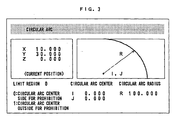
- FIG. 3 is a view of a display screen for specifying a zone by a circular arc in accordance with the embodiment of the present invention.
- a zone is specified based on a basic figure such as a circle, a straight line, or a circular arc.
- a circle is defined by inputting, for example, the coordinates of the center and radius of the circle, and then the range is specified by specifying the inside or outside of the circle.
- a straight line is defined by inputting, for example, the coordinates of two points or the coordinates of one point and the angle of a line segment, and the zone is specified by specifying upper or lower side or right or left side of the straight line.
- a circular arc is defined by inputting, for example, the coordinates of the center and radius of circular arc, and a zone is specified by specifying the same side as or the opposite side to the center of the circular arc.
- zones can be specified by combining basic figures such as those of the aforementioned zone specification by a circle, zone specification by a straight line, or zone specification by a circular arc.
- a triangular zone can be specified by combining the zones by three straight lines.
- the zone is specified on a display screen such as a CRT.
- FIGS. 1 to 3 show one embodiment of the display screen for specification.
- the data on each display is divided into a section for displaying the specified shape, a section for displaying the current position of the moving part to be controlled, a section for displaying the specified figure, a section for displaying the data defining the specified figure, and a section for determining the zone to be specified either as the moving zone or prohibited zone of the moving part to be controlled.
- the current position is displayed by the position data from a non illustrated control unit.
- Other sections are for display in accordance with the input value from a non illustrated input device.
- zone specification by a basic figure in accordance with the embodiment of the present invention including zone specification by a circle, zone specification by a straight line, and zone specification by a circular arc, will be described below with reference to FIGS. 1 to 3.
- FIG. 1 shows a display screen for specifying a zone by a circle on a display screen such as a CRT used for the zone specification in the embodiment of the present invention.
- the currently specified shape of zone is a circle is indicated, for example, in the form of the title display; the current position of the moving part to be controlled as the coordinate data of X, Y and Z axes; the currently specified shape by a figure shape of a circle; the coordinate data of the center of circle by the values of I and J; and the radius of circle by the value of R.
- the inside of the circle is the prohibition zone is indicated by the selection of the movement zone and the prohibition zone in the limit region.
- the values of coordinate data I and J of the center of circle and the value of radius R of the circle are inputted, and the figure can be displayed on the screen by the internal processing in accordance with these values.
- the specification of the figure shape can be made by setting the tool diameter ⁇ and considering the set tool diameter ⁇ .
- FIG. 2 shows a display screen for specifying a zone by a straight line on a screen such as a CRT used for the zone specification in the embodiment of the present invention.
- the currently specified shape of zone is a straight line is indicated by the title display;
- the current position of the moving part to be controlled is, like the zone specification by a circle, indicated by the coordinate data of X, Y and Z axes;
- the currently specified shape by a figure shape of straight line;
- This straight line is set as a line segment defined by aforesaid two points or one point and an angle and extends toward both directions.
- the value ⁇ sets the tool diameter.
- the limit region is specified by the upper or lower side of the straight line when viewed facing the front of the screen.
- the limit region can also be specified by the right or left side of the straight line when viewed facing the front of the screen.
- the coordinate data X1, Y1 and X2, Y2 of the start point and the end point of the straight line or the coordinate data X1, Y1 of the start point of the straight line and the angle A indicating the direction of the straight line are inputted, and the figure can be displayed on the screen by the internal processing in accordance with these values.
- FIG. 3 shows a display screen for specifying a zone by a circular arc on a display screen such as a CRT used for the zone specification in the embodiment of the present invention.
- the currently specified shape of zone is a circular arc is indicated by the title display;
- the current position of the moving part to be controlled is, like the zone specification by a circle or a straight line, indicated by the coordinate data of X, Y and Z axes;
- the currently specified shape by a figure shape of circular arc; the coordinate data of the center of circular arc by the values of I and J; and the radius of circular arc by the value of R.
- the side on which the center of circular arc lies is the prohibition zone is indicated by the selection of the movement zone and the prohibition zone in the limit region.
- the values of coordinate data I and J of the center of circular arc and the value of radius R of the circular arc are inputted, and the figure can be displayed on the screen by the internal processing in accordance with these values.
- the specification of the figure shape can also be made by setting the tool diameter ⁇ and by considering the tool diameter ⁇ . If the center of circular arc cannot be displayed on the screen, a virtual center can be displayed.
- the limit region of the movement zone or the prohibition zone of the moving part to be controlled can be distinguished by any display technique such as color, pattern, or flash display on the screen.
- a processor 11 controls the entire of the numerical control unit in accordance with a system program stored in ROM 12.
- the software to be executed by the system program of this ROM 12 has functions such as figure storage, interpolation, etc.
- EPROM or EEPROM is used for the ROM 12.
- a nonvolatile memory 14 uses CMOS backed up by a not non illustrated battery. The nonvolatile memory 14 stores various data such as parameters which should be kept even after power shutoff, and machining program.
- a graphics control circuit 15 converts the guidance information, inputted specified shape, etc. into a signal which can be displayed, and gives the signal to a display 16.
- the display 16 uses a CRT or a liquid crystal display device.
- An axis control circuit 18 (for three axes), receiving the movement command of axis including the interpolation pulse CP from the processor 11, outputs the movement command of this axis to a servo amplifier 19 (for three axes).
- the servo amplifier 19 receiving this movement command, drives a non illustrated servomotor of a machine tool 20.
- the machine tool 20 has a machine control panel 40 to be used in executing the movement command in addition to driving the servomotor.
- a PMC (Programmable Machine Controller) 22 receives T function signal (tool selection command) etc. via the bus 30 during the execution of the machining program. This signal is processed by a sequence program, and is outputted as the operation command to control the machine tool 20. Also, the PMC receives a state signal from the machine tool 20, performs sequence processing, and transmits an input signal necessary for the processor 11 via the bus 30.
- the software key 23 is provided in a CRT/MDI unit 25 together with the display 16 and a keyboard 17.
- FIGS. 5 and 6 show a case in which a zone is specified by combining straight line zones.
- FIG. 5 shows zone displayed on a screen
- FIG. 6 shows the conditions for zone specification.
- a zone is specified by three straight lines L1, L2, and L3.
- the zone is divided into seven zones P1 to P7 by these three straight lines.
- zone P1 is set as a zone lying on the upper sides of all the straight lines L1, L2, and L3.
- the values of Y coordinate of straight lines L1, L2 and L3 corresponding to the x coordinate are Y1, Y2 and Y3, respectively.
- the condition that point (x, y) lies in zone P1 holds when all inequalities of y > Y1 for straight line L1, y > Y2 for straight line L2, and y > Y3 for straight line L3 are satisfied, as shown in FIG. 6.
- zone specification can be performed by the conditions shown in FIG. 6.
- Y coordinate of the straight lines L1, L2 and L3 corresponding to x coordinate can be determined, for example, by substituting x coordinate into the expression representing respective straight lines L1, L2 and L3.
- the calculation by the conditional inequality in this zone specification can be performed in the processor 11.
- FIGS. 7 and 8 show a case in which a zone is specified by combining straight line zone and circle zone.
- FIG. 7 shows zones displayed on a screen
- FIG. 8 shows the conditions for zone specification.
- a zone is specified by one straight line L and one circle C with radius R.
- the zone is divided into four zones P11 to P14 by one straight line and one circle.
- zone P11 is set as the zone lying on the lower side of straight line L and on the outside of circle C
- zone P12 is set as the zone lying on the lower side of straight line L and on the inside of circle C.
- the values of Y coordinate of straight lines L corresponding to x coordinate is Y.
- the condition that point (x, y) lies in zone P12 is to satisfy both the inequalities of y ⁇ Y for straight line L and d ⁇ R for circle C, as shown in FIG. 8.
- zones P11, P13 and P14 can be specified by the condition of inequality for straight line L and the condition of inequity for circle C as shown in FIG. 8.
- conditional expression for zone specification differs depending on the defining expressions of straight line and circle.
- zone specification it is not necessary to set conditions for zone specification as shown in FIG. 8 for all zones P11 to P14 formed by being divided by straight line L and circle C.
- the condition is inputted only for the zone to be specified so that only the necessary zone can be specified.
- the movement control for the moving part to be controlled will be described below with reference to FIGS. 9 to 16, by using the zone such as the movement zone and the prohibition zone specified by the above-described zone specification method of the present invention.
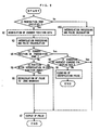
- FIG. 9 is a flowchart illustrating the movement control of the moving part being controlled in the specified zone of the embodiment of the present invention.
- FIGS. 10, 11 and 12 are flowcharts for determining whether the movement command is for in the direction in which the moving part being controlled is allowed to get out of the prohibition zone to the movement zone.
- FIGS. 13 to 16 are diagrams for illustrating the process for determining whether the movement command is for the direction in which the moving part to be controlled is allowed to get out of the prohibition zone to the movement zone.
- Step S1 First, it is determined whether the prohibition zone, in which the movement of the moving part to be controlled is prohibited in the zone specification, is specified.
- the data of the specified zone is stored in the nonvolatile memory 14.
- the processor 11 calls the nonvolatile memory 14, and determines whether the prohibition zone is present.
- Step S2 If the result of judgment in Step S1 indicates that prohibition zone is specified, the processor 11 detects the current position of the moving part to be controlled to acquire the position data, and stores it in the memory such as the RAM 13.
- Step S3 The processor 11 calls the nonvolatile memory 14 to determine the target position data of the moving part to be controlled, executes interpolation processing of the numerical control unit between the current position acquired in Step S2 and the target position of the moving part to be controlled, executes pulse calculation for driving the pulse motor, and stores the result in the memory such as the RAM 13.
- Step S4 Next, the processor 11 calls the position data for the current position stored in the memory such as the RAM 13, and determines whether the current position of the moving part to be controlled is in the prohibition zone, from the data of prohibition zone stored in the memory such as the nonvolatile memory 14. This determination can be made by applying the current position data of the moving part to be controlled to the conditional expression such as an inequality which specifies the prohibition zone.
- Step S5 As a result of the determination in Step S4, if the current position of the moving part to be controlled is in the movement zone, not in the prohibition zone, the processor 11 reads the target position data of the moving part to be controlled, which is stored in the memory such as the RAM 13, and determines whether the position of the moving part to be controlled after interpolation is in the prohibition zone. This determination can be made by applying the position data of the moving part to be controlled after interpolation to the conditional expression such as an inequality which specifies the prohibition zone.
- Step S6 As a result of the determination in Step S5, if the position of the moving part to be controlled after interpolation is in the prohibition zone, the pulse to the zone boundary on the line connecting the current position and the position after interpolation is calculated. By this pulse calculation, a pulse signal can be acquired, which causes the moving part to be controlled to be moved up to the point immediately before the boundary of the movement zone and the prohibition zone.
- Step S7 The interpolation pulse determined in the process of Step S6 is outputted. This pulse output allows the moving part to be controlled to be moved up to the point immediately before the boundary of a zone and the prohibition zone.
- Step S10, S7 If the result of judgment in Step S1 indicates that the prohibition zone, in which the movement of the moving part being controlled is prohibited, is not specified, since there is no limit to the movement zone of the moving part to be controlled, pulse calculation for movement is executed after interpolation processing, and the interpolation pulse is outputted in Step S7. By this output of interpolation pulse, the moving part to be controlled moves to the intended end position of movement.
- Step S8 If the result of judgment in Step S4 indicates that current position of the moving part to be controlled is in the prohibition zone, when the moving part to be controlled is moved in the direction commanded by the movement command at that time, it is determined whether or not the moving part to be controlled enters the movement zone from the prohibition zone. For this purpose, it is determined whether the direction commanded by the movement command is the direction in which the moving part to be controlled is allowed to get out of the prohibition zone.
- Step S7 pulse is outputted in Step S7 by using the pulse calculated in the process of Step S3, by which the movement is executed.
- Step S9 If the result of judgment in Step S8 indicates that direction commanded by the movement command is not the direction in which the moving part to be controlled is allowed to get out of the prohibition zone, the interpolation pulse calculated in the process of Step S3 is cleared to complete the processing.
- Step S8 the direction commanded by the movement command in Step S8 is checked, and it is determined whether the movement direction is the direction in which the moving part to be controlled moves from the prohibition zone to the movement zone.
- One embodiment of the flow of processing applied in the case where the zone is specified by a circle, one embodiment of the flow of processing applied in the case where the zone is specified by a straight line, and one embodiment of the flow of processing applied in the case where the zone is specified by a circle, straight line, and a circular arc will be described below.
- the zone is specified by straight lines
- the upper side of a straight line 110 is specified as the prohibition zone.
- This straight line 110 can be stored in, for example, the nonvolatile memory 14, and can be called by the processor 11.
- the center of a tool 111 lies at position Q1, and the center of a tool 113 lies at position Q3.
- the tool 113 moves along the direction 113a or 113b and in the normal direction with respect to the straight line 110.
- a function for stopping output of the interpolation pulse by the input of a predetermined coordinate value can be added.
- FIG. 18 on the X-Y coordinate axis plane, the upper side of a circular arc 120 is specified as the prohibition zone.
- This circular arc 120 can be stored in, for example, the nonvolatile memory 14, and called by the processor 11.
- the center of a tool 121 lies at position Q5, and the center of a tool 122 lies at position Q6.
- parallel movement is selected by the machine control panel 40 of the machine tool 20, and jog feed or handle feed by the manual pulse generator 41 is performed.
- the tool 121 moves in the direction 121a or 121b while keeping a fixed distance from the circular arc 120.
- the fixed distance at this time is a normal component between the tool position 121 and the circular arc 120.
- the tool 122 moves along the direction 122a or 122b and in the normal direction with respect to the circular arc 120.
- the machining zone can easily be set by basic figures defined by a straight line, a circle, or a circular arc.
- the zone specifications such as the movement zone specification or the prohibition zone specification for the moving part to be controlled are made by the zone specification by a circle, zone specification by a straight line, or the zone specification by a circular arc, or by the combination of these methods.
- the polygonal zone is set in advance so that the zone specification can also be made by using the polygonal zone.
- the specification of the movement zone or the prohibition zone of the moving part to be controlled can easily be made without strictly defining as numerical data the position information about the aftermove position or the movement limit of the moving part to be controlled.
Landscapes
- Engineering & Computer Science (AREA)
- Physics & Mathematics (AREA)
- Human Computer Interaction (AREA)
- Manufacturing & Machinery (AREA)
- General Physics & Mathematics (AREA)
- Automation & Control Theory (AREA)
- Geometry (AREA)
- Numerical Control (AREA)
Claims (3)
- Verfahren zum Festlegen eines Bewegungsbereichs, innerhalb dessen eine Bewegung eines numerisch gesteuerten bewegbaren Maschinenteils zugelassen ist, das Schritte umfasst zumwelches Verfahren gekennzeichnet ist durch Schritte zumEingeben von Daten, die eine Grenzlinie angeben, die eine Grenzform eines Bewegungsbereichs bildet, undEingeben von Daten, die angeben, welche von zwei Ebenen, die durch die Grenzlinie unterteilt sind, den Bewegungsbereich enthält, um dadurch den Bewegungsbereich zu bestimmen,Beurteilen, ob eine gegenwärtige Position eines bewegbaren Maschinenteils innerhalb des bestimmten Bewegungsbereichs liegt oder nicht,Beurteilen, ob eine interpolierte Position des bewegbaren Maschinenteils innerhalb des bestimmten Bewegungsbereichs liegt oder nicht, wobei sich die interpolierte Position aus einer Verarbeitung zur Interpolation zwischen der gegenwärtigen Position des bewegbaren Maschinenteils und einer Zielposition desselben ergibt,Ausführen der Bewegung des bewegbaren Maschinenteils zu der interpolierten Position, wenn sowohl die gegenwärtige Position als auch die interpolierte Position des bewegbaren Maschinenteils innerhalb des bestimmten Bewegungsbereichs liegt, undAusführen der Bewegung des bewegbaren Maschinenteils zu der Grenzlinien,wenn die gegenwärtige Position innerhalb des Bewegungsbereichs liegt, die interpolierte Position jedoch nicht innerhalb des Bewegungsbereichs liegt.
- Verfahren zum Festlegen eines Bewegungsbereichs nach Anspruch 1, das ferner einen Schritt umfasst zum Ausführen einer Bewegung des bewegbaren Maschinenteils, wenn die gegenwärtige Position nicht innerhalb des Bewegungsbereichs liegt, die interpolierte Position jedoch innerhalb des Bewegungsbereichs liegt.
- Verfahren zum Festlegen eines Bewegungsbereichs nach Anspruch 1 oder 2, wobei die Grenzlinie aus einer Garden und/ oder einem Kreis und/oder einem Kreisbogen besteht.
Applications Claiming Priority (4)
| Application Number | Priority Date | Filing Date | Title |
|---|---|---|---|
| JP16506593 | 1993-06-11 | ||
| JP16506593A JP3574462B2 (ja) | 1993-06-11 | 1993-06-11 | 領域指定方法 |
| JP165065/93 | 1993-06-11 | ||
| PCT/JP1994/000931 WO1994029777A1 (en) | 1993-06-11 | 1994-06-08 | Region designating method |
Publications (3)
| Publication Number | Publication Date |
|---|---|
| EP0664498A1 EP0664498A1 (de) | 1995-07-26 |
| EP0664498A4 EP0664498A4 (de) | 1997-07-16 |
| EP0664498B1 true EP0664498B1 (de) | 2001-08-22 |
Family
ID=15805202
Family Applications (1)
| Application Number | Title | Priority Date | Filing Date |
|---|---|---|---|
| EP94917787A Expired - Lifetime EP0664498B1 (de) | 1993-06-11 | 1994-06-08 | Verfahren zur bezeichnung eines gebietes |
Country Status (6)
| Country | Link |
|---|---|
| US (1) | US5611032A (de) |
| EP (1) | EP0664498B1 (de) |
| JP (1) | JP3574462B2 (de) |
| KR (1) | KR0149710B1 (de) |
| DE (1) | DE69428031T2 (de) |
| WO (1) | WO1994029777A1 (de) |
Families Citing this family (10)
| Publication number | Priority date | Publication date | Assignee | Title |
|---|---|---|---|---|
| US6768563B1 (en) | 1995-02-24 | 2004-07-27 | Canon Kabushiki Kaisha | Image input system |
| DE19600538A1 (de) * | 1996-01-09 | 1997-07-10 | Agie Ag Ind Elektronik | Verfahren und Vorrichtung zur Steuerung einer Funkenerosionsmaschine |
| JPH1094945A (ja) | 1996-09-19 | 1998-04-14 | Fanuc Ltd | 数値制御装置における加工リミット領域指定方法および手動加工方法 |
| JP4891528B2 (ja) * | 2004-04-07 | 2012-03-07 | オークマ株式会社 | 加工時間算出装置 |
| WO2008149431A1 (ja) * | 2007-06-06 | 2008-12-11 | Mitsubishi Electric Corporation | プログラム作成装置、数値制御装置およびプログラム作成方法 |
| JP2009028872A (ja) * | 2007-07-30 | 2009-02-12 | Star Micronics Co Ltd | 工作機械の移動制御装置 |
| US9459616B2 (en) * | 2007-08-03 | 2016-10-04 | Hurco Companies, Inc. | Universal conversational programming for machine tool systems |
| US8844104B2 (en) * | 2009-04-22 | 2014-09-30 | Hurco Companies, Inc. | Multi-zone machine tool system |
| JP5199425B2 (ja) * | 2011-08-17 | 2013-05-15 | ファナック株式会社 | 自動的に加工方向を切換え可能な手動加工機能を備えた数値制御装置 |
| JP6363567B2 (ja) * | 2015-08-10 | 2018-07-25 | ファナック株式会社 | ストロークリミット近傍のテスト運転で移動量を制限する数値制御装置 |
Family Cites Families (19)
| Publication number | Priority date | Publication date | Assignee | Title |
|---|---|---|---|---|
| JPS6044293A (ja) | 1983-08-18 | 1985-03-09 | 株式会社日立製作所 | 産業用ロボットの制御装置 |
| JPS60189507A (ja) * | 1984-03-11 | 1985-09-27 | Mitsubishi Electric Corp | 産業機械の制御装置 |
| JPS60191365A (ja) * | 1984-03-13 | 1985-09-28 | Okuma Mach Works Ltd | 自動プログラミング機能における形状入力方式 |
| JPS60230205A (ja) * | 1984-04-27 | 1985-11-15 | Fanuc Ltd | 数値制御方式 |
| JPS6273385A (ja) * | 1985-09-27 | 1987-04-04 | Toshiba Corp | 境界検出対象領域指示回路 |
| JPS63236106A (ja) * | 1987-03-24 | 1988-10-03 | Fanuc Ltd | 工具通路制御方式 |
| JPH0729255B2 (ja) * | 1987-09-10 | 1995-04-05 | ファナック株式会社 | 旋削加工用のncデータ作成方式 |
| JPH01102605A (ja) * | 1987-10-15 | 1989-04-20 | Fanuc Ltd | 輪郭形状修正方法 |
| JPH0698552B2 (ja) * | 1988-12-26 | 1994-12-07 | オ−クマ株式会社 | 数値制御情報作成装置における加工方法の決定方式 |
| JPH0760336B2 (ja) * | 1988-12-28 | 1995-06-28 | オ−クマ株式会社 | 数値制御装置 |
| JPH02311296A (ja) * | 1989-05-23 | 1990-12-26 | Daikin Ind Ltd | 産業用ロボット制御方法およびその装置 |
| AU7186491A (en) * | 1990-01-30 | 1991-08-21 | Omron Corporation | Image processor |
| JP2821245B2 (ja) * | 1990-06-27 | 1998-11-05 | 豊田工機株式会社 | 加工領域指定装置 |
| JPH04164562A (ja) * | 1990-10-24 | 1992-06-10 | Osaka Kiko Co Ltd | 研磨加工における領域設定方法及び装置 |
| JPH04269152A (ja) * | 1991-02-21 | 1992-09-25 | Toshiba Mach Co Ltd | 数値制御工作機械における内円切削制御装置 |
| JPH0511828A (ja) * | 1991-07-05 | 1993-01-22 | Fanuc Ltd | フイレツト曲面創成位置の指定方法 |
| JPH05265532A (ja) * | 1992-03-24 | 1993-10-15 | Okuma Mach Works Ltd | 数値制御装置におけるリミットデータ設定方法 |
| JP3263146B2 (ja) * | 1992-10-12 | 2002-03-04 | ファナック株式会社 | 数値制御装置 |
| US5411272A (en) * | 1992-11-20 | 1995-05-02 | Sega Of America, Inc. | Video game with spiral loop graphics |
-
1993
- 1993-06-11 JP JP16506593A patent/JP3574462B2/ja not_active Expired - Fee Related
-
1994
- 1994-06-08 US US08/379,657 patent/US5611032A/en not_active Expired - Lifetime
- 1994-06-08 KR KR1019940704784A patent/KR0149710B1/ko not_active Expired - Fee Related
- 1994-06-08 WO PCT/JP1994/000931 patent/WO1994029777A1/ja not_active Ceased
- 1994-06-08 EP EP94917787A patent/EP0664498B1/de not_active Expired - Lifetime
- 1994-06-08 DE DE69428031T patent/DE69428031T2/de not_active Expired - Fee Related
Also Published As
| Publication number | Publication date |
|---|---|
| US5611032A (en) | 1997-03-11 |
| EP0664498A4 (de) | 1997-07-16 |
| WO1994029777A1 (en) | 1994-12-22 |
| EP0664498A1 (de) | 1995-07-26 |
| DE69428031T2 (de) | 2002-01-03 |
| JP3574462B2 (ja) | 2004-10-06 |
| DE69428031D1 (de) | 2001-09-27 |
| KR950702143A (ko) | 1995-06-19 |
| KR0149710B1 (ko) | 1998-12-15 |
| JPH06348327A (ja) | 1994-12-22 |
Similar Documents
| Publication | Publication Date | Title |
|---|---|---|
| EP0530790B1 (de) | Werkzeugvorschubsteuerung einer numerisch gesteuerten Einheit | |
| EP0664498B1 (de) | Verfahren zur bezeichnung eines gebietes | |
| KR0133198B1 (ko) | 수치 제어 장치 | |
| JP2002172543A (ja) | 加工装置の制御パラメータ設定装置及び制御パラメータ設定方法 | |
| EP0063615B1 (de) | Numerische steuerverfahren | |
| EP0780745B1 (de) | Verfahren und vorrichtung zur freien kurveninterpolation | |
| US5099432A (en) | Method for determining machining process in numerical control information generating function | |
| EP0357785B1 (de) | Verfahren zur erzeugung einer werkzeugoffset bahn | |
| US5920170A (en) | Numerical control apparatus and numerical control method | |
| KR0145347B1 (ko) | 수치 제어 장치 및 수치 제어 방법 | |
| US5347461A (en) | Tool travel path creating method | |
| KR20040038477A (ko) | 공작물 기계 원점 좌표 설정 시스템 및 방법 | |
| JP3040263B2 (ja) | 数値制御装置及び数値制御方法 | |
| JP3075861B2 (ja) | 数値制御装置 | |
| JPS63196906A (ja) | 旋盤用プログラミング装置 | |
| JP3263146B2 (ja) | 数値制御装置 | |
| EP0371142B1 (de) | Korrekturverfahren für geometrische stellen bei industriellen robotern | |
| JP3471644B2 (ja) | 領域加工運転用の制御装置 | |
| JP3045603B2 (ja) | 数値制御装置 | |
| JPH0957598A (ja) | 数値制御装置と、その加工軌跡制御方式 | |
| JPH06222821A (ja) | 数値制御装置 | |
| KR0155014B1 (ko) | 수치 제어 장치 | |
| KR940007085B1 (ko) | 와이어 커트 방전 가공기의 코너 가공 방법 | |
| Kittel et al. | Introduction of a CAM feature model for laser beam welding | |
| KR0168070B1 (ko) | 공구직경에 따른 이동경로 보정방법 |
Legal Events
| Date | Code | Title | Description |
|---|---|---|---|
| PUAI | Public reference made under article 153(3) epc to a published international application that has entered the european phase |
Free format text: ORIGINAL CODE: 0009012 |
|
| 17P | Request for examination filed |
Effective date: 19950306 |
|
| AK | Designated contracting states |
Kind code of ref document: A1 Designated state(s): CH DE IT LI |
|
| A4 | Supplementary search report drawn up and despatched | ||
| AK | Designated contracting states |
Kind code of ref document: A4 Designated state(s): CH DE IT LI |
|
| 17Q | First examination report despatched |
Effective date: 19990318 |
|
| GRAG | Despatch of communication of intention to grant |
Free format text: ORIGINAL CODE: EPIDOS AGRA |
|
| GRAG | Despatch of communication of intention to grant |
Free format text: ORIGINAL CODE: EPIDOS AGRA |
|
| GRAH | Despatch of communication of intention to grant a patent |
Free format text: ORIGINAL CODE: EPIDOS IGRA |
|
| GRAH | Despatch of communication of intention to grant a patent |
Free format text: ORIGINAL CODE: EPIDOS IGRA |
|
| GRAA | (expected) grant |
Free format text: ORIGINAL CODE: 0009210 |
|
| AK | Designated contracting states |
Kind code of ref document: B1 Designated state(s): CH DE IT LI |
|
| PG25 | Lapsed in a contracting state [announced via postgrant information from national office to epo] |
Ref country code: LI Free format text: LAPSE BECAUSE OF FAILURE TO SUBMIT A TRANSLATION OF THE DESCRIPTION OR TO PAY THE FEE WITHIN THE PRESCRIBED TIME-LIMIT Effective date: 20010822 Ref country code: IT Free format text: LAPSE BECAUSE OF FAILURE TO SUBMIT A TRANSLATION OF THE DESCRIPTION OR TO PAY THE FEE WITHIN THE PRE;WARNING: LAPSES OF ITALIAN PATENTS WITH EFFECTIVE DATE BEFORE 2007 MAY HAVE OCCURRED AT ANY TIME BEFORE 2007. THE CORRECT EFFECTIVE DATE MAY BE DIFFERENT FROM THE ONE RECORDED.SCRIBED TIME-LIMIT Effective date: 20010822 Ref country code: CH Free format text: LAPSE BECAUSE OF FAILURE TO SUBMIT A TRANSLATION OF THE DESCRIPTION OR TO PAY THE FEE WITHIN THE PRESCRIBED TIME-LIMIT Effective date: 20010822 |
|
| RIC1 | Information provided on ipc code assigned before grant |
Free format text: 7G 05B 19/406 A |
|
| REG | Reference to a national code |
Ref country code: CH Ref legal event code: EP |
|
| REF | Corresponds to: |
Ref document number: 69428031 Country of ref document: DE Date of ref document: 20010927 |
|
| REG | Reference to a national code |
Ref country code: CH Ref legal event code: PL |
|
| PLBE | No opposition filed within time limit |
Free format text: ORIGINAL CODE: 0009261 |
|
| STAA | Information on the status of an ep patent application or granted ep patent |
Free format text: STATUS: NO OPPOSITION FILED WITHIN TIME LIMIT |
|
| 26N | No opposition filed | ||
| PGFP | Annual fee paid to national office [announced via postgrant information from national office to epo] |
Ref country code: DE Payment date: 20090604 Year of fee payment: 16 |
|
| PG25 | Lapsed in a contracting state [announced via postgrant information from national office to epo] |
Ref country code: DE Free format text: LAPSE BECAUSE OF NON-PAYMENT OF DUE FEES Effective date: 20110101 |