EP0664919B1 - Support d'enregistrement et appareil pour produire des sons et/ou des images - Google Patents
Support d'enregistrement et appareil pour produire des sons et/ou des images Download PDFInfo
- Publication number
- EP0664919B1 EP0664919B1 EP93923479A EP93923479A EP0664919B1 EP 0664919 B1 EP0664919 B1 EP 0664919B1 EP 93923479 A EP93923479 A EP 93923479A EP 93923479 A EP93923479 A EP 93923479A EP 0664919 B1 EP0664919 B1 EP 0664919B1
- Authority
- EP
- European Patent Office
- Prior art keywords
- control signal
- generator
- sound
- appliance according
- control
- Prior art date
- Legal status (The legal status is an assumption and is not a legal conclusion. Google has not performed a legal analysis and makes no representation as to the accuracy of the status listed.)
- Expired - Lifetime
Links
- 239000003205 fragrance Substances 0.000 claims description 99
- 230000005236 sound signal Effects 0.000 claims description 25
- 239000003094 microcapsule Substances 0.000 claims description 22
- 230000008878 coupling Effects 0.000 claims description 10
- 238000010168 coupling process Methods 0.000 claims description 10
- 238000005859 coupling reaction Methods 0.000 claims description 10
- 239000007788 liquid Substances 0.000 claims description 8
- 239000000758 substrate Substances 0.000 claims description 7
- 239000002775 capsule Substances 0.000 claims description 6
- QVGXLLKOCUKJST-UHFFFAOYSA-N atomic oxygen Chemical compound [O] QVGXLLKOCUKJST-UHFFFAOYSA-N 0.000 claims description 5
- 239000000463 material Substances 0.000 claims description 5
- 239000001301 oxygen Substances 0.000 claims description 5
- 229910052760 oxygen Inorganic materials 0.000 claims description 5
- 239000007921 spray Substances 0.000 claims description 5
- 239000012159 carrier gas Substances 0.000 claims description 4
- 230000006870 function Effects 0.000 claims description 4
- 239000000203 mixture Substances 0.000 claims description 4
- 230000033764 rhythmic process Effects 0.000 claims description 4
- 238000007598 dipping method Methods 0.000 claims 1
- 238000011161 development Methods 0.000 description 9
- 230000018109 developmental process Effects 0.000 description 9
- 238000010586 diagram Methods 0.000 description 9
- 230000033458 reproduction Effects 0.000 description 9
- 230000000007 visual effect Effects 0.000 description 8
- 230000004048 modification Effects 0.000 description 6
- 238000012986 modification Methods 0.000 description 6
- 230000003287 optical effect Effects 0.000 description 5
- 230000008520 organization Effects 0.000 description 5
- 239000003086 colorant Substances 0.000 description 4
- 238000013270 controlled release Methods 0.000 description 4
- 210000000056 organ Anatomy 0.000 description 4
- 230000002040 relaxant effect Effects 0.000 description 4
- 230000001953 sensory effect Effects 0.000 description 4
- 238000002604 ultrasonography Methods 0.000 description 4
- 108010076504 Protein Sorting Signals Proteins 0.000 description 3
- 230000008901 benefit Effects 0.000 description 3
- 230000001914 calming effect Effects 0.000 description 3
- 230000008859 change Effects 0.000 description 3
- 239000011521 glass Substances 0.000 description 3
- 230000004936 stimulating effect Effects 0.000 description 3
- 230000004913 activation Effects 0.000 description 2
- 230000005587 bubbling Effects 0.000 description 2
- 230000000694 effects Effects 0.000 description 2
- 230000033001 locomotion Effects 0.000 description 2
- 238000010606 normalization Methods 0.000 description 2
- 238000000926 separation method Methods 0.000 description 2
- 238000001228 spectrum Methods 0.000 description 2
- 230000002123 temporal effect Effects 0.000 description 2
- 108010010803 Gelatin Proteins 0.000 description 1
- 238000010521 absorption reaction Methods 0.000 description 1
- 230000003213 activating effect Effects 0.000 description 1
- 230000005540 biological transmission Effects 0.000 description 1
- 230000000903 blocking effect Effects 0.000 description 1
- 239000000969 carrier Substances 0.000 description 1
- 238000001444 catalytic combustion detection Methods 0.000 description 1
- 210000005069 ears Anatomy 0.000 description 1
- 238000001914 filtration Methods 0.000 description 1
- 239000000796 flavoring agent Substances 0.000 description 1
- 235000019634 flavors Nutrition 0.000 description 1
- 229920000159 gelatin Polymers 0.000 description 1
- 239000008273 gelatin Substances 0.000 description 1
- 235000019322 gelatine Nutrition 0.000 description 1
- 235000011852 gelatine desserts Nutrition 0.000 description 1
- 238000010438 heat treatment Methods 0.000 description 1
- 238000005470 impregnation Methods 0.000 description 1
- 230000006872 improvement Effects 0.000 description 1
- 230000002452 interceptive effect Effects 0.000 description 1
- 238000004519 manufacturing process Methods 0.000 description 1
- 239000012528 membrane Substances 0.000 description 1
- 238000001208 nuclear magnetic resonance pulse sequence Methods 0.000 description 1
- 230000000717 retained effect Effects 0.000 description 1
- 230000001020 rhythmical effect Effects 0.000 description 1
- 238000007493 shaping process Methods 0.000 description 1
- 230000008054 signal transmission Effects 0.000 description 1
- 238000004088 simulation Methods 0.000 description 1
- 230000000638 stimulation Effects 0.000 description 1
- 230000001360 synchronised effect Effects 0.000 description 1
- 230000009466 transformation Effects 0.000 description 1
- 238000004804 winding Methods 0.000 description 1
Images



Classifications
-
- H—ELECTRICITY
- H04—ELECTRIC COMMUNICATION TECHNIQUE
- H04N—PICTORIAL COMMUNICATION, e.g. TELEVISION
- H04N5/00—Details of television systems
- H04N5/76—Television signal recording
- H04N5/84—Television signal recording using optical recording
- H04N5/85—Television signal recording using optical recording on discs or drums
-
- A—HUMAN NECESSITIES
- A61—MEDICAL OR VETERINARY SCIENCE; HYGIENE
- A61L—METHODS OR APPARATUS FOR STERILISING MATERIALS OR OBJECTS IN GENERAL; DISINFECTION, STERILISATION OR DEODORISATION OF AIR; CHEMICAL ASPECTS OF BANDAGES, DRESSINGS, ABSORBENT PADS OR SURGICAL ARTICLES; MATERIALS FOR BANDAGES, DRESSINGS, ABSORBENT PADS OR SURGICAL ARTICLES
- A61L9/00—Disinfection, sterilisation or deodorisation of air
- A61L9/015—Disinfection, sterilisation or deodorisation of air using gaseous or vaporous substances, e.g. ozone
- A61L9/04—Disinfection, sterilisation or deodorisation of air using gaseous or vaporous substances, e.g. ozone using substances evaporated in the air without heating
- A61L9/12—Apparatus, e.g. holders, therefor
- A61L9/125—Apparatus, e.g. holders, therefor emanating multiple odours
-
- A—HUMAN NECESSITIES
- A61—MEDICAL OR VETERINARY SCIENCE; HYGIENE
- A61M—DEVICES FOR INTRODUCING MEDIA INTO, OR ONTO, THE BODY; DEVICES FOR TRANSDUCING BODY MEDIA OR FOR TAKING MEDIA FROM THE BODY; DEVICES FOR PRODUCING OR ENDING SLEEP OR STUPOR
- A61M15/00—Inhalators
- A61M15/0001—Details of inhalators; Constructional features thereof
- A61M15/0003—Details of inhalators; Constructional features thereof with means for dispensing more than one drug
-
- A—HUMAN NECESSITIES
- A61—MEDICAL OR VETERINARY SCIENCE; HYGIENE
- A61M—DEVICES FOR INTRODUCING MEDIA INTO, OR ONTO, THE BODY; DEVICES FOR TRANSDUCING BODY MEDIA OR FOR TAKING MEDIA FROM THE BODY; DEVICES FOR PRODUCING OR ENDING SLEEP OR STUPOR
- A61M15/00—Inhalators
- A61M15/0028—Inhalators using prepacked dosages, one for each application, e.g. capsules to be perforated or broken-up
- A61M15/003—Inhalators using prepacked dosages, one for each application, e.g. capsules to be perforated or broken-up using capsules, e.g. to be perforated or broken-up
- A61M15/0031—Inhalators using prepacked dosages, one for each application, e.g. capsules to be perforated or broken-up using capsules, e.g. to be perforated or broken-up by bursting or breaking the package, i.e. without cutting or piercing
-
- A—HUMAN NECESSITIES
- A61—MEDICAL OR VETERINARY SCIENCE; HYGIENE
- A61M—DEVICES FOR INTRODUCING MEDIA INTO, OR ONTO, THE BODY; DEVICES FOR TRANSDUCING BODY MEDIA OR FOR TAKING MEDIA FROM THE BODY; DEVICES FOR PRODUCING OR ENDING SLEEP OR STUPOR
- A61M15/00—Inhalators
- A61M15/0028—Inhalators using prepacked dosages, one for each application, e.g. capsules to be perforated or broken-up
- A61M15/0045—Inhalators using prepacked dosages, one for each application, e.g. capsules to be perforated or broken-up using multiple prepacked dosages on a same carrier, e.g. blisters
- A61M15/0046—Inhalators using prepacked dosages, one for each application, e.g. capsules to be perforated or broken-up using multiple prepacked dosages on a same carrier, e.g. blisters characterized by the type of carrier
- A61M15/0051—Inhalators using prepacked dosages, one for each application, e.g. capsules to be perforated or broken-up using multiple prepacked dosages on a same carrier, e.g. blisters characterized by the type of carrier the dosages being arranged on a tape, e.g. strips
-
- A—HUMAN NECESSITIES
- A63—SPORTS; GAMES; AMUSEMENTS
- A63J—DEVICES FOR THEATRES, CIRCUSES, OR THE LIKE; CONJURING APPLIANCES OR THE LIKE
- A63J17/00—Apparatus for performing colour-music
-
- A—HUMAN NECESSITIES
- A63—SPORTS; GAMES; AMUSEMENTS
- A63J—DEVICES FOR THEATRES, CIRCUSES, OR THE LIKE; CONJURING APPLIANCES OR THE LIKE
- A63J5/00—Auxiliaries for producing special effects on stages, or in circuses or arenas
-
- G—PHYSICS
- G11—INFORMATION STORAGE
- G11B—INFORMATION STORAGE BASED ON RELATIVE MOVEMENT BETWEEN RECORD CARRIER AND TRANSDUCER
- G11B19/00—Driving, starting, stopping record carriers not specifically of filamentary or web form, or of supports therefor; Control thereof; Control of operating function ; Driving both disc and head
-
- G—PHYSICS
- G11—INFORMATION STORAGE
- G11B—INFORMATION STORAGE BASED ON RELATIVE MOVEMENT BETWEEN RECORD CARRIER AND TRANSDUCER
- G11B20/00—Signal processing not specific to the method of recording or reproducing; Circuits therefor
- G11B20/00007—Time or data compression or expansion
-
- G—PHYSICS
- G11—INFORMATION STORAGE
- G11B—INFORMATION STORAGE BASED ON RELATIVE MOVEMENT BETWEEN RECORD CARRIER AND TRANSDUCER
- G11B27/00—Editing; Indexing; Addressing; Timing or synchronising; Monitoring; Measuring tape travel
- G11B27/10—Indexing; Addressing; Timing or synchronising; Measuring tape travel
- G11B27/102—Programmed access in sequence to addressed parts of tracks of operating record carriers
-
- G—PHYSICS
- G11—INFORMATION STORAGE
- G11B—INFORMATION STORAGE BASED ON RELATIVE MOVEMENT BETWEEN RECORD CARRIER AND TRANSDUCER
- G11B27/00—Editing; Indexing; Addressing; Timing or synchronising; Monitoring; Measuring tape travel
- G11B27/10—Indexing; Addressing; Timing or synchronising; Measuring tape travel
- G11B27/19—Indexing; Addressing; Timing or synchronising; Measuring tape travel by using information detectable on the record carrier
- G11B27/28—Indexing; Addressing; Timing or synchronising; Measuring tape travel by using information detectable on the record carrier by using information signals recorded by the same method as the main recording
- G11B27/32—Indexing; Addressing; Timing or synchronising; Measuring tape travel by using information detectable on the record carrier by using information signals recorded by the same method as the main recording on separate auxiliary tracks of the same or an auxiliary record carrier
- G11B27/327—Table of contents
-
- G—PHYSICS
- G11—INFORMATION STORAGE
- G11B—INFORMATION STORAGE BASED ON RELATIVE MOVEMENT BETWEEN RECORD CARRIER AND TRANSDUCER
- G11B7/00—Recording or reproducing by optical means, e.g. recording using a thermal beam of optical radiation by modifying optical properties or the physical structure, reproducing using an optical beam at lower power by sensing optical properties; Record carriers therefor
- G11B7/007—Arrangement of the information on the record carrier, e.g. form of tracks, actual track shape, e.g. wobbled, or cross-section, e.g. v-shaped; Sequential information structures, e.g. sectoring or header formats within a track
- G11B7/013—Arrangement of the information on the record carrier, e.g. form of tracks, actual track shape, e.g. wobbled, or cross-section, e.g. v-shaped; Sequential information structures, e.g. sectoring or header formats within a track for discrete information, i.e. where each information unit is stored in a distinct discrete location, e.g. digital information formats within a data block or sector
-
- A—HUMAN NECESSITIES
- A61—MEDICAL OR VETERINARY SCIENCE; HYGIENE
- A61M—DEVICES FOR INTRODUCING MEDIA INTO, OR ONTO, THE BODY; DEVICES FOR TRANSDUCING BODY MEDIA OR FOR TAKING MEDIA FROM THE BODY; DEVICES FOR PRODUCING OR ENDING SLEEP OR STUPOR
- A61M2202/00—Special media to be introduced, removed or treated
- A61M2202/02—Gases
- A61M2202/0208—Oxygen
-
- A—HUMAN NECESSITIES
- A63—SPORTS; GAMES; AMUSEMENTS
- A63J—DEVICES FOR THEATRES, CIRCUSES, OR THE LIKE; CONJURING APPLIANCES OR THE LIKE
- A63J5/00—Auxiliaries for producing special effects on stages, or in circuses or arenas
- A63J2005/001—Auxiliaries for producing special effects on stages, or in circuses or arenas enhancing the performance by involving senses complementary to sight or hearing
-
- A—HUMAN NECESSITIES
- A63—SPORTS; GAMES; AMUSEMENTS
- A63J—DEVICES FOR THEATRES, CIRCUSES, OR THE LIKE; CONJURING APPLIANCES OR THE LIKE
- A63J5/00—Auxiliaries for producing special effects on stages, or in circuses or arenas
- A63J2005/001—Auxiliaries for producing special effects on stages, or in circuses or arenas enhancing the performance by involving senses complementary to sight or hearing
- A63J2005/002—Auxiliaries for producing special effects on stages, or in circuses or arenas enhancing the performance by involving senses complementary to sight or hearing moving the spectator's body
-
- A—HUMAN NECESSITIES
- A63—SPORTS; GAMES; AMUSEMENTS
- A63J—DEVICES FOR THEATRES, CIRCUSES, OR THE LIKE; CONJURING APPLIANCES OR THE LIKE
- A63J5/00—Auxiliaries for producing special effects on stages, or in circuses or arenas
- A63J2005/001—Auxiliaries for producing special effects on stages, or in circuses or arenas enhancing the performance by involving senses complementary to sight or hearing
- A63J2005/003—Tactile sense
-
- A—HUMAN NECESSITIES
- A63—SPORTS; GAMES; AMUSEMENTS
- A63J—DEVICES FOR THEATRES, CIRCUSES, OR THE LIKE; CONJURING APPLIANCES OR THE LIKE
- A63J5/00—Auxiliaries for producing special effects on stages, or in circuses or arenas
- A63J2005/001—Auxiliaries for producing special effects on stages, or in circuses or arenas enhancing the performance by involving senses complementary to sight or hearing
- A63J2005/008—Smell sense
-
- A—HUMAN NECESSITIES
- A63—SPORTS; GAMES; AMUSEMENTS
- A63J—DEVICES FOR THEATRES, CIRCUSES, OR THE LIKE; CONJURING APPLIANCES OR THE LIKE
- A63J25/00—Equipment specially adapted for cinemas
-
- G—PHYSICS
- G11—INFORMATION STORAGE
- G11B—INFORMATION STORAGE BASED ON RELATIVE MOVEMENT BETWEEN RECORD CARRIER AND TRANSDUCER
- G11B20/00—Signal processing not specific to the method of recording or reproducing; Circuits therefor
- G11B20/10—Digital recording or reproducing
- G11B20/10527—Audio or video recording; Data buffering arrangements
- G11B2020/10537—Audio or video recording
- G11B2020/10592—Audio or video recording specifically adapted for recording or reproducing multichannel signals
-
- G—PHYSICS
- G11—INFORMATION STORAGE
- G11B—INFORMATION STORAGE BASED ON RELATIVE MOVEMENT BETWEEN RECORD CARRIER AND TRANSDUCER
- G11B2220/00—Record carriers by type
- G11B2220/20—Disc-shaped record carriers
-
- G—PHYSICS
- G11—INFORMATION STORAGE
- G11B—INFORMATION STORAGE BASED ON RELATIVE MOVEMENT BETWEEN RECORD CARRIER AND TRANSDUCER
- G11B2220/00—Record carriers by type
- G11B2220/20—Disc-shaped record carriers
- G11B2220/21—Disc-shaped record carriers characterised in that the disc is of read-only, rewritable, or recordable type
- G11B2220/213—Read-only discs
-
- G—PHYSICS
- G11—INFORMATION STORAGE
- G11B—INFORMATION STORAGE BASED ON RELATIVE MOVEMENT BETWEEN RECORD CARRIER AND TRANSDUCER
- G11B2220/00—Record carriers by type
- G11B2220/20—Disc-shaped record carriers
- G11B2220/25—Disc-shaped record carriers characterised in that the disc is based on a specific recording technology
- G11B2220/2525—Magneto-optical [MO] discs
- G11B2220/2529—Mini-discs
-
- G—PHYSICS
- G11—INFORMATION STORAGE
- G11B—INFORMATION STORAGE BASED ON RELATIVE MOVEMENT BETWEEN RECORD CARRIER AND TRANSDUCER
- G11B2220/00—Record carriers by type
- G11B2220/20—Disc-shaped record carriers
- G11B2220/25—Disc-shaped record carriers characterised in that the disc is based on a specific recording technology
- G11B2220/2537—Optical discs
- G11B2220/2545—CDs
-
- G—PHYSICS
- G11—INFORMATION STORAGE
- G11B—INFORMATION STORAGE BASED ON RELATIVE MOVEMENT BETWEEN RECORD CARRIER AND TRANSDUCER
- G11B2220/00—Record carriers by type
- G11B2220/90—Tape-like record carriers
- G11B2220/91—Helical scan format, wherein tracks are slightly tilted with respect to tape direction, e.g. VHS, DAT, DVC, AIT or exabyte
- G11B2220/913—Digital audio tape [DAT] format
-
- G—PHYSICS
- G11—INFORMATION STORAGE
- G11B—INFORMATION STORAGE BASED ON RELATIVE MOVEMENT BETWEEN RECORD CARRIER AND TRANSDUCER
- G11B2220/00—Record carriers by type
- G11B2220/90—Tape-like record carriers
- G11B2220/93—Longitudinal format, wherein tracks are in the direction of the tape, read with a static head, e.g. DCC
-
- H—ELECTRICITY
- H04—ELECTRIC COMMUNICATION TECHNIQUE
- H04N—PICTORIAL COMMUNICATION, e.g. TELEVISION
- H04N5/00—Details of television systems
- H04N5/76—Television signal recording
- H04N5/765—Interface circuits between an apparatus for recording and another apparatus
-
- H—ELECTRICITY
- H04—ELECTRIC COMMUNICATION TECHNIQUE
- H04N—PICTORIAL COMMUNICATION, e.g. TELEVISION
- H04N5/00—Details of television systems
- H04N5/76—Television signal recording
- H04N5/91—Television signal processing therefor
- H04N5/92—Transformation of the television signal for recording, e.g. modulation, frequency changing; Inverse transformation for playback
- H04N5/9201—Transformation of the television signal for recording, e.g. modulation, frequency changing; Inverse transformation for playback involving the multiplexing of an additional signal and the video signal
- H04N5/9206—Transformation of the television signal for recording, e.g. modulation, frequency changing; Inverse transformation for playback involving the multiplexing of an additional signal and the video signal the additional signal being a character code signal
- H04N5/9208—Transformation of the television signal for recording, e.g. modulation, frequency changing; Inverse transformation for playback involving the multiplexing of an additional signal and the video signal the additional signal being a character code signal involving the use of subcodes
-
- H—ELECTRICITY
- H04—ELECTRIC COMMUNICATION TECHNIQUE
- H04N—PICTORIAL COMMUNICATION, e.g. TELEVISION
- H04N9/00—Details of colour television systems
- H04N9/79—Processing of colour television signals in connection with recording
- H04N9/80—Transformation of the television signal for recording, e.g. modulation, frequency changing; Inverse transformation for playback
- H04N9/82—Transformation of the television signal for recording, e.g. modulation, frequency changing; Inverse transformation for playback the individual colour picture signal components being recorded simultaneously only
- H04N9/8205—Transformation of the television signal for recording, e.g. modulation, frequency changing; Inverse transformation for playback the individual colour picture signal components being recorded simultaneously only involving the multiplexing of an additional signal and the colour video signal
Definitions
- the invention relates to a device for generating sounds and / or images according to the preamble of claim 1.
- the control signal generator includes a video cassette on which, in addition to the audio / video track, a control track is additionally provided, by means of which different scent generators are controlled.
- a control track is additionally provided, by means of which different scent generators are controlled.
- US-A-5 062 097 discloses a device for generating sounds and / or images, which is provided with an interface to an external electrical or electronic musical instrument, via which this musical instrument is automatically played synchronously with the reproduction of the main device.
- further control data are used in the sound / image data of the recording medium of the main device, which are used for driving the external musical instrument.
- DE-C-4 003 076 discloses a radio or television set which controls fragrance generators using control data inserted between the radio / image signals.
- EP-A-0 508 939 describes a similar device which can additionally also control a wind generator, cold generator and heat generator in order to simulate weather conditions.
- JP-A-4 022 369 (and summary in PAJ) describes a computer-controlled multimedia device which, in addition to a loudspeaker and a monitor, also controls a fragrance generator and a vibrator.
- US-A-4 753 148 discloses a multimedia device in which a plurality of control programs for a light organ are stored on a mass storage device (floppy disk). Music or music videos are stored on an audio tape or a video tape, and a control computer synchronizes the control of the light organ to the music being played.
- DE-A-40 03 477 describes a device for simultaneous stimulation of the eyes and ears. Both audio useful signals and control signals for light-emitting diodes built into glasses are recorded on a tape. When the recording medium is played back, the corresponding music is emitted together with light pulses corresponding to the light control signals.
- FR-A-2 670 568 describes a device for air improvement in rooms in which fragrances can be fed into the air to be treated from a plurality of storage containers.
- the fragrance is added controlled by solenoid valves from a control panel.
- JP-A-2 007 969 (and abstract in PAJ) describes a fragrance generator which is formed by a continuous belt on which two or more are located various microencapsulated flavorings are located. By selectively destroying the microcapsules containing different flavors, different scents can be generated in a controlled manner.
- JP-A-55025276 (and summary in PAJ) describes a stereo videophone which at the same time contains an electronic fragrance distributor.
- an additional relaxing effect can be achieved for this use by additionally providing a control signal source in the device producing the sounds and / or images, which provides only slowly changing control signals compared to the acoustic and / or visual stimuli, by means of which an additional one Stimulus generator can be activated.
- This additional stimulus generator can generate visual, tactile or sensory stimuli or can also be another acoustic stimulus generator.
- the additional, slowly changing stimuli provide a relaxing and calming or stimulating effect on the listener or viewer, depending on the type of stimulus generator used.
- a player according to the invention according to claim 1 differs from a conventional player only in the additionally provided control signal memory, some circuitry required for reading data from the control signal memory and possibly a somewhat different programming of a central control unit of the device.
- the device remains largely unchanged.
- a device according to the invention can thus be manufactured at only a small additional cost compared to a conventional device.
- the overall experience obtained by the reproduction of the sound and / or image signals and the additional stimuli can be varied widely and in a very varied manner.
- sensory stimuli that can only be changed with a large time constant can be coupled with somewhat faster stimuli, which are still slow compared to sound and / or image reproduction, e.g. B. Changes in the brightness of the room, changes in the position of the back and seat of an armchair, etc.
- edge areas or intermediate areas of recorded recording media for sound and / or image are used for the application of stimulus generator control signals.
- the advantages according to the invention can also be obtained in connection with conventional recorded media. An intervention in the player is not necessary.
- the filter circuit can then either be designed for low frequencies so that the light signal is then derived from the basic clock of the piece of music. Instead, one or more pilot tones can also be mixed into the recorded piece of music, which are then separated via the filter circuit during playback and used to control the stimulus generator.
- the advantages obtained by coupling playback and stimulus generator are obtained even with a piece of music played ad hoc on an electronic music device.
- the control of the given by coupling to the useful signal Stimulus generator additionally overlay a freely changing modulation. So the envelope generator z. B. vary the amplitude of the control signal according to a sine curve with a very low frequency or according to a z. B. vary in a ROM stored digital program.
- a device according to claim 13 is suitable for the simple and effective controlled release of fragrances present in liquid form.
- microencapsulated fragrances are used, the storage, shipping and handling of the fragrances is particularly simple. Even when the device is not used for a long time, there is only a slight loss of fragrance.
- the controllable fragrance source can be made compact, mechanically simple and inexpensive.
- a fragrance generator as specified in claim 17, is characterized by particularly low operating costs. It also has a mechanically simple structure, so that it is also suitable as an inexpensive mass product.
- the development of the invention according to claim 19 is advantageous with regard to a rapid transfer of the fragrances from the fragrance generator to the user.
- a fragrance generator according to claim 20, the user is not burdened with preparatory work.
- the microencapsulated substrates containing fragrances are available as ready-to-use products.
- the microcapsules are always broken open completely in a specific area of the substrate, and the fragrance intensity is controlled by advancing the substrate carrying the microcapsules. This is advantageous with regard to the reliable release of the fragrances while at the same time the fragrance intensity can be finely metered.
- the light control unit is coupled to a display device via an acoustic or optical (for example IR) modem, as specified in claim 27, then in-phase generation of additional stimuli is obtained without interfering with the display device.
- This additional unit can then be marketed as a self-sufficient unit that can also be put into operation by less technically gifted consumers.
- the development of the invention according to claim 29 allows the generation of additional optical stimuli, which can be varied within wide limits in terms of color, pattern and intensity, using the television set already available in most households.
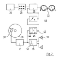
- 10 denotes a central clock for a keyboard. This provides the output frequency for a tone generator 12, which in turn works with a keypad 14. This is provided with additional keys or buttons for setting accompanying music and / or type of instrument, as is known per se.
- the output of the tone generator 12 is connected to one of the inputs of a stereo mixing amplifier 16 which drives the loudspeaker 18.
- a second input of the mixer amplifier 16 is connected to the output of a rhythm generator 20 which has two inputs.
- a first input receives a control signal specifying the rhythm type, which is provided by the keypad 14, and a second control signal specifying the rhythm clock frequency, which is derived from the output signal of the clock generator 10 by two frequency dividers 22, 24 connected in series.
- the two frequency dividers 22, 24 have an adjustable part ratio, as indicated by arrows.
- the connecting line between the two frequency dividers 22, 24 is connected to one input of a light control circuit 26. At its second input, the latter receives control signals which specify the amplitude and color of the light to be generated and are provided by an adjusting circuit 28. This in turn receives a raw signal that changes according to a predetermined pattern and is provided by a signal generator 30.
- a signal generator 30 This can be a sine generator running at a low frequency or a digitally operating voltage generator which e.g. stored in a ROM contains a slowly changing tone signal envelope.
- the light control circuit 26 According to the control signals given to its inputs, the light control circuit 26 generates light signals for a single or multi-color light generator 32, the frequency of which is predetermined by the output signal of the frequency divider 22 and the amplitude of which is predetermined by the setting circuit 28 and the signal generator 30.
- the keyboard according to FIG. 1 provides for the light signals to be used to control a sound generator 34, which e.g. in the simplest case provides three correspondingly controlled sine pulse sequences of different heights.
- the sound generator 34 can also have a more complicated structure, e.g. Provide sound signals with a wider spectrum depending on the light signals, e.g. Play triangles, wooden drums or the like.
- the output signal of the sound generator 34 is fed to a third input of the mixing amplifier 16, so that the light pulses generated by the light generator 32 have an acoustic mirror image.
- a CD player is shown schematically, which is also provided with a device for in-phase generation of higher-frequency light pulses.
- a compact disc 36 is rotated by an unplayed drive. Their recording tracks are read by a scanning head 38, which can be moved in the radial direction by a drive, which is also not shown.
- the tone generator 12 is now controlled by the output signal of the scanning head 38, the output signal of which is again transmitted to the loudspeakers 18 via the amplifier 16 is delivered.
- the output signal of the tone generator 12 is fed to a special waveform circuit 42 which is e.g. by connecting a filter 44 in series and a Schmidt trigger 46 driven by its output signal. If the filter 44 is set to low frequencies, 46 pulses are obtained at the output of the Schmidt trigger with the frequency of the low-frequency accompanying music of the piece of music read by the scanning head 38.
- the output signal of the waveform circuit 42 is fed back to one input of the light control circuit 26 via an adjustable frequency multiplier 48. Its second input again receives the output signal of the signal generator 30 modified by the setting circuit 28.
- the light generator 32 is now reproduced as glasses which each have three light-emitting diodes for the three basic colors on opaque glasses. Alternatively, one can only generate light of a single color and use only one light-emitting diode or several light-emitting diodes working at the same wavelength.
- a mixing stage can be used in the production of the compact disc or record or music cassette, one input of which is acted upon by the musical sound signal, while the other input is pure Receives sinusoidal signals which are modulated according to the control commands for the light generator.
- the control signals recorded in this way are then used again by the appropriately coordinated signal shaping circuit 42.
- these control signals can be heard in the loudspeakers 18, so that, in turn, simultaneous visual and acoustic stimuli are obtained.
- a blocking circuit 50 can be provided at the input of the amplifier 16, which blocks the sinusoidal light control signals.
- the control signals for the light generator 32 are now stored on the compact disc 36 on a separate recording track, and this is read out by a second scanning head 52.
- the output of the scanning head 52 is either connected directly to the input of the frequency multiplier 48, as shown, or, if the control signal is selected at a higher frequency, is also connected directly to the input of the light control circuit 26.
- the slowly variable output signal of the signal generator 30 via a power stage 54, which at the same time converts the amplitude-modulated envelope signal into a pulse-width-modulated fragrance control signal, actuates a solenoid valve 56, which is connected to a compressed air bottle 60 via a pressure regulator 58.
- a line connected to the outlet of the solenoid valve 56 dips into a volume 62 of liquid fragrance, so that the controlled release of fragrances takes place by controlling the rate of bubbling.
- fragrance is released in synchronization with the slow change in the amplitude of the light pulses.
- a music cassette 64 is used as the sound carrier, in which one of two stereo sound tracks 66, 68 is used for recording music, while the other is used for recording control signals for, for example, three different light sources. These three light signals lie in clearly separated audible areas of the spectrum, for example in the chamber tone, in the c 1 and in the f 1 . These signals are amplitude-modulated and are given back to the loudspeakers 18 via one of the stereo channels of the associated cassette player 70, which is only indicated schematically.
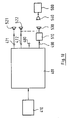
- a microphone 74 is mounted in a housing 72 and controls a three-color light generator 32 via control channels 76, 78, 80. These can each consist of a series connection of a filter 44, a Schmidt trigger 46, a frequency multiplier 48 and a light control circuit 26, as described in detail above with reference to FIG. 2.
- the signal obtained at the outputs of the filters 44 of the various control channels 76, 78, 80 is rectified in rectifier circuits 82, and with the slowly changing envelope of the light signals thus obtained, their amplitude when the light signals are input on the soundtrack 68, in addition to the light control circuits 26, controllable fragrance generators 84, 86, 88 are also actuated to release different fragrances.
- a color television 90 via a signal converter 92 with the light signals looped through by the light generator 32.
- the signal converter 92 converts the light signals into suitable video signals, similar to those that are output, for example, by a video camera or a video recorder.
- the use of the color television set 90 as a controllable light source has the advantage that a very large number of colors can be set very finely in the hue, in the intensity and the frequency and possibly also in the pattern.
- the light generator 32 can also be omitted and the color television 90 can be used as the only source providing visual stimuli.
- the fragrance generator 84 and corresponding to the fragrance generators 86, 88 each have a supply roll 94 of a fragrance carrier web 96, which consists of a paper web 98 and microcapsules 100 attached thereon and is wound on a core 102.
- the microcapsules can e.g. consist of gelatin and contain a fragrance.
- the supply roll 94 is freely rotatable on an axis 104.
- the scent carrier web 92 runs via a guide roller 106 into cooperating squeeze rollers 108, 110.
- the squeeze roller 110 is vertically movable and is biased by lateral springs 112 onto the squeeze roller 108 mounted in a frame 114.
- the stationary squeeze roller 108 is driven by a motor 116 driven, which receives the rectified output signal of the associated filter 44 via a power stage 118.
- the used fragrance carrier web 96 runs via a further guide roller 120 onto a core 122 (which has remained from a previously used supply roller) and which sits on a shaft 124 in a rotationally fixed manner. This is driven via a slip clutch 126 by a motor 128, which is activated by a feed circuit 130. The latter operates in dependence on the output signal of the power stage 118, so that the motor 128 is driven together with the motor 116, but at a different speed.
- mixed controllable fragrance sources according to FIG. 3 and controllable fragrance sources according to FIG. 5 can also be used in a relaxation device.
- oxygen or air enriched with oxygen can be used as the carrier gas bubbling through the fragrance 62.
- a small compressor can also be used instead of a compressed air bottle.
- a conventional record can also be used as a carrier for the sound signals and possibly the light signals.
- a multistimulation compact disc is shown at 210, on which three different recording areas are delimited: a track area 212, the which contains title information and organization data, a track area 214 which contains control signals for stimulus generators, as will be described in more detail later, and a track area 216 which contains the sound signals.
- the control unit 220 also excites a linear drive 222, by means of which a read head 224 is displaced in the radial direction over the compact disc 210.
- the read head 224 is connected to the input of an audio part 226, which has the structure customary for CD playback devices and provides 228 input signals for an amplifier on a line.
- line 228 is a multi-core line for the left and right stereo channels, but this need not be described in detail here.
- Further lines shown in FIG. 6, in particular lines for the transmission of digital signals, are also multi-core lines or data rails in practice, but this need not be described in detail here either.
- control unit 220 controls the audio part 226 in such a way that it switches this part off when the read head 224 is located above the track area 212 or the track area 214 or when signals from the compact disc 210 are not read out at all.
- the control unit 220 in turn operates as a function of a sensor 230, which responds when a new compact disc has been drawn into the player.
- An input unit 232 is also connected to the control unit 220, which is used to manually specify the operation of the Player is used, for example, to control a specific title.
- Another input of the control unit 220 is connected to the output of the read head 224 so that the control unit 220 can recognize when the signals emitted by the read head 224 represent title data, organizational data or control signals.
- an organization signal memory 234 is connected to the output of the read head 224, which stores the title and organization data when the read head 224 is moved over the track area 212 after inserting a compact disc 210.
- the control unit 220 activates the organization signal memory 234 for reading in this data.
- a control latch 236 is also connected to the read head 224. It is addressed when data is read in by the control unit 220, which stores the control signals for the various pieces recorded in the track area 216 in separate memory fields.
- control signal sequences for the individual pieces of music are separated by separating signals, each of which comprises a character sequence additionally characterizing the assignment.
- control signal sequences for the various pieces of music can be stored in sectors and tracks which are predetermined for a piece of music with a specific number, so that the assignment is also possible via the sector and track number.
- the control signals stored in each memory field contain all the information about how a plurality of stimulus generators are slowly and variably controlled in the entire course of the associated piece of music.
- the amount of data required for this is only small: OK if one assumes that a temporal resolution of only 10 seconds is desired, then with a typical total playing time of a compact disc of a maximum of 90 minutes and when controlling a stimulus generator with 16-bit commands, only about 1 kB of memory per stimulus generator is required.
- An inexpensive commercially available RAM with 64 kB is therefore sufficient for storing all control commands for a large number of stimulus generators.
- the control signal memory 236 is read out in accordance with the output signal of an addressing counter 238, which is reset by the control unit 220 at the beginning of a piece of music.
- the output signal of the addressing counter 238 forms the low-order part of the overall address of a control signal memory cell; the higher-order address part, which identifies the memory field, that is to say the respective piece of music, is also provided by the control unit 220 when it is read out.
- the addressing counter 238 is connected at its counter terminal to a free-running clock generator 240 which runs, for example, at a frequency of 0.1 Hz. This frequency can be reduced even further if there are only very slow-acting stimulus generators among the activated stimulus generators.
- a further modification of the exemplary embodiment according to FIG. 6 may consist in the fact that the recording medium is not a compact disc for music or speech pieces, but rather an image plate, with the audio part then 226 is replaced by an audio / video part.
- control signals for all recorded pieces of music were accommodated together in the track area 214.
- the control signals for the different pieces are separated either by interspersed separating and identification marks or by assigning predetermined sectors of the control signal tracks to the different pieces of music.
- the assigned sub-area 214-1, 214-2 etc. of the control signal track area 214 is placed in front. This means that the assigned control signals are automatically read in at the beginning of each piece of music.
- the control unit 220 recognizes these control signals from the corresponding command codes presented and passes the control signals to the control signal memory 236 as in the exemplary embodiment according to FIG. 6. In the case of the interleaving of the trace regions 214 and 216 shown in FIG. 7, this only needs to have a smaller capacity, or one obtains Given the memory size, a higher temporal resolution for the activation of the stimulus generators 244.
- the reading out of the control signals from the control signal memory 236 is also simplified; the memory cells are fully addressed by the addressing counter 238.
- the recording medium is a compact disc, and the sound signals are thus recorded on concentric tracks.
- the principle described can equally be applied to tape-shaped recording media, the analog of the embodiment according to FIG. 6 being contained therein there is that at the beginning of the band there is a block with the title and organization information, then a block with all control signals and then the blocks with the various pieces of music.
- the tape is played from the beginning, the titles and organizational data are then read out, then the entire control signals and then the successive pieces of music.
- the stimulus generators can be controlled with the same electronics and in the same way as described in FIG. 6.
- the exemplary embodiment according to FIG. 7 can also be transferred analogously to tape-shaped recording material: in front of each piece of music, the group of control signals is recorded which are required for controlling the various stimulus generators in the period in which the piece of music is running.
- FIG. 8 shows schematically a further modified way of recording the control signals on a magnetic tape 246.
- Short control signal blocks 250-i are inserted between longer audio signal sub-blocks 248-i of a piece of music, the beginning and end of which are each identified by marking signals.
- Such a magnetic tape can be read out using electronics which are only slightly modified compared to FIG. 6: an output of the control unit 220 is connected directly to the input of the decoder 242, and the circuits 236 to 240 are omitted.
- the control unit 220 operates in such a way that, when a control signal block 250 is recognized, it passes it through to the decoder 242 and blocks the audio part 226 for this short time.
- FIG. 248 in addition to a continuous sound signal track 248, one can be shown in FIG provide parallel continuous control signal track 250 which is read out by a separate read head. Its output can then be connected directly to the input of the decoder 242 (if appropriate with the interposition of suitable signal form circuits).
- the present invention can also be used in connection with other recording media than those already mentioned, e.g. with conventional sound films in which the control signals are either superimposed on the sound track or are provided on a separate control signal track or in a leader of the film e.g. are accommodated in some picture frames, which are read out via a diode line or a solid-state image converter when the film is stationary or moving slowly.
- Other possible recording media are mini discs, CCDs.
- FIG. 10 shows an exemplary embodiment of a fragrance generator which can release three different fragrances in a controlled manner.
- a tangential fan 254 which is driven by a motor 256, is arranged in a housing 252.
- the air emitted by the tangential fan 254 passes through circular arc-shaped openings 258 in a cover plate 260 of the housing 252.
- the headspace of the fragrance container 262 above the liquid level can be filled with a Pump 264 are pressurized, which is only indicated schematically in the drawing.
- the lower end of a spray tube 266 dips into the liquid volume, the discharge end of which can be opened and closed by a solenoid valve 268.
- the solenoid valves 268 are controlled to control the intensity of the fragrance emitted in pulse width modulation. This is done by a control circuit 270, which receives the fragrance control signal of the decoder 242 at an input. As soon as a fragrance control signal is present, the control circuit 270 starts the motor 256. Depending on the type of fragrance control signal transmitted, the control circuit 270 then determines which or which of the solenoid valves 268 are to be activated and how the relationship between the open time and the closing time is to be set.
- the fragrances emitted by the spray pipes 266 are quickly conveyed into the environment by the air curtain generated by the tangential fan 254.
- fragrance containers can be combined to form a block, only one common connector being provided for the various solenoid valves. The entire fragrance container unit can then be sold and replaced as such.
- Figure 12 shows a modified fragrance generator.
- a carrier tape 274 impregnated with fragrances is guided from a supply roll 272 via a deflection roller 276, a support plate 278 and a further deflection roller 280 onto a winding roller 282. Its axis is driven by a motor 284 which, via a decoder 286 to which the fragrance control signal is applied, a downstream D / A converter 288 and a power stage 290 in accordance with the intensity requested by the control signal the fragrance is driven.
- a further decoder 292 is connected to the input terminal of the fragrance generator and always provides an output signal when a non-zero fragrance delivery is requested.
- a feed circuit 294 for an ultrasound generator 296 is controlled by the output signal of the decoder 292. This is arranged above the carrier tape 274 so that the sound waves generated by it on the carrier tape 274 can destroy microcapsules which can be broken up by sound and which contain fragrances.
- the fragrance impregnation of the carrier tape 220 consists of a mixture of different microcapsules.
- a first type of microcapsule is shown at 298, which has a large diameter with a small wall thickness, that is to say can be broken up relatively easily by sound waves.
- microcapsules are shown which correspond in diameter to the microcapsules 298, but have larger wall thicknesses and are therefore more difficult to destroy.
- Microcapsules having a smaller diameter and having a porous wall material are shown at 302, as indicated in the enlargement at 304.
- the porosity of the wall material is low, so that only small amounts of fragrance diffuse through the wall without external influence.
- the capsule wall acts in a similar way to a pump membrane, so that there is a passage of fragrance.
- sound can be broken up differently easily Provide microcapsules that are filled with different fragrances. If the mechanical stability of the microcapsules is chosen to be small overall, they can also be broken up by audible sound, so that paper impregnated with microencapsulated fragrances can also be set up directly in front of the loudspeakers of a stereo system, the volume of the various types of microcapsules then being changed one after another can break open.
- the modified exemplary embodiment according to FIG. 13 largely corresponds to that according to FIG. 6.
- Corresponding parts are again provided with the same reference numerals and are not described again in detail.
- control signals are now read into the control signal memory 236 by a card reader 306, which cooperates with a control signal card 308. It can be a magnetic card, punch card or a card that carries a ROM. All control signals are stored on the control signal card 308, which were provided in the control signal trace area 214 of the compact disc 210 in the exemplary embodiment according to FIG. 6. This area is omitted in the exemplary embodiment according to FIG. 13, that is to say the compact disc 210 is a commercially available compact disc.
- control signal memory 236 is reversed between reading in and reading out, the counter 238 is reset and the various memory fields of the control signal memory 236 are selected by means of an input field 310, which thus replaces the control unit 220 insofar as its function is via the function of a normal CD player. Control unit goes out.
- the reading device can be replaced by an input field, on which the control signals are entered manually.
- control signal memory 236 for reading out is likewise actuated similarly to the exemplary embodiment according to FIG. 6, namely by means of a slowly counting counter 238.
- the control signals themselves are now derived directly from the video signals which a television receiver from an antenna 312 receives.
- An input circuit 314, which demodulates the signals, is connected to this.
- a control signal filter 316 is connected to its output. At its one output, the normal audio and video IF signals are forwarded to an audio / video part, designated overall by 318, which operates on a screen 320 and loudspeaker 322. Control signals for stimulus generators 244-i are obtained at the second output of the control signal filter 316.
- the filtering out by the control signal filter 316 takes place in such a way that it takes signal sequences, which are initiated and ended by a special separation signal, out of the stream of the signals.
- These filtered out signals are converted into binary signals in an analog / digital converter 324, and these are sent to a control unit 326.
- the control unit 326 first uses the separation signals to determine when a control signal transmission begins and ends. A corresponding control signal is provided on line 328. This signal is used to switch the control signal memory 236 between reading (W) and reading (R).
- the control unit 326 always provides a signal on a further line 330 when a new control signal, for example comprising 1 or 2 bytes, has been received.
- the control unit 326 provides in each case on a further line 332 a signal ready at the beginning of a control signal packet or at the end of a control signal packet.
- the counter 238 is reset by this signal.
- An AND gate 334 receives the clock signals on line 330.
- the activation signal of line 328 is applied to its second input via an inverter 336.
- the output of the AND gate 334 is connected to a first input of an OR gate 338, the output of which is connected to the counter terminal C of the counter 238.
- a second input of the OR gate 338 receives the output signals of the free-running clock generator 240 via an AND gate 340.
- the signal on line 328 is applied to the second input of the AND gate 340.
- the counter 238 counts up by one when reading in the control signal memory 236 whenever a new control signal has been received.
- the counter 238 counts up according to the pulses of the clock generator 240.
- the data input terminal DI of the control signal memory 236 is connected to an output terminal of the control unit 326, at which the digitized control signals are output.
- a data output terminal DO of the control signal memory 236 is again connected to the decoder 242, which selects the various fragrance generators 244-i and feeds them the corresponding control signals.
- control signals for the stimulus generators 244-i are preferably combined into a block which corresponds to the Contents of the control signal trace block 214 in the embodiment of Figure 6 corresponds. This block is emitted in a frequency gap at the beginning of a program and separated by the control signal filter 316.
- the control signals are then stored in the control signal memory 236 as described above. After the control signal block has been transmitted, the counter 238 is reset by the control unit 326, and the control signal memory 236 is now slowly read out, as explained in detail for the exemplary embodiment according to FIG. 6. This activates the stimulus generators at the desired points in the following program with the desired intensity.
- the data stream shown in Figure 15 is on a digital sound carrier, e.g. Disk or magnetic tape cassette, or on the accompanying audio track of an image carrier, e.g. Video disc or videotape cassette recorded.
- Each data block has the structure indicated in FIG. 16, in which the beginning of each data block can be identified by the "Sync" synchronization information provided as the "header".
- the "Sync" header is immediately followed by a sequence of samples of the digitized audio signal.
- a "bit assignment information" section and a "scale factors” section are inserted between the "Sync" header and the sequence of samples.
- each Data block a section reserved for additional information. If no additional information is provided, logical zeros are inserted into the relevant section of the data block. In the case of known digital sound carriers, the numbering and / or the title of the individual recordings is provided as additional information.
- control information for an optical, acoustic and / or fragrance-producing stimulus generator 500 (FIG. 17) is inserted in the section of each data block reserved for additional information in addition to or instead of the conventional additional information.
- This control information differs from the other additional information by correspondingly different coding or by suitable identification bits.
- the coding of the control information is adapted to the coding of the samples (subband or transformation coding), which advantageously enables the data of the digitized audio signal (including additional information) and the data of the control information according to the invention to be multiplexed.
- the outputs 422, 423, 424 and 425 are designed in the case of a split of the digitized audio signal into 16 sub-bands (sub-band coding) as a 16-fold line bundle with one line per sub-band.
- a separate series connection of blocks 430, 440 and 450 (FIG. 17) is provided for each sub-band, as indicated by three slashes in the feed and connecting lines to and between blocks 430, 440 and 450.
- the following consideration of the operation of blocks 430, 440 and 450 therefore applies in an identical manner to each subband.
- the sequence of the samples at the output 422 is fed to a bit allocation stage 430, the control input 431 of which is connected to the output 423.
- the irrelevance-reduced sampled values are de-quantized and leveled in the subsequent normalization stage 440 with the aid of the scale factors present there at control input 441.
- all 16 subband signals are fed to the common inverse filter 450, where they are combined to form a broadband, stereophonic digital signal.
- This stereophonic digital signal is converted in the digital / analog converter 460 into a stereophonic analog signal and stands with its left part L at output 471 and with its right component R at output 472 of decoder 401 are available.
- a stimulus generator 500 can be connected to the output 490, which is schematically divided into an optical part 501, an acoustic part 502 and a fragrance-producing part 503.
- the parts 501 to 503 of the stimulus generator are separate devices, the control inputs of which are each connected to the output 490 of the decoder 401 via a data bus connection.
- the exemplary configuration of parts 501 to 503 of stimulus generator 500 has already been explained above.
- fragrance bottles the closure of which is controlled by a digital valve information output 490 of decoder 401 via a magnetic valve.
- a so-called "light organ” with lamps of different colors can be used, which can be pivoted by a motor according to predetermined programs, in order to achieve constantly changing lighting effects in a room.
- Both the sequence of the colors and the movement of the individual color lamps can be controlled with the help of the control information at the output 490 of the decoder 401 in order, for example, to rhythmically change the lighting of a room to match the music.
- the scale factors are also used for control, which - as already mentioned - represent the envelope or envelope of the digitized audio signal.
- an acoustic coupling in the sense of a wireless remote control of the stimulus generator 500 is also possible.
- the control information at output 490 is fed to a sound generator 510, which generates a sound signal in the audible or inaudible (ultrasound) range.
- This sound signal is emitted either via a separate electroacoustic transducer 530 or - in the case of an audible sound signal - via one (521) of the speakers 521, 522 of the playback device, which are connected to the outputs 471 and 472 for the analog stereophonic sound signal via amplifiers (not shown) are.
- the stimulus generator 500 is provided with a microphone 540, which detects the audible or inaudible sound signal and supplies it as control information to the control input of the stimulus generator 500.
- An audible sound signal can be selected such that it can trigger a calming or stimulating effect on the listener, similar to the use of the envelope of the sound signal mentioned above.
Landscapes
- Health & Medical Sciences (AREA)
- Engineering & Computer Science (AREA)
- Bioinformatics & Cheminformatics (AREA)
- Animal Behavior & Ethology (AREA)
- General Health & Medical Sciences (AREA)
- Public Health (AREA)
- Veterinary Medicine (AREA)
- Life Sciences & Earth Sciences (AREA)
- Biomedical Technology (AREA)
- Pulmonology (AREA)
- Anesthesiology (AREA)
- Heart & Thoracic Surgery (AREA)
- Hematology (AREA)
- Multimedia (AREA)
- Signal Processing (AREA)
- Epidemiology (AREA)
- Pharmacology & Pharmacy (AREA)
- Disinfection, Sterilisation Or Deodorisation Of Air (AREA)
- Signal Processing For Digital Recording And Reproducing (AREA)
Abstract
Claims (29)
- Appareil pour produire des sons et/ou des images, comprenant une source de signaux utiles (210, 224 ; 312, 314) destinée à des signaux de son et/ou d'image et pourvue d'une unité de sortie (226, 228 ; 318 à 322) des sons et/ou des images reliée à cette source, comprenant une source de signaux de commande (210, 224, 236 à 240 ; 306, 308, 236 à 240 ; 316, 324, 326, 236 à 240), et comprenant au moins un générateur de stimulations (244) commandé par cette source, les signaux de commande du générateur de stimulations présentant une faible vitesse de modification en comparaison des signaux utiles, caractérisé par le fait que la source de signaux de commande comprend : un générateur de signaux de commande (214, 224 ; 306, 308 ; 312 à 316) et une mémoire (236) destinée aux signaux de commande et raccordée à lui, ainsi qu'une unité de commande (220 ; 310 ; 326) au moyen de laquelle la mémoire (236) destinée aux signaux de commande peut être activée en vue de la mise en mémoire et de la lecture de signaux de commande ; et par le fait que la mémoire (236) destinée aux signaux de commande est une mémoire numérique, et que ses emplacements de mémoire sont adressés lors de la lecture par un compteur d'adressage (238) dont la borne de comptage (C) est reliée à la sortie d'une horloge lente spontanée (240), tandis que l'adressage de la mémoire (236) destinée aux signaux de commande a lieu, lors de la mise en mémoire des signaux de commande, au moyen de l'unité de commande (220 ; 326) et en fonction des signaux de commande à l'entrée.
- Appareil selon la revendication 1, caractérisé par le fait que la source de signaux de commande (210, 224 ; 236 à 240 ; 306, 308, 236 à 240 ; 312 à 316, 236 à 240) excite une pluralité de générateurs de stimulations (244-i) par l'intermédiaire d'un décodeur de signaux de commande (242).
- Appareil selon la revendication 1 ou 2, dans lequel la source de signaux utiles comprend une partie réceptrice d'un appareil de radio et/ou de télévision (312, 314, 318), caractérisé par le fait que la source de signaux de commande comprend un filtre de signaux de commande (316) qui filtre des signaux initiés en fonction de la fréquence ou du temps ou par des signaux de séparation, à partir du courant des signaux fournis par un circuit d'entrée (314) de la partie réceptrice de l'appareil de radio et/ou de télévision (314, 318).
- Appareil selon la revendication 1 ou 2, dans lequel la source de signaux utiles comprend un support d'enregistrement de sons et/ou d'images dans lequel des pistes (216 ; 248) contenant des signaux de son et/ou d'image sont ménagées sur un matériau formant support (210 ; 246), caractérisé par le fait que des signaux de commande (214 ; 250) qui sont destinés à exciter le générateur de stimulations sont prévus en supplément sur le matériau formant support (210 ; 246).
- Appareil selon l'une des revendications 1 à 4, destiné à un support d'enregistrement dans lequel les groupes de pistes de signaux de commande qui sont à chaque fois associés à l'un des groupes de commande (216-i) des signaux de son et/ou d'image sont enregistrés d'une manière contiguë dans une zone de pistes de signaux de commande (214), cependant que les groupes de pistes de signaux de commande destinés à des morceaux différents sont séparés par des signaux de séparation et sont aussi identifiés de préférence, caractérisé par le fait qu'un adressage partiel de la mémoire (236) destinée aux signaux de commande a lieu lors de la lecture par l'unité de commande (230 310) selon le numéro du morceau qu'il faut jouer à chaque fois.
- Appareil selon l'une des revendications 1 à 5, caractérisé par le fait que le générateur de signaux de commande comporte un support de signaux de commande (308) et un appareil de lecture associé (306) ou une unité d'entrée de signaux de commande.
- Appareil selon l'une des revendications 1 à 6, caractérisé par le fait que la source de signaux de commande comporte des moyens de couplage des phases (10, 22, 24 ; 42, 48 ; 52, 48) qui sont alimentés par le signal utile de son et/ou d'image et qui fournissent sur leur sortie le signal de commande du générateur de stimulations présentant la relation prédéterminée entre les phases par rapport au signal utile de son et/ou d'image.
- Appareil selon la revendication 7, caractérisé par le fait que les moyens de couplage des phases comportent un circuit de filtrage (44) qui est alimenté par le signal de son, qui laisse passer par exemple les basses fréquences, dont l'entrée est alimentée par le signal utile de son et/ou d'image et dont la sortie fournit le signal de commande du générateur de stimulations.
- Appareil selon la revendication 7, caractérisé par le fait que la source de signaux utiles est un instrument de musique comportant un diviseur de fréquence (22, 24) qui prédétermine le rythme d'une musique d'accompagnement, dont l'entrée est reliée à une horloge spontanée (10) et dont la sortie est reliée à un générateur de tonalité (34), et par le fait que les moyens de couplage de phase sont constitués par le diviseur de fréquence (22, 24) qui fournit le signal de commande du générateur de stimulations sur une sortie intermédiaire.
- Appareil selon l'une des revendications 1 à 9, caractérisé par le fait que la source de signaux de commande comporte un diviseur de fréquence (22, 24) ou un multiplicateur de fréquence (48) qui est réglable, dont l'entrée est alimentée par le signal utile de son et/ou d'image et dont la sortie fournit le signal de commande du générateur de stimulations.
- Appareil selon l'une des revendications 1 à 10, caractérisé par le fait que la source de signaux de commande comporte un générateur de courbes-enveloppes (30) dont le signal de sortie est amené à un circuit de commande (26) qui est alimenté sur une autre entrée par le signal de commande du générateur de stimulations, ce signal étant modulé en amplitude en fonction du signal de sortie engendré par le générateur de courbes-enveloppes (30).
- Appareil selon l'une des revendications 1 à 11, caractérisé par le fait que l'un au moins des générateurs de stimulations pouvant être commandés est un générateur de parfum pouvant être commandé (56 à 62 ; 84 ; 244-i).
- Appareil selon la revendication 12, caractérisé par le fait que l'un au moins des générateurs de parfum pouvant être commandés comprend un générateur de gaz porteur pouvant être commandé (56 à 60), ainsi qu'un volume de parfum (62) à travers lequel le gaz porteur barbote.
- Appareil selon la revendication 13, caractérisé par le fait que le gaz porteur est de l'oxygène ou de l'air enrichi en oxygène.
- Appareil selon l'une des revendications 12 à 14, caractérisé par le fait que l'un au moins des générateurs de parfum pouvant être commandés comprend : un porte-parfum (96) constitué par un support (98) et au moins un parfum en microcapsules déposé sur celui-ci, ainsi qu'un dispositif (104 à 112) pour briser les capsules qui peut être commandé et qui coopère successivement avec des zones différentes du porte-parfum (96).
- Appareil selon la revendication 15, caractérisé par le fait que le porte-parfum (96) est en forme de bande, et qu'il est retiré d'un rouleau d'alimentation (94) par le dispositif pour briser les capsules qui comporte des rouleaux d'écrasement (108, 110).
- Appareil selon l'une des revendications 12 à 16, caractérisé par le fait que l'un au moins des générateurs de parfum (244-i) pouvant être commandés comprend : un réservoir (262-i) qui peut être mis sous pression (264) et qui est rempli d'un liquide contenant au moins un parfum, un tube de pulvérisation (266) qui plonge dans le liquide contenant les parfums et une soupape de sortie (268) qui peut être commandée et qui est montée dans le tube de pulvérisation (266).
- Appareil selon la revendication 17, caractérisé par le fait que plusieurs réservoirs (262-i) destinés à des liquides contenant des parfums sont reliés entre eux pour former un bloc de réservoirs.
- Appareil selon la revendication 17 ou 18, caractérisé par le fait qu'un ventilateur (254) est disposé au voisinage des tubes de pulvérisation (266).
- Appareil selon l'une des revendications 12 à 19, caractérisé par le fait que l'un au moins des générateurs de parfum (244-i) comprend : un substrat (274) et des microcapsules (298 à 302) qui sont disposées sur celui-ci et qui contiennent un parfum, la matière de la paroi des microcapsules étant fragile et pouvant être brisée par un son, ou étant élastique et poreuse, ainsi qu'un générateur de sons (296) qui dirige un son vers les microcapsules.
- Appareil selon la revendication 20, caractérisé par le fait que les microcapsules (298 à 302) sont constituées par un mélange de capsules différentes qui répondent à une fréquence différente et/ou à une intensité différente du son, comme par exemple des capsules dont la matière de la paroi est différente, des capsules dont le diamètre est différent ou des capsules dont l'épaisseur de la paroi est différente.
- Appareil selon la revendication 20 ou 21, caractérisé par le fait que le générateur de sons est un haut-parleur d'un dispositif de reproduction des sons.
- Appareil selon la revendication 20 ou 21, caractérisé par le fait que le générateur de sons est un générateur d'ultrasons (296) disposé au voisinage immédiat du substrat (274) qui porte les microcapsules (298 à 302).
- Appareil selon la revendication 22 ou 23, caractérisé par une paroi dure (278) qui est disposée derrière le substrat (274).
- Appareil selon l'une des revendications 20 à 24, caractérisé par le fait que le substrat (274) est en forme de bande, et qu'il est déplacé devant le générateur de sons (296) par un entraînement (284) en fonction du signal de commande du parfum.
- Appareil selon l'une des revendications 1 à 25, caractérisé par le fait que le signal de commande du générateur de stimulations commande en mène temps un générateur de tonalité (34) dont le signal de sortie est ajouté et mélangé au signal utile de son.
- Appareil selon l'une des revendications 1 à 26, caractérisé par le fait que l'un au moins (32) des générateurs de stimulations pouvant être commandés coopère avec un microphone de couplage (74) ou avec un détecteur de lumière, respectivement, celui-ci répondant à des signaux qui sont émis par un haut-parleur (18) ou par un générateur d'images, respectivement, et qui sont associés aux signaux de commande.
- Appareil selon la revendication 27, caractérisé par le fait qu'une unité de fonctionnement du générateur de stimulations, le microphone de couplage (74) et de préférence aussi le générateur de stimulations (32) lui-même sont logés dans un boîtier commun (72).
- Appareil selon l'une des revendications 1 à 28, caractérisé par le fait que l'un (32) des générateurs de stimulations est un téléviseur couleur (90), celui-ci étant alimenté par les signaux de commande par l'intermédiaire d'un convertisseur de signaux (92) qui transforme les signaux de commande en signaux vidéo.
Applications Claiming Priority (7)
| Application Number | Priority Date | Filing Date | Title |
|---|---|---|---|
| DE19924234926 DE4234926C2 (de) | 1992-10-16 | 1992-10-16 | Entspannungsgerät |
| DE4234926 | 1992-10-16 | ||
| DE19934305141 DE4305141A1 (de) | 1993-02-19 | 1993-02-19 | Gerät zum Erzeugen von Tönen und/oder Bildern |
| DE4305141 | 1993-02-19 | ||
| DE4313119 | 1993-04-22 | ||
| DE19934313119 DE4313119C2 (de) | 1993-04-22 | 1993-04-22 | Träger für digitalisierte Tonsignale mit digitaler Steuerungsinformation für einen Reizgenerator |
| PCT/EP1993/002858 WO1994009493A1 (fr) | 1992-10-16 | 1993-10-16 | Support d'enregistrement et appareil pour produire des sons et/ou des images |
Publications (2)
| Publication Number | Publication Date |
|---|---|
| EP0664919A1 EP0664919A1 (fr) | 1995-08-02 |
| EP0664919B1 true EP0664919B1 (fr) | 1997-05-14 |
Family
ID=27204334
Family Applications (1)
| Application Number | Title | Priority Date | Filing Date |
|---|---|---|---|
| EP93923479A Expired - Lifetime EP0664919B1 (fr) | 1992-10-16 | 1993-10-16 | Support d'enregistrement et appareil pour produire des sons et/ou des images |
Country Status (5)
| Country | Link |
|---|---|
| US (1) | US5734590A (fr) |
| EP (1) | EP0664919B1 (fr) |
| AU (1) | AU5334494A (fr) |
| DE (1) | DE59306470D1 (fr) |
| WO (1) | WO1994009493A1 (fr) |
Families Citing this family (139)
| Publication number | Priority date | Publication date | Assignee | Title |
|---|---|---|---|---|
| BR9601523A (pt) * | 1996-04-09 | 1998-03-24 | De Sousa Mauricio Araujo | Processo e aparelho para aromatização programada de ambientes |
| US6004516A (en) * | 1996-08-06 | 1999-12-21 | Illinois Institute Of Technology | Apparatus for generating odor upon electronic signal demand |
| JP3638201B2 (ja) * | 1996-09-17 | 2005-04-13 | 株式会社リコー | 制御型芳香出力装置および芳香シート |
| US6282458B1 (en) | 1996-09-17 | 2001-08-28 | Ricoh Company, Ltd. | Methods and systems for controlling olfactory stimuli |
| FR2765759B1 (fr) * | 1997-07-07 | 2002-06-07 | Ricoh Kk | Procede et systeme de production d'odeurs a partir de sources independamment liberables d'agents provocateurs d'odeur |
| US7038398B1 (en) * | 1997-08-26 | 2006-05-02 | Color Kinetics, Incorporated | Kinetic illumination system and methods |
| US20040052076A1 (en) * | 1997-08-26 | 2004-03-18 | Mueller George G. | Controlled lighting methods and apparatus |
| US6781329B2 (en) | 1997-08-26 | 2004-08-24 | Color Kinetics Incorporated | Methods and apparatus for illumination of liquids |
| US7385359B2 (en) | 1997-08-26 | 2008-06-10 | Philips Solid-State Lighting Solutions, Inc. | Information systems |
| US7764026B2 (en) * | 1997-12-17 | 2010-07-27 | Philips Solid-State Lighting Solutions, Inc. | Systems and methods for digital entertainment |
| US6548967B1 (en) * | 1997-08-26 | 2003-04-15 | Color Kinetics, Inc. | Universal lighting network methods and systems |
| US6777891B2 (en) * | 1997-08-26 | 2004-08-17 | Color Kinetics, Incorporated | Methods and apparatus for controlling devices in a networked lighting system |
| US6806659B1 (en) | 1997-08-26 | 2004-10-19 | Color Kinetics, Incorporated | Multicolored LED lighting method and apparatus |
| US6897624B2 (en) * | 1997-08-26 | 2005-05-24 | Color Kinetics, Incorporated | Packaged information systems |
| US6936978B2 (en) | 1997-08-26 | 2005-08-30 | Color Kinetics Incorporated | Methods and apparatus for remotely controlled illumination of liquids |
| US6967448B2 (en) | 1997-08-26 | 2005-11-22 | Color Kinetics, Incorporated | Methods and apparatus for controlling illumination |
| US6869204B2 (en) | 1997-08-26 | 2005-03-22 | Color Kinetics Incorporated | Light fixtures for illumination of liquids |
| US7231060B2 (en) * | 1997-08-26 | 2007-06-12 | Color Kinetics Incorporated | Systems and methods of generating control signals |
| US7186003B2 (en) | 1997-08-26 | 2007-03-06 | Color Kinetics Incorporated | Light-emitting diode based products |
| US7014336B1 (en) * | 1999-11-18 | 2006-03-21 | Color Kinetics Incorporated | Systems and methods for generating and modulating illumination conditions |
| US6774584B2 (en) | 1997-08-26 | 2004-08-10 | Color Kinetics, Incorporated | Methods and apparatus for sensor responsive illumination of liquids |
| US20030133292A1 (en) * | 1999-11-18 | 2003-07-17 | Mueller George G. | Methods and apparatus for generating and modulating white light illumination conditions |
| US7242152B2 (en) | 1997-08-26 | 2007-07-10 | Color Kinetics Incorporated | Systems and methods of controlling light systems |
| US7187141B2 (en) * | 1997-08-26 | 2007-03-06 | Color Kinetics Incorporated | Methods and apparatus for illumination of liquids |
| US7064498B2 (en) * | 1997-08-26 | 2006-06-20 | Color Kinetics Incorporated | Light-emitting diode based products |
| US6717376B2 (en) | 1997-08-26 | 2004-04-06 | Color Kinetics, Incorporated | Automotive information systems |
| US6624597B2 (en) | 1997-08-26 | 2003-09-23 | Color Kinetics, Inc. | Systems and methods for providing illumination in machine vision systems |
| US6720745B2 (en) | 1997-08-26 | 2004-04-13 | Color Kinetics, Incorporated | Data delivery track |
| US6965205B2 (en) * | 1997-08-26 | 2005-11-15 | Color Kinetics Incorporated | Light emitting diode based products |
| US7482764B2 (en) * | 1997-08-26 | 2009-01-27 | Philips Solid-State Lighting Solutions, Inc. | Light sources for illumination of liquids |
| US6975079B2 (en) * | 1997-08-26 | 2005-12-13 | Color Kinetics Incorporated | Systems and methods for controlling illumination sources |
| US7427840B2 (en) * | 1997-08-26 | 2008-09-23 | Philips Solid-State Lighting Solutions, Inc. | Methods and apparatus for controlling illumination |
| ES2133115B1 (es) * | 1997-10-01 | 2000-02-16 | Perex Agorreta Francisco J | Dispositivo reproductor o sintetizador de olores y aromas. |
| US7598686B2 (en) | 1997-12-17 | 2009-10-06 | Philips Solid-State Lighting Solutions, Inc. | Organic light emitting diode methods and apparatus |
| GB9900171D0 (en) * | 1999-01-05 | 1999-02-24 | Point 7 Design | Audio environment fragrancer |
| KR20020007351A (ko) * | 1999-04-07 | 2002-01-26 | 제프리 엠. 카덴 | 스테레오 시스템용 플래시 메모리 카드 어댑터 |
| TW462515U (en) * | 1999-08-04 | 2001-11-01 | Chiang Li | Network perfume device |
| WO2001024584A1 (fr) * | 1999-09-29 | 2001-04-05 | Color Kinetics, Inc. | Systemes et procedes d'etalonnage de la lumiere emise par des diodes lumineuses |
| US20050195598A1 (en) * | 2003-02-07 | 2005-09-08 | Dancs Imre J. | Projecting light and images from a device |
| US7838794B2 (en) * | 1999-12-28 | 2010-11-23 | Gsi Group Corporation | Laser-based method and system for removing one or more target link structures |
| US8217304B2 (en) * | 2001-03-29 | 2012-07-10 | Gsi Group Corporation | Methods and systems for thermal-based laser processing a multi-material device |
| RU2155090C1 (ru) * | 2000-01-10 | 2000-08-27 | Татевосян Ерванд Иосифович | Способ воспроизведения музыкальной звукозаписи с одновременной согласованной ароматизацией окружающей воздушной среды и устройство для его осуществления |
| US7049761B2 (en) | 2000-02-11 | 2006-05-23 | Altair Engineering, Inc. | Light tube and power supply circuit |
| US6800252B1 (en) * | 2000-03-06 | 2004-10-05 | Paul F. Jedzinski | Burstable scent beads |
| US7642730B2 (en) | 2000-04-24 | 2010-01-05 | Philips Solid-State Lighting Solutions, Inc. | Methods and apparatus for conveying information via color of light |
| PT1422975E (pt) * | 2000-04-24 | 2010-07-09 | Philips Solid State Lighting | Produto base de leds |
| US6556272B1 (en) | 2000-06-14 | 2003-04-29 | Multisen Technology, Inc. | Multimedia and scent storage medium and playback apparatus |
| US6602475B1 (en) | 2000-06-14 | 2003-08-05 | Multisen Technology, Inc. | Multimedia and scent storage medium and playback apparatus having electrostatic scent release |
| US6654664B1 (en) | 2000-06-14 | 2003-11-25 | Multisen Technology, Inc. | Multimedia and scent storage medium and playback apparatus |
| JP4773673B2 (ja) * | 2000-06-21 | 2011-09-14 | フィリップス ソリッド−ステート ライティング ソリューションズ インコーポレイテッド | オーディオ入力に応答して照明システムを制御する方法及び装置 |
| US7202613B2 (en) * | 2001-05-30 | 2007-04-10 | Color Kinetics Incorporated | Controlled lighting methods and apparatus |
| US7002617B1 (en) * | 2000-07-20 | 2006-02-21 | Robert Samuel Smith | Coordinated audio and visual omnidirectional recording |
| AU2001277185A1 (en) * | 2000-07-27 | 2002-02-13 | Color Kinetics Incorporated | Lighting control using speech recognition |
| US7042172B2 (en) * | 2000-09-01 | 2006-05-09 | Color Kinetics Incorporated | Systems and methods for providing illumination in machine vision systems |
| GB2367006A (en) * | 2000-09-20 | 2002-03-27 | Abraham Weissman | Aroma dispensing device |
| US7303300B2 (en) | 2000-09-27 | 2007-12-04 | Color Kinetics Incorporated | Methods and systems for illuminating household products |
| US6548025B1 (en) | 2000-11-08 | 2003-04-15 | Illinois Institute Of Technology | Apparatus for generating odor upon electronic signal demand |
| US20020114744A1 (en) * | 2000-11-16 | 2002-08-22 | Dah-Shiarn Chiao | Multimedia and scent storage cartridge design having electrostatic scent release and methods for using same |
| US6801003B2 (en) | 2001-03-13 | 2004-10-05 | Color Kinetics, Incorporated | Systems and methods for synchronizing lighting effects |
| US7038399B2 (en) | 2001-03-13 | 2006-05-02 | Color Kinetics Incorporated | Methods and apparatus for providing power to lighting devices |
| US7598684B2 (en) | 2001-05-30 | 2009-10-06 | Philips Solid-State Lighting Solutions, Inc. | Methods and apparatus for controlling devices in a networked lighting system |
| US20030026728A1 (en) * | 2001-08-02 | 2003-02-06 | Avram Vlad Iorgulescu | Substance and microclimate simulator |
| GB0123851D0 (en) | 2001-10-04 | 2001-11-28 | Pankhurst Design & Development | Dispersing fragrances |
| US7563695B2 (en) * | 2002-03-27 | 2009-07-21 | Gsi Group Corporation | Method and system for high-speed precise laser trimming and scan lens for use therein |
| US7358679B2 (en) * | 2002-05-09 | 2008-04-15 | Philips Solid-State Lighting Solutions, Inc. | Dimmable LED-based MR16 lighting apparatus and methods |
| AU2003233542B2 (en) * | 2002-05-13 | 2009-03-05 | S.C. Johnson & Son, Inc. | Coordinated emission of fragrance, light, and sound |
| GB0211898D0 (en) * | 2002-05-23 | 2002-07-03 | Koninkl Philips Electronics Nv | Controlling ambient light |
| US7023543B2 (en) * | 2002-08-01 | 2006-04-04 | Cunningham David W | Method for controlling the luminous flux spectrum of a lighting fixture |
| US7300192B2 (en) * | 2002-10-03 | 2007-11-27 | Color Kinetics Incorporated | Methods and apparatus for illuminating environments |
| US7469844B2 (en) * | 2002-11-08 | 2008-12-30 | S.C. Johnson & Son, Inc. | Diffusion device and method of diffusing |
| WO2004043502A1 (fr) * | 2002-11-08 | 2004-05-27 | S.C. Johnson & Son, Inc. | Distribution de substances volatiles multiples |
| US20040141321A1 (en) * | 2002-11-20 | 2004-07-22 | Color Kinetics, Incorporated | Lighting and other perceivable effects for toys and other consumer products |
| EP1468702A1 (fr) * | 2003-04-09 | 2004-10-20 | Creative Company S.r.l. | Dispositif de diffusion de substances dans l'air ambiant |
| US7178941B2 (en) * | 2003-05-05 | 2007-02-20 | Color Kinetics Incorporated | Lighting methods and systems |
| US7354172B2 (en) * | 2004-03-15 | 2008-04-08 | Philips Solid-State Lighting Solutions, Inc. | Methods and apparatus for controlled lighting based on a reference gamut |
| US7389943B2 (en) * | 2004-06-30 | 2008-06-24 | S.C. Johnson & Son, Inc. | Electromechanical apparatus for dispensing volatile substances with single dispensing mechanism and cartridge for holding multiple receptacles |
| US20060146126A1 (en) * | 2004-07-21 | 2006-07-06 | Yixin Guo | Electronic smell emission method and its system for television and movie |
| FR2880726A1 (fr) * | 2005-01-07 | 2006-07-14 | Yassine Jaafar Idrissi | Dispositif de diffusion olfactive via les frequences inaudibles et de mise en action des appareils a effets speciaux ou d'accompagnement |
| US20060191884A1 (en) * | 2005-01-21 | 2006-08-31 | Johnson Shepard D | High-speed, precise, laser-based material processing method and system |
| BE1016577A3 (fr) * | 2005-03-31 | 2007-02-06 | Philippe Haumann | Systeme de bien-etre. |
| KR20080009685A (ko) * | 2005-04-12 | 2008-01-29 | 에스.씨. 존슨 앤드 선, 인코포레이티드 | 확산기구 및 확산방법 |
| US7622073B2 (en) * | 2005-04-12 | 2009-11-24 | S.C. Johnson & Son, Inc. | Apparatus for and method of dispensing active materials |
| US7318778B2 (en) * | 2005-06-11 | 2008-01-15 | Owens Mark R | Golf putter with removable laser |
| US20070215575A1 (en) * | 2006-03-15 | 2007-09-20 | Bo Gu | Method and system for high-speed, precise, laser-based modification of one or more electrical elements |
| US20080038706A1 (en) * | 2006-08-08 | 2008-02-14 | Siemens Medical Solutions Usa, Inc. | Automated User Education and Training Cognitive Enhancement System |
| RU2502135C2 (ru) | 2007-05-24 | 2013-12-20 | Конинклейке Филипс Электроникс Н.В. | Система и способ для автоматического создания определенной атмосферы посредством управления вкладами сенсорно воспринимаемых стимулирующих средств |
| NL2000926C2 (nl) * | 2007-10-12 | 2009-04-15 | Jan Jonquiere | Licht- en geluidszuil. |
| US10321528B2 (en) | 2007-10-26 | 2019-06-11 | Philips Lighting Holding B.V. | Targeted content delivery using outdoor lighting networks (OLNs) |
| US8320751B2 (en) * | 2007-12-20 | 2012-11-27 | S.C. Johnson & Son, Inc. | Volatile material diffuser and method of preventing undesirable mixing of volatile materials |
| US8118447B2 (en) | 2007-12-20 | 2012-02-21 | Altair Engineering, Inc. | LED lighting apparatus with swivel connection |
| US7712918B2 (en) | 2007-12-21 | 2010-05-11 | Altair Engineering , Inc. | Light distribution using a light emitting diode assembly |
| USD584809S1 (en) | 2008-02-04 | 2009-01-13 | S. C. Johnson & Son, Inc. | Dispensing device |
| US8360599B2 (en) | 2008-05-23 | 2013-01-29 | Ilumisys, Inc. | Electric shock resistant L.E.D. based light |
| US7976196B2 (en) | 2008-07-09 | 2011-07-12 | Altair Engineering, Inc. | Method of forming LED-based light and resulting LED-based light |
| US7946729B2 (en) | 2008-07-31 | 2011-05-24 | Altair Engineering, Inc. | Fluorescent tube replacement having longitudinally oriented LEDs |
| US8674626B2 (en) | 2008-09-02 | 2014-03-18 | Ilumisys, Inc. | LED lamp failure alerting system |
| US8256924B2 (en) | 2008-09-15 | 2012-09-04 | Ilumisys, Inc. | LED-based light having rapidly oscillating LEDs |
| US8444292B2 (en) | 2008-10-24 | 2013-05-21 | Ilumisys, Inc. | End cap substitute for LED-based tube replacement light |
| US8653984B2 (en) | 2008-10-24 | 2014-02-18 | Ilumisys, Inc. | Integration of LED lighting control with emergency notification systems |
| US8214084B2 (en) | 2008-10-24 | 2012-07-03 | Ilumisys, Inc. | Integration of LED lighting with building controls |
| US8324817B2 (en) | 2008-10-24 | 2012-12-04 | Ilumisys, Inc. | Light and light sensor |
| US7938562B2 (en) | 2008-10-24 | 2011-05-10 | Altair Engineering, Inc. | Lighting including integral communication apparatus |
| US8901823B2 (en) | 2008-10-24 | 2014-12-02 | Ilumisys, Inc. | Light and light sensor |
| US8556452B2 (en) | 2009-01-15 | 2013-10-15 | Ilumisys, Inc. | LED lens |
| US8362710B2 (en) | 2009-01-21 | 2013-01-29 | Ilumisys, Inc. | Direct AC-to-DC converter for passive component minimization and universal operation of LED arrays |
| US8664880B2 (en) | 2009-01-21 | 2014-03-04 | Ilumisys, Inc. | Ballast/line detection circuit for fluorescent replacement lamps |
| US8330381B2 (en) | 2009-05-14 | 2012-12-11 | Ilumisys, Inc. | Electronic circuit for DC conversion of fluorescent lighting ballast |
| US8299695B2 (en) | 2009-06-02 | 2012-10-30 | Ilumisys, Inc. | Screw-in LED bulb comprising a base having outwardly projecting nodes |
| EP2446715A4 (fr) | 2009-06-23 | 2013-09-11 | Ilumisys Inc | Dispositif d'éclairage comprenant des del et un système de commande d'alimentation à découpage |
| CN102473031A (zh) * | 2009-07-15 | 2012-05-23 | 皇家飞利浦电子股份有限公司 | 用于基于第一模态控制第二模态的方法 |
| US9473813B2 (en) * | 2009-12-31 | 2016-10-18 | Infosys Limited | System and method for providing immersive surround environment for enhanced content experience |
| EP2553332B1 (fr) | 2010-03-26 | 2016-03-23 | iLumisys, Inc. | Lampe à del interne-externe |
| EP2553320A4 (fr) | 2010-03-26 | 2014-06-18 | Ilumisys Inc | Lampe à del comprenant un générateur thermoélectrique |
| US9057493B2 (en) | 2010-03-26 | 2015-06-16 | Ilumisys, Inc. | LED light tube with dual sided light distribution |
| USD639923S1 (en) | 2010-04-15 | 2011-06-14 | S.C. Johnson & Son, Inc. | Dispensing device |
| US8454193B2 (en) | 2010-07-08 | 2013-06-04 | Ilumisys, Inc. | Independent modules for LED fluorescent light tube replacement |
| US8596813B2 (en) | 2010-07-12 | 2013-12-03 | Ilumisys, Inc. | Circuit board mount for LED light tube |
| EP2633227B1 (fr) | 2010-10-29 | 2018-08-29 | iLumisys, Inc. | Mécanismes pour réduire le risque d'électrocution pendant l'installation d'un tube fluorescent |
| US8870415B2 (en) | 2010-12-09 | 2014-10-28 | Ilumisys, Inc. | LED fluorescent tube replacement light with reduced shock hazard |
| US9072171B2 (en) | 2011-08-24 | 2015-06-30 | Ilumisys, Inc. | Circuit board mount for LED light |
| US11493998B2 (en) | 2012-01-17 | 2022-11-08 | Ultrahaptics IP Two Limited | Systems and methods for machine control |
| US8693731B2 (en) | 2012-01-17 | 2014-04-08 | Leap Motion, Inc. | Enhanced contrast for object detection and characterization by optical imaging |
| US12260023B2 (en) | 2012-01-17 | 2025-03-25 | Ultrahaptics IP Two Limited | Systems and methods for machine control |
| US9184518B2 (en) | 2012-03-02 | 2015-11-10 | Ilumisys, Inc. | Electrical connector header for an LED-based light |
| DE102012008396A1 (de) * | 2012-04-27 | 2013-10-31 | Mediaworkxx GmbH | Verfahren und Vorrichtung zur Erzeugung eines zur Wiedergabe eines Medieninhalts synchronen Kontrollsignals |
| WO2014008463A1 (fr) | 2012-07-06 | 2014-01-09 | Ilumisys, Inc. | Ensemble d'alimentation électrique pour tube lumineux à del |
| US9271367B2 (en) | 2012-07-09 | 2016-02-23 | Ilumisys, Inc. | System and method for controlling operation of an LED-based light |
| US9285084B2 (en) | 2013-03-14 | 2016-03-15 | Ilumisys, Inc. | Diffusers for LED-based lights |
| WO2014200589A2 (fr) | 2013-03-15 | 2014-12-18 | Leap Motion, Inc. | Détermination d'informations de position pour un objet dans l'espace |
| US9460404B2 (en) * | 2013-07-10 | 2016-10-04 | Scentair Technologies, Llc | Scent delivery system scheduling |
| JPWO2015025511A1 (ja) * | 2013-08-23 | 2017-03-02 | パナソニック インテレクチュアル プロパティ コーポレーション オブ アメリカPanasonic Intellectual Property Corporation of America | 匂い再生装置 |
| US9267650B2 (en) | 2013-10-09 | 2016-02-23 | Ilumisys, Inc. | Lens for an LED-based light |
| US9574717B2 (en) | 2014-01-22 | 2017-02-21 | Ilumisys, Inc. | LED-based light with addressed LEDs |
| US9510400B2 (en) | 2014-05-13 | 2016-11-29 | Ilumisys, Inc. | User input systems for an LED-based light |
| US10075757B2 (en) * | 2014-09-19 | 2018-09-11 | Foundation Partners Group, Llc | Multi-sensory environment room |
| US10161568B2 (en) | 2015-06-01 | 2018-12-25 | Ilumisys, Inc. | LED-based light with canted outer walls |
| DE102017200601B4 (de) | 2017-01-17 | 2019-02-14 | Audi Ag | Verfahren zur Anregung des aufsteigenden retikulären Aktivierungssystems einer Person in einem Kraftfahrzeug sowie Vorrichtung |
| ES2718220A1 (es) | 2017-12-28 | 2019-06-28 | Zobele Espana Sa | Difusor de sustancias volátiles |
| US11058789B2 (en) * | 2018-07-16 | 2021-07-13 | Joshua Roehrig | Scent dispenser device and a head mounting device with the scent dispenser device |
Family Cites Families (28)
| Publication number | Priority date | Publication date | Assignee | Title |
|---|---|---|---|---|
| DE1566652B2 (de) * | 1967-04-22 | 1971-01-14 | Saba Schwarzwalder Apparate-Bau-Anstalt August Schwer Söhne GmbH, 773OVilhngen | Gerat zur wahlweisen Benutzung als Rundfunk-Empfangsgerät oder als Schlaf therapiegerät |
| US3494505A (en) * | 1968-07-09 | 1970-02-10 | Minnesota Mining & Mfg | Fragrance sampling means and method |
| JPS6038506B2 (ja) * | 1978-06-17 | 1985-09-02 | 三菱鉱業セメント株式会社 | コンクリ−トの輸送方法 |
| JPS5525276A (en) * | 1978-08-12 | 1980-02-22 | Minoru Uchiumi | Stereoscopic television |
| US4315502A (en) * | 1979-10-11 | 1982-02-16 | Gorges Denis E | Learning-relaxation device |
| US4573472A (en) * | 1981-09-25 | 1986-03-04 | Yoshihiro Ito | Autogenic training and treating apparatus |
| AU2144283A (en) * | 1982-11-26 | 1984-05-31 | Rupert William Wallace | Film signals releasing aromas |
| US4629604A (en) * | 1983-03-21 | 1986-12-16 | Donald Spector | Multi-aroma cartridge player |
| JPS6141229A (ja) * | 1984-07-31 | 1986-02-27 | Tamapatsuku Kk | 芳香発生機構付音響再生装置 |
| US4952024A (en) * | 1986-08-29 | 1990-08-28 | Gale Thomas S | Three-dimensional sight and sound reproduction apparatus for individual use |
| US4753148A (en) * | 1986-12-01 | 1988-06-28 | Johnson Tom A | Sound emphasizer |
| JPH01199385A (ja) * | 1988-02-03 | 1989-08-10 | Yamaha Corp | ソース再生装置 |
| US5113738A (en) * | 1988-05-25 | 1992-05-19 | Darwin Krucoff | Recorded music enhancement system |
| JPH027969A (ja) * | 1988-06-28 | 1990-01-11 | Toshiba Corp | 芳香装置 |
| NL8802291A (nl) * | 1988-09-16 | 1990-04-17 | Koninkl Philips Electronics Nv | Inrichting voor het verzenden van datawoorden welke een gedigitaliseerde analoog signaal vertegenwoordigen en een inrichting voor het ontvangen van de verzonden datawoorden. |
| JP2889614B2 (ja) * | 1989-10-03 | 1999-05-10 | 株式会社テクノ菱和 | 芳香供給装置 |
| JPH03163797A (ja) * | 1989-11-20 | 1991-07-15 | Brother Ind Ltd | コンパクトディスク再生装置 |
| JPH03163796A (ja) * | 1989-11-20 | 1991-07-15 | Brother Ind Ltd | コンパクトディスクとこれを用いた照明制御装置 |
| US4988557A (en) * | 1989-12-08 | 1991-01-29 | Minnesota Mining And Manufacturing Company | Fragrance sampling device |
| DE4003477A1 (de) * | 1990-02-06 | 1991-08-08 | Stefan Reich | Verfahren zur ton- und lichtreizung |
| DE4003476A1 (de) * | 1990-02-06 | 1991-08-08 | Stefan Reich | Geraet zur akustischen stimulation |
| JPH0422369A (ja) * | 1990-05-17 | 1992-01-27 | Matsushita Electric Ind Co Ltd | 体感制御装置 |
| JPH0458956A (ja) * | 1990-06-28 | 1992-02-25 | Matsushita Electric Ind Co Ltd | 芳香装置 |
| DE4033076A1 (de) * | 1990-10-18 | 1992-04-23 | Bruno Gruber | Wirkstoffspender |
| FR2670568B1 (fr) * | 1990-12-18 | 1993-05-28 | Parant Jean Pierre | Dispositif pour le traitement de l'air de locaux. |
| PT97283A (pt) * | 1991-04-08 | 1992-06-30 | Alcino Gomes Dos Santos | Recriador de ambientes cenicos |
| JPH05109253A (ja) * | 1991-10-16 | 1993-04-30 | Toshiba Corp | 芳香機能付きデータ再生装置 |
| US5513129A (en) * | 1993-07-14 | 1996-04-30 | Fakespace, Inc. | Method and system for controlling computer-generated virtual environment in response to audio signals |
-
1993
- 1993-10-16 EP EP93923479A patent/EP0664919B1/fr not_active Expired - Lifetime
- 1993-10-16 AU AU53344/94A patent/AU5334494A/en not_active Abandoned
- 1993-10-16 DE DE59306470T patent/DE59306470D1/de not_active Expired - Fee Related
- 1993-10-16 WO PCT/EP1993/002858 patent/WO1994009493A1/fr not_active Ceased
- 1993-10-16 US US08/416,854 patent/US5734590A/en not_active Expired - Fee Related
Also Published As
| Publication number | Publication date |
|---|---|
| DE59306470D1 (de) | 1997-06-19 |
| AU5334494A (en) | 1994-05-09 |
| EP0664919A1 (fr) | 1995-08-02 |
| WO1994009493A1 (fr) | 1994-04-28 |
| US5734590A (en) | 1998-03-31 |
Similar Documents
| Publication | Publication Date | Title |
|---|---|---|
| EP0664919A1 (fr) | Support d'enregistrement et appareil pour produire des sons et/ou des images. | |
| Hayes | Vertical-Interval Encoding for the Recordable Laser Videodisc | |
| EP1000646B1 (fr) | Procédé et dispositif de diffusion d'odeurs en rapport avec des événements ou des scènes déterminées pendant des représentations cinématographiques et similaires | |
| DE3886618T2 (de) | Optische platte. | |
| DE3853325T2 (de) | Automatisierte Stereo-Synthese-Vorrichtung und -Verfahren für Ton-Bildprogramme. | |
| DE69318038T2 (de) | Aufzeichnungsmedium, das verschiedene sprachen verarbeiten kann und wiedergabevorrichtung | |
| DE2207071A1 (de) | Verfahren zum Aufzeichnen und Wiedergeben von Video-Informationssignalen | |
| CA2200577A1 (fr) | Procede interactif de programmation | |
| DE19924337A1 (de) | Verfahren und Vorrichtung zur Erzeugung und Steuerung einer simulierten Musikkonzert-Erfahrung | |
| DE68919592T2 (de) | Gerät zum Übermitteln von Steuercodes zu einem Schallfeldwiedergabegerät. | |
| DE2344340C3 (de) | Signalübertragungssystem insbesondere Stehbildübertragungssystem | |
| DE4305141A1 (de) | Gerät zum Erzeugen von Tönen und/oder Bildern | |
| DE1194183B (de) | Vorrichtung zum akustisch-optischen Unterricht | |
| DE4234926C2 (de) | Entspannungsgerät | |
| US5914914A (en) | Method and apparatus for storing and presenting visual and audible information to an individual | |
| DE3939369A1 (de) | Ausstellungssystem | |
| DE4313119C2 (de) | Träger für digitalisierte Tonsignale mit digitaler Steuerungsinformation für einen Reizgenerator | |
| Eidsvik | Background tracks in recent cinema | |
| EP1260255A1 (fr) | Procede de reproduction d'enregistrement musical simultanement a l'aromatisation coordonnee de l'atmosphere ambiante et dispositif associe | |
| DE2823466A1 (de) | Erzeugung eines niederfrequenz- ton-programms | |
| DE4141575C2 (de) | Verfahren und Schaltungsanordnung zur quasidialoggesteuerten Darstellung eines TV-Programms | |
| US5689477A (en) | Method and apparatus for storing and presenting visual and audible information to an individual | |
| CH674591A5 (fr) | ||
| DE818446C (de) | Tonaufzeichnungs- und Abtastgeraet fuer elektroakustische Glockengelaeute | |
| DE2828050A1 (de) | Magnetbandgeraet und/oder magnettonprojektor mit programmsteuerung |
Legal Events
| Date | Code | Title | Description |
|---|---|---|---|
| PUAI | Public reference made under article 153(3) epc to a published international application that has entered the european phase |
Free format text: ORIGINAL CODE: 0009012 |
|
| 17P | Request for examination filed |
Effective date: 19950418 |
|
| AK | Designated contracting states |
Kind code of ref document: A1 Designated state(s): DE |
|
| 17Q | First examination report despatched |
Effective date: 19950727 |
|
| GRAG | Despatch of communication of intention to grant |
Free format text: ORIGINAL CODE: EPIDOS AGRA |
|
| GRAH | Despatch of communication of intention to grant a patent |
Free format text: ORIGINAL CODE: EPIDOS IGRA |
|
| GRAH | Despatch of communication of intention to grant a patent |
Free format text: ORIGINAL CODE: EPIDOS IGRA |
|
| GRAA | (expected) grant |
Free format text: ORIGINAL CODE: 0009210 |
|
| AK | Designated contracting states |
Kind code of ref document: B1 Designated state(s): DE |
|
| REF | Corresponds to: |
Ref document number: 59306470 Country of ref document: DE Date of ref document: 19970619 |
|
| PLBE | No opposition filed within time limit |
Free format text: ORIGINAL CODE: 0009261 |
|
| STAA | Information on the status of an ep patent application or granted ep patent |
Free format text: STATUS: NO OPPOSITION FILED WITHIN TIME LIMIT |
|
| 26N | No opposition filed | ||
| PGFP | Annual fee paid to national office [announced via postgrant information from national office to epo] |
Ref country code: DE Payment date: 20031222 Year of fee payment: 11 |
|
| PG25 | Lapsed in a contracting state [announced via postgrant information from national office to epo] |
Ref country code: DE Free format text: LAPSE BECAUSE OF NON-PAYMENT OF DUE FEES Effective date: 20050503 |