EP0664923B1 - Verfahren und vorrichtung zum formen der anschlussbeinchen von integrierten schaltkreisen - Google Patents
Verfahren und vorrichtung zum formen der anschlussbeinchen von integrierten schaltkreisen Download PDFInfo
- Publication number
- EP0664923B1 EP0664923B1 EP93924036A EP93924036A EP0664923B1 EP 0664923 B1 EP0664923 B1 EP 0664923B1 EP 93924036 A EP93924036 A EP 93924036A EP 93924036 A EP93924036 A EP 93924036A EP 0664923 B1 EP0664923 B1 EP 0664923B1
- Authority
- EP
- European Patent Office
- Prior art keywords
- leads
- housing
- jaws
- bending
- legs
- Prior art date
- Legal status (The legal status is an assumption and is not a legal conclusion. Google has not performed a legal analysis and makes no representation as to the accuracy of the status listed.)
- Expired - Lifetime
Links
Images

Classifications
-
- H—ELECTRICITY
- H05—ELECTRIC TECHNIQUES NOT OTHERWISE PROVIDED FOR
- H05K—PRINTED CIRCUITS; CASINGS OR CONSTRUCTIONAL DETAILS OF ELECTRIC APPARATUS; MANUFACTURE OF ASSEMBLAGES OF ELECTRICAL COMPONENTS
- H05K13/00—Apparatus or processes specially adapted for manufacturing or adjusting assemblages of electric components
- H05K13/0092—Treatment of the terminal leads as a separate operation
-
- H—ELECTRICITY
- H10—SEMICONDUCTOR DEVICES; ELECTRIC SOLID-STATE DEVICES NOT OTHERWISE PROVIDED FOR
- H10W—GENERIC PACKAGES, INTERCONNECTIONS, CONNECTORS OR OTHER CONSTRUCTIONAL DETAILS OF DEVICES COVERED BY CLASS H10
- H10W99/00—Subject matter not provided for in other groups of this subclass
-
- H—ELECTRICITY
- H05—ELECTRIC TECHNIQUES NOT OTHERWISE PROVIDED FOR
- H05K—PRINTED CIRCUITS; CASINGS OR CONSTRUCTIONAL DETAILS OF ELECTRIC APPARATUS; MANUFACTURE OF ASSEMBLAGES OF ELECTRICAL COMPONENTS
- H05K13/00—Apparatus or processes specially adapted for manufacturing or adjusting assemblages of electric components
-
- H—ELECTRICITY
- H10—SEMICONDUCTOR DEVICES; ELECTRIC SOLID-STATE DEVICES NOT OTHERWISE PROVIDED FOR
- H10W—GENERIC PACKAGES, INTERCONNECTIONS, CONNECTORS OR OTHER CONSTRUCTIONAL DETAILS OF DEVICES COVERED BY CLASS H10
- H10W70/00—Package substrates; Interposers; Redistribution layers [RDL]
- H10W70/01—Manufacture or treatment
- H10W70/04—Manufacture or treatment of leadframes
- H10W70/048—Mechanical treatments, e.g. punching, cutting, deforming or cold welding
Definitions
- the invention relates to a method with the The preamble of claim 1 features and specified of a device with the in the preamble of the claims 6 or 7 specified characteristics.
- Integrated Circuits are mainly built on carrier strips and with encapsulated in a plastic housing.
- the carrier strip is a metal edge on which the structures of the connecting legs can be formed by etching or stamping.
- the Leads are in on the side of the housing arranged on a common level.
- the first level connection legs in a suitable one Shape to be bent.
- the housings are still over Bridges connected to the carrier strip at the corners of the housing.
- the bending tools for the legs are therefore precision tools. Particularly high demands on precision of the bending tools represent modern, highly integrated ICs with well over a hundred connecting legs.
- the legs are usually Z-shaped with two approximations bent at right angles.
- the connecting legs close to the housing against to clamp a bending die and with a bending punch approx. 45 degrees down against the complementary bending surface first bend the die diagonally.
- the ICs are then still connected to the lead frame, transferred into a neighboring die, in which the legs between a bending die and oblique bending stamps in their final Shape to be bent.
- the bending die one of the desired Z-shape of the legs Form in which an upper stamp obliquely from above, with its tip against the top of the form the bending die is straightened, pushed in and thereby the legs in the recess of the bending shape of the Die presses.
- EP-A-0 513 425 are a device according to the preamble of claim 7 and a method of forming the leads known from integrated circuits, in which the Legs of the integrated circuit at some distance jammed from its housing and then the Legs while maintaining the clamp along an arched path leading into one at right angles containing the respective legs to a level containing the legs level is to be positively guided.
- the disadvantage of this is that due to this Bending the oaks into free space a repeatable, even bending process is not or is difficult to achieve.
- JP-A-01 309 725 is a device known according to the preamble of claim 6.
- the present invention is based on the object the accuracy in bending the leads from IC's increase and the need for tool changes for the purpose of cleaning tin deposits on the bending inserts of the tools.
- the present invention makes a departure from that previously common procedure, the legs in one To form a die by simply using a punch pressed into a recess in a die shape become; rather the legs are at their free ends clamped in a clamping tool and the clamped Ends of the legs then along an arc Path, without lateral deviation, positively guided.
- This will ensure that the ends of the legs, the for the automated soldering of the IC's on circuit board in a specific position in a common Must be level, positively guided by the clamping tool and - unlike the state of the art - no possibility of lateral evasion during the Bending process so that they are in their predetermined position inevitably reach.
- the clamping tool preferably performed so that the alignment the pinched ends of the legs are preserved, while being forced sideways on the arched path led, i.e. the ends of the legs remain parallel to the common plane in which it was originally have been lying.
- the legs Due to the coating with tin, the legs are generally somewhat uneven. However, to ensure that the legs on all four sides of the IC package can be firmly gripped at the same time, preferably so that the legs are not worked on all four Sides of the housing together, but separate and independent seized from each other by separate clamping tools and be bent.
- the device according to the invention is used as a clamping tool two jaws, which next to the housing act on the underside and the top of the legs. They are arranged rotatable about axes parallel to the common plane in which the legs originally lying, and perpendicular to the longitudinal extent the legs run with the axes transverse are slidably mounted to the common plane, and not individually against each other, but together while maintaining the clamp.
- the common Level where the legs originally lie, is present indirectly in the device according to the invention, defined by the facility for admission of the housing in a predetermined position.
- the legs in the Bending free space is a repeatable, uniform bending process, that of each other produces similarly shaped connecting legs, advantageous, when the bending jaws towards its clamping surface against the establishment of the housing receptacle subsequently has a bending surface to which the legs attach themselves when Bending can create, so this bending surface, which preferably convex rounded, the shape of the curved Certainly.
- This bending surface preferably works together with a counter shape, which forms a bending shape has complementary surface area against which the Bending jaw is moved with its bending surface, so that at the end of the bending process, the legs between the Bending surface and the complementary surface area clamped are, which also means the central area of the connecting legs inevitably takes a predetermined shape, but without any friction between the legs and the bending surface on one side and the complementary one Surface area on the other hand, so the benefits of the invention resulting from the positive control of the pinched ends of the legs result in full remain.
- the complementary surface area is expedient on the device for housing mounting as a bending die shape educated.
- both jaws To trigger the bending process by moving the jaws lengthways, it is not necessary for both jaws to be one have their own actuating device, rather it is sufficient if only one of the jaws by an actuator can be pushed forward and the other jaw springs back is stored so that it e.g. withdraws against a spring force, when the first jaw is advanced. Naturally the spring force must be sufficient to the ends to hold the legs between the cheeks. Conveniently it is the jaws equipped with the bending surface, which can be advanced by the actuator. A swivel drive is preferably also provided for this jaw provided by which of the jaws against the device to accommodate the housing and the bending die shape can also be pressed.
- This swivel drive is not needed to get that out of the two cheeks formed clamping tool along the predetermined arcuate Moving way but it should enable then when the bending process is essentially completed and the legs between the bending surface and the complementary surface to press or even bend something if that in the individual application appropriate or desirable should be.
- the swivel drive is preferably cushioned. Consequently the forces that occur can easily be achieved via the spring force be determined.
- the device shown in Figure 1 has two guide housings 1 and 2, which are spaced apart are. Both guide housings 1 and 2 are on a common one Tool guide arranged and can be independent of each other be moved in the longitudinal direction (arrows 38 and 39). Located in the free space between the two housings two guide rails 3 and 4 face each other, slots perpendicular to the plane of the drawing 5 and 6 for leading a lead frame 7 to his two longitudinal edges.
- a housing receptacle 9 in the guide housing 1 and Guide housing 2 arranged a housing receptacle 10.
- the receptacle 10 is in the longitudinal axis 11 of the arrangement slidable against a spring force.
- the edges 12 and 13 of the housing receptacles 10 and 11 encompass the edge of the housing and pinch out the legs at the outlet the housing. This clamped section stands for the bending process is not available.
- the one housing receptacle 9 has adjacent to its clamping surface a shape 15, in which the legs 14 with their middle section can be bent so that the shape the shape 15 the later shape of the legs 14 in determined this area. It also forms at the same time the bending die.
- the housing receptacle 9 To accommodate the housing 8 and to clamp the connecting legs 14 is the housing receptacle 9 via a Movement mechanism moved to the housing and in held this position. The housing receptacle 10 is then over the plunger 16, which is on the back is cushioned by a spring 33, started and thereby the legs 14 are clamped close to the edge of the housing.
- a movable clamping tool is used to bend the legs 14 provided, which for each side of the housing has two jaws 18 and 19, which the legs 14 grasp near their ends and clamp between them.
- the jaw 18 is about an axis 20 which parallel to the original common level 21 and runs at right angles to the longitudinal direction of the legs 14, pivoted in the jaw guide 34.
- the jaw guide 34 and thus the Axis 20 and with it the jaws 18 from behind - symbolically indicated by arrow 22 - by a Actuator, e.g. a pressure cylinder or a driven cam, via a spring 23 supported, displaceable in the longitudinal direction 22 in Direction against the other jaw 19.
- the jaw 19 in turn is about an axis 24 parallel to axis 20 pivotally mounted in the jaw receptacle 35.
- the Jaw holder 35 is by the spring 17 with the Clamping force (counterforce) applied so that the Jaw 19 is cushioned by the spring 17.
- the edge region of the jaw opposite the shape 15 18 serves as a bending surface 26 and therefore has a recess 15 complementary shape.
- the jaw 18 has a side extension 28 which on the back under the effect of a parallel to axis 11 Tappet 29 stands, with the interposition of a spring 30 one not shown, by arrow 31 symbolized actuator, e.g. a pressure cylinder, can be advanced, whereby the The jaws are additionally loaded with the spring force 30 and can be pivoted further.
- a spring 30 one not shown, by arrow 31 symbolized actuator, e.g. a pressure cylinder, can be advanced, whereby the The jaws are additionally loaded with the spring force 30 and can be pivoted further.
- the device works as follows:
- the legs nestle up initially progressing to the bending surface 26 and through this at the end of the bending process in the complementary bending shape of the die 15 of the bending die 9 pressed ( Figure 4), at this moment by means of the actuating device 31 of the bending surface 26 into the recess 15 can.
- the parts of the first embodiment correspond with designated reference numbers.
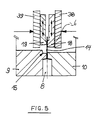
- the example according to FIG. 5 differs differs from that according to FIG. 2 in that the jaws 18 and 19, which pinch the legs 14 between them, are not pivotally mounted, but can be moved lengthways, namely slidable in the longitudinal direction of the legs in another pair of jaws 38 and 39 are stored, which the jaws 18 and 19 between clamp yourself in.
- the outer jaws 38 and 39 are in turn at right angles to the level of the legs 14 slidable. Are they going in that direction Stamp 10 moved towards stamp 9, then the pinched legs 14 pull the cheeks 18 and 19 due to the continued clamping Slightly out of the cheeks 38 and 39 until the legs 14 are pressed into the recess 15. So that the jaws 18 and 19 have little friction in experience the jaws 38 and 39, for example be slidably mounted on needles.
Landscapes
- Engineering & Computer Science (AREA)
- Manufacturing & Machinery (AREA)
- Microelectronics & Electronic Packaging (AREA)
- Lead Frames For Integrated Circuits (AREA)
- Wire Processing (AREA)
- Bending Of Plates, Rods, And Pipes (AREA)
Description
- Figur 1
- zeigt einen Teilschnitt durch eine erfindungsgemässe Vorrichtung, wobei die Schnittebene senkrecht zur gemeinsamen Ebene der Beinchen gelegt ist,
- Figur 2
- zeigt als Detail Z aus der Darstellung gemäss Figur 1 den Kernbereich der Vorrichtung mit Klemmwerkzeug und Einrichtung zur Aufnahme des IC-Gehäuses und mit vorgeletem IC, vor dem Biegen der Beinchen,
- Figur 3
- zeigt in einer Darstellung wie in Figur 2 die Werkzeuganordnung während des Biegevorgangs,
- Figur 4
- zeigt in einer Darstellung entsprechend Figur 2 die Werkzeuganordnung bei vollendetem Biegevorgang, und
- Figur 5
- zeigt schematisch in einer Ansicht entsprechend der Figur 2 eine Werkzeuganordnung mit einem abgewandelten Klemmwerkzeug.
Claims (20)
- Verfahren zum Formen der Anschlußbeinchen von integrierten Schaltkreisen mit einem Gehäuse (8), aus welchem in einer gemeinsamen Ebene (21) liegende Beinchen (14) herausragen, durch Festlegen des Gehäuses (8) und Biegen der Beinchen (14) bei dem die Beinchen (14) von einer Einrichtung (9, 10) zum Festlegen des Gehäuses und in einigem Abstand von diesem Gehäuse von zwei Backen (18, 19) eines Klemmwerkzeugs eingeklemmt werden, wobei dann die Enden der Beinchen (14) unter Aufrechterhaltung der Klemmung in Längsrichtung entlang einem bogenförmigen Weg, welcher in einer die jeweiligen Beinchen (14) enthaltenden, rechtwinkelig zu der gemeinsamen Ebene (21) verlaufende Ebene liegt, zwangsgeführt werden, indem die Backen (18, 19) des Klemmwerkzeugs unter Aufrechterhaltung der Klemmung in Längsrichtung der Beinchen (14) quer zu der gemeinsamen Ebene (21) verschoben werden, und wobei die Beinchen (14) zwischen einer Biegefläche (26) eines der Backen (18) und einer komplementar hier zu gestalteten und schräg gegenüberliegende Gegenform (15) der Einrichtung (9, 10) eingeklemmt werden.
- Verfahren nach Anspruch 1, dadurch gekennzeichnet, daß die Ausrichtung der Enden der Beinchen (14) i.w. erhalten bleibt, während sie auf dem bogenförmigen Weg geführt werden.
- Verfahren nach Anspruch 1 oder 2, dadurch gekennzeichnet, daß die zu einer Seite aus dem Gehäuse herausragenden, zueinander parallelen Beinchen (14) gemeinsam ergriffen und gemeinsam gebogen werden, daß aber die von unterschiedlichen Seiten des Gehäuses herausragenden Gruppen von Beinchen (14) unabhängig voneinander ergriffen und gebogen werden.
- Verfahren nach einem der vorstehenden Ansprüche, dadurch gekennzeichnet, daß die Beinchen (14) unmittelbar neben dem Gehäuse (8) ergriffen und geklemmt werden und dadurch das Gehäuse festgelegt wird.
- Verfahren nach einem der vorstehenden Ansprüche, dadurch gekennzeichnet, daß die Beinchen (14) nahe bei ihren freien Enden eingeklemmt und dann gebogen werden.
- Vorrichtung zum Formen der Anschlußbeinchen (14) von integrierten Schaltkreisen mit einem Gehäuse, aus welchem in einer gemeinsamen Ebene (21) liegende Beinchen (14) herausragen, mit einer Einrichtung (9, 10) zum Festlegen des jeweiligen Gehäuses, neben der Einrichtung (9, 10) zum Festlegen des Gehäuses sind zwei Backen (18, 19) eines Klemmwerkzeugs zum Festklemmen von Beinchen (14) angeordnet, wobei einer der Backen (18) an die Klemmfläche in Richtung gegen die Einrichtung (9, 10) zum Festlegen des Gehäuses anschließend eine Biegefläche (26) hat, an welche sich die Beinchen (14) beim Biegen anlegen, so daß diese Biegefläche (26) die Gestalt der gebogenen Beinchen (14) bestimmt, wobei die Einrichtung (9, 10) eine komplementär zu dieser Biegefläche (26) gestaltete und schräg gegenüberliegende Gegenform (15) aufweist, wobei die Backen (18, 19) um Achsen (20, 24) schwenkbar sind, die parallel zu der gemeinsamen Ebene (21) und rechtwinklig zur Längserstreckung der Beinchen (14) verlaufen, und wobei die Achsen (20, 24) unter Aufrechterhaltung der Klemmung quer zu der gemeinsamen Ebene (21) verschiebbar gelagert sind.
- Vorrichtung zum Formen der Anschlußbeinchen (14) von integrierten Schaltkreisen mit einem Gehäuse, von welchem in einer gemeinsamen Ebene (21) liegende Beinchen (14) herausragen, mit einer Einrichtung (9, 10) zum Festlegen des jeweiligen Gehäuses, neben der Einrichtung (9, 10) zum Festlegen des Gehäuses sind zwei Backen (18, 19) eines Klemmwerkzeugs zum Festklemmen von Beinchen (14) angeordnet, wobei einer der Backen (18) an die Klemmfläche in Richtung gegen die Einrichtung (9, 10) zum Festlegen des Gehäuses anschließend eine Biegefläche (26) hat, an welche sich die Beinchen (14) beim Biegen anlegen, so daß diese Biegefläche (26) die Gestalt der gebogenen Beinchen (14) bestimmt, wobei die Einrichtung (9, 10) eine komplementär zu dieser Biegefläche (26) gestaltete und schräg gegenüberliegende Gegenform (15) aufweist, und wobei die Backen (18, 19) unter Aufrechterhaltung der Klemmung in Längsrichtung der Beinchen (14) sowie quer zu der gemeinsamen Ebene (21) verschiebbar gelagert sind.
- Vorrichtung nach Anspruch 7, dadurch gekennzeichnet, daß die Backen (18, 19) zwischen zwei quer zu der gemeinsamen Ebene (21) verschiebbaren äußeren Backen (38, 39) eingespannt in Längsrichtung der Beinchen (14) verschiebbar gelagert sind.
- Vorrichtung nach Anspruch 6, 7 oder 8, dadurch gekennzeichnet, daß die Biegefläche (26) konvex gerundet ist.
- Vorrichtung nach einem der Ansprüche 6 bis 9, dadurch gekennzeichnet, daß die Einrichtung (9, 10) zum Festlegen des Gehäuses zwei gegeneinander arbeitende Aufnahmen (9, 10) zur Anlage an der Oberseite und der Unterseite des Gehäuses hat.
- Vorrichtung nach einem der Ansprüche 6 bis 10, dadurch gekennzeichnet, daß die Backen (18, 19) relativ zu der Einrichtung (9, 10) so angeordnet sind, dass sie die Beinchen (14) in einigem Abstand vom Gehäuse (8) festklemmen, vorzugsweise nahe bei ihren freien Enden.
- Vorrichtung nach einem der Ansprüche 10 und 11, dadurch gekennzeichnet, dass die Aufnahmen (9, 10) Vorsprünge (12, 13) haben, die an den Gehäuserändern vorbeigreifen, um die Beinchen (14) am Rand des Gehäuses (8) zu ergreifen und zu klemmen.
- Vorrichtung nach Anspruch 6, dadurch gekennzeichnet, daß der eine Backen (18) in Längsrichtung im Führungsgehäuse (2) verschiebbar ist und der andere Backen (19) zurückfedernd gelagert ist.
- Vorrichtung nach Anspruch 13, dadurch gekennzeichnet, daß der mit der Biegefläche (26) ausgestattete Backen (18) durch eine Betätigungseinrichtung (31) vorschiebbar ist.
- Vorrichtung nach Anspruch 6, dadurch gekennzeichnet, daß für den mit der Biegefläche (26) ausgestatteten Backen (18) zusätzlich ein Schwenkantrieb (29, 30, 31) für eine gegen die Einrichtung (9, 10) zur Aufnahme des Gehäuses (8) gerichtete Schweakbewegung vorgesehen ist.
- Verrichtung nach Anspruch 15, dadurch gekennzeichnet, daß der Schwenkantrieb (29, 30, 31) abgefedert (30) ist.
- Vorrichtung nach einem der Ansprüche 6, 13 bis 16, dadurch gekennzeichnet, daß den Backen (18, 19) Rückstellfedern (32, 33) zugeordnet sind.
- Vorrichtung nach einem der Ansprüche 6 bis 17, dadurch gekennzeichnet, daß für die Gruppe der aus einer gemeinsamen Seite des Gehäuses herausragenden Beinchen (14) jeweils ein gemeinsames Paar von Backen (18, 19) vorgesehen ist.
- Vorrichtung nach Anspruch 18, dadurch gekennzeichnet, dass die Paare von Backen (18, 19) unabhängig betätigbar sind.
- Vorrichtung nach einem der Ansprüche 6 und 13-17, dadurch gekennzeichnet, daß die Einrichtung (9, 10) zum Festlegen des Gehäuses gegeneinander arbeitende Aufnahmen (9, 10) zur Anlage an der Oberseite und der Unterseite des Gehäuses hat, und die auf derselben Seite der Ebene (21) der Beinchen (14) liegenden Backen (18) gemeinsam mit dem auf derselben Seite liegenden Aufnahme (10) in einem gemeinsamen Gehäuse (2) geführt sind.
Applications Claiming Priority (3)
| Application Number | Priority Date | Filing Date | Title |
|---|---|---|---|
| DE4234697 | 1992-10-14 | ||
| DE4234697 | 1992-10-14 | ||
| PCT/EP1993/002819 WO1994009510A1 (de) | 1992-10-14 | 1993-10-13 | Verfahren und vorrichtung zum formen der anschlussbeinchen von integrierten schaltkreisen |
Publications (2)
| Publication Number | Publication Date |
|---|---|
| EP0664923A1 EP0664923A1 (de) | 1995-08-02 |
| EP0664923B1 true EP0664923B1 (de) | 2001-06-06 |
Family
ID=6470481
Family Applications (1)
| Application Number | Title | Priority Date | Filing Date |
|---|---|---|---|
| EP93924036A Expired - Lifetime EP0664923B1 (de) | 1992-10-14 | 1993-10-13 | Verfahren und vorrichtung zum formen der anschlussbeinchen von integrierten schaltkreisen |
Country Status (8)
| Country | Link |
|---|---|
| US (1) | US5715872A (de) |
| EP (1) | EP0664923B1 (de) |
| JP (1) | JPH08509574A (de) |
| KR (1) | KR100285158B1 (de) |
| DE (2) | DE59310173D1 (de) |
| MY (1) | MY115135A (de) |
| SG (1) | SG48925A1 (de) |
| WO (1) | WO1994009510A1 (de) |
Families Citing this family (3)
| Publication number | Priority date | Publication date | Assignee | Title |
|---|---|---|---|---|
| DE59310173D1 (de) * | 1992-10-14 | 2001-07-12 | Micron Technology Inc | Verfahren und vorrichtung zum formen der anschlussbeinchen von integrierten schaltkreisen |
| FR2729007B1 (fr) * | 1994-12-29 | 1997-01-24 | Bull Sa | Dispositif de cambrage de pattes conductrices d'un support intermediaire de circuit integre |
| DE19625228C2 (de) * | 1996-06-24 | 1998-05-14 | Siemens Ag | Systemträger für die Montage einer integrierten Schaltung in einem Spritzgußgehäuse |
Family Cites Families (6)
| Publication number | Priority date | Publication date | Assignee | Title |
|---|---|---|---|---|
| JPS6195560A (ja) * | 1984-10-17 | 1986-05-14 | Hitachi Ltd | リ−ド成形方法 |
| JPH0828455B2 (ja) * | 1988-02-24 | 1996-03-21 | 富士通株式会社 | リードフレーム及びそれを用いた電子部品の製造方法 |
| JPH01309725A (ja) * | 1988-06-06 | 1989-12-14 | Teijin Seiki Co Ltd | 電子回路用部品のリード曲げ装置 |
| JPH0795576B2 (ja) * | 1990-02-22 | 1995-10-11 | 株式会社石井工作研究所 | 電子部品のリードの曲げ加工方法及びその曲げ型 |
| US5210936A (en) * | 1992-01-06 | 1993-05-18 | Microelectronics And Computer Technology Corporation | Method and apparatus for the excise and lead form of TAB devices |
| DE59310173D1 (de) * | 1992-10-14 | 2001-07-12 | Micron Technology Inc | Verfahren und vorrichtung zum formen der anschlussbeinchen von integrierten schaltkreisen |
-
1993
- 1993-10-13 DE DE59310173T patent/DE59310173D1/de not_active Expired - Fee Related
- 1993-10-13 US US08/416,888 patent/US5715872A/en not_active Expired - Lifetime
- 1993-10-13 WO PCT/EP1993/002819 patent/WO1994009510A1/de not_active Ceased
- 1993-10-13 KR KR1019950701449A patent/KR100285158B1/ko not_active Expired - Fee Related
- 1993-10-13 SG SG1996003808A patent/SG48925A1/en unknown
- 1993-10-13 JP JP6509622A patent/JPH08509574A/ja active Pending
- 1993-10-13 DE DE4334861A patent/DE4334861A1/de not_active Withdrawn
- 1993-10-13 EP EP93924036A patent/EP0664923B1/de not_active Expired - Lifetime
- 1993-10-14 MY MYPI93002113A patent/MY115135A/en unknown
Also Published As
| Publication number | Publication date |
|---|---|
| SG48925A1 (en) | 1998-05-18 |
| EP0664923A1 (de) | 1995-08-02 |
| KR100285158B1 (ko) | 2001-04-02 |
| DE59310173D1 (de) | 2001-07-12 |
| JPH08509574A (ja) | 1996-10-08 |
| WO1994009510A1 (de) | 1994-04-28 |
| MY115135A (en) | 2003-04-30 |
| KR950703792A (ko) | 1995-09-20 |
| US5715872A (en) | 1998-02-10 |
| DE4334861A1 (de) | 1994-04-21 |
Similar Documents
| Publication | Publication Date | Title |
|---|---|---|
| EP3180138B1 (de) | Biegewerkzeug und greifvorrichtung zum manipulieren des biegewerkzeuges | |
| DE202011004528U1 (de) | Handhabungsvorrichtung zur Handhabung von Gegenständen | |
| DE2427896A1 (de) | Verfahren und vorrichtung zum einbauen von stiften od. dgl. in leiterplatten od. dgl | |
| EP0965413B1 (de) | Anlage für die Durchführung einer Folge aus mehreren Montage- und/oder Bearbeitungsvorgängen an Werkstücken, insbesondere Kleinteilen | |
| DE1955193B2 (de) | Halter zum Einsetzen und Entnehmen eines Werkzeuges in eine bzw. aus einer Maschine | |
| EP2481492B1 (de) | Biegewerkzeug für das Freiformbiegen von Blechen | |
| DE2056523B2 (de) | Verfahren und Vorrichtung zum Anbringen von oberen Endstücken an Schließketten von Reißverschlüssen | |
| DE69510388T2 (de) | Vorrichtung für die automatische Befestigung von selbststanzenden Muttern | |
| DE2360947B2 (de) | Vorrichtung zum Ausrichten einer Gruppe von Kuppelgliedern einer ReißverschluBkette | |
| DE3941551A1 (de) | Vorrichtung zum positionieren von plattenfoermigen werkstuecken | |
| DE8311424U1 (de) | Vorrichtung zum einsetzen von stiften mit viereckigem querschnitt in die leiterplatte einer gedruckten schaltung | |
| DE10039525A1 (de) | Werkzeugmaschine mit Greifer und oder Werkzeugmagazinsystem | |
| EP0188776A2 (de) | Transfereinrichtung zum schrittweisen Material- und/oder Werkstücktransport, insbesondere in Pressen | |
| DE4334861A1 (de) | Verfahren und Vorrichtung zum Formen der Anschlußbeinchen von integrierten Schaltkreisen | |
| DE3104667A1 (de) | Ladeeinrichtung fuer metallrohlinge | |
| DE2152784A1 (de) | Vorrichtung und Verfahren zum Einsetzen von Einpreßmuttern in ein Werkstück | |
| DE102019104836A1 (de) | Spannvorrichtung für eine Werkzeugmaschine, insbesondere ein Bearbeitungszentrum | |
| DE2435395A1 (de) | Transportmechanismus fuer eine quertransportpresse | |
| DE8610436U1 (de) | Einrichtung zum Fördern von langgestreckten Abschnitten und Abschnitthalter | |
| DE2814334B2 (de) | Verfahren zum Montieren eines Steckverbinders auf einer gedruckten Schaltung sowie Werkzeug und Steckverbinder zur Durchführung des Verfahrens | |
| DE4416843A1 (de) | Zick-Zack-Vorschubeinrichtung | |
| DE102019007019B4 (de) | Montagevorrichtung | |
| DE2625738A1 (de) | Automatische einrichtung zum bestuecken von leiterplatten | |
| EP0139229A2 (de) | Beschaltwerkzeug zur Verdrahtung von elektrischen, mehrpoligen Steckverbindern, Steckleitungen o. dgl. in Klemmschneidtechnik | |
| DE2719066C3 (de) | Nockeneinrichtung |
Legal Events
| Date | Code | Title | Description |
|---|---|---|---|
| PUAI | Public reference made under article 153(3) epc to a published international application that has entered the european phase |
Free format text: ORIGINAL CODE: 0009012 |
|
| 17P | Request for examination filed |
Effective date: 19950515 |
|
| AK | Designated contracting states |
Kind code of ref document: A1 Designated state(s): DE FR GB NL |
|
| R17P | Request for examination filed (corrected) |
Effective date: 19950515 |
|
| 17Q | First examination report despatched |
Effective date: 19970414 |
|
| GRAG | Despatch of communication of intention to grant |
Free format text: ORIGINAL CODE: EPIDOS AGRA |
|
| GRAG | Despatch of communication of intention to grant |
Free format text: ORIGINAL CODE: EPIDOS AGRA |
|
| GRAH | Despatch of communication of intention to grant a patent |
Free format text: ORIGINAL CODE: EPIDOS IGRA |
|
| GRAH | Despatch of communication of intention to grant a patent |
Free format text: ORIGINAL CODE: EPIDOS IGRA |
|
| GRAH | Despatch of communication of intention to grant a patent |
Free format text: ORIGINAL CODE: EPIDOS IGRA |
|
| GRAA | (expected) grant |
Free format text: ORIGINAL CODE: 0009210 |
|
| AK | Designated contracting states |
Kind code of ref document: B1 Designated state(s): DE FR GB NL |
|
| PG25 | Lapsed in a contracting state [announced via postgrant information from national office to epo] |
Ref country code: NL Free format text: LAPSE BECAUSE OF FAILURE TO SUBMIT A TRANSLATION OF THE DESCRIPTION OR TO PAY THE FEE WITHIN THE PRESCRIBED TIME-LIMIT Effective date: 20010606 Ref country code: FR Free format text: LAPSE BECAUSE OF FAILURE TO SUBMIT A TRANSLATION OF THE DESCRIPTION OR TO PAY THE FEE WITHIN THE PRESCRIBED TIME-LIMIT Effective date: 20010606 |
|
| REF | Corresponds to: |
Ref document number: 59310173 Country of ref document: DE Date of ref document: 20010712 |
|
| GBT | Gb: translation of ep patent filed (gb section 77(6)(a)/1977) |
Effective date: 20010904 |
|
| PGFP | Annual fee paid to national office [announced via postgrant information from national office to epo] |
Ref country code: FR Payment date: 20011010 Year of fee payment: 9 |
|
| NLV1 | Nl: lapsed or annulled due to failure to fulfill the requirements of art. 29p and 29m of the patents act | ||
| EN | Fr: translation not filed | ||
| REG | Reference to a national code |
Ref country code: GB Ref legal event code: IF02 |
|
| PLBE | No opposition filed within time limit |
Free format text: ORIGINAL CODE: 0009261 |
|
| STAA | Information on the status of an ep patent application or granted ep patent |
Free format text: STATUS: NO OPPOSITION FILED WITHIN TIME LIMIT |
|
| 26N | No opposition filed | ||
| PGFP | Annual fee paid to national office [announced via postgrant information from national office to epo] |
Ref country code: DE Payment date: 20081014 Year of fee payment: 16 |
|
| PG25 | Lapsed in a contracting state [announced via postgrant information from national office to epo] |
Ref country code: DE Free format text: LAPSE BECAUSE OF NON-PAYMENT OF DUE FEES Effective date: 20100501 |
|
| PGFP | Annual fee paid to national office [announced via postgrant information from national office to epo] |
Ref country code: GB Payment date: 20101013 Year of fee payment: 18 |
|
| GBPC | Gb: european patent ceased through non-payment of renewal fee |
Effective date: 20111013 |
|
| PG25 | Lapsed in a contracting state [announced via postgrant information from national office to epo] |
Ref country code: GB Free format text: LAPSE BECAUSE OF NON-PAYMENT OF DUE FEES Effective date: 20111013 |