EP0665099A2 - Procédé et dispositif pour la fabrication d'un laminat et objets produits de ces laminats - Google Patents
Procédé et dispositif pour la fabrication d'un laminat et objets produits de ces laminats Download PDFInfo
- Publication number
- EP0665099A2 EP0665099A2 EP94115114A EP94115114A EP0665099A2 EP 0665099 A2 EP0665099 A2 EP 0665099A2 EP 94115114 A EP94115114 A EP 94115114A EP 94115114 A EP94115114 A EP 94115114A EP 0665099 A2 EP0665099 A2 EP 0665099A2
- Authority
- EP
- European Patent Office
- Prior art keywords
- conveyor
- plate
- cutting
- station
- laminate
- Prior art date
- Legal status (The legal status is an assumption and is not a legal conclusion. Google has not performed a legal analysis and makes no representation as to the accuracy of the status listed.)
- Withdrawn
Links
Images

Classifications
-
- B—PERFORMING OPERATIONS; TRANSPORTING
- B32—LAYERED PRODUCTS
- B32B—LAYERED PRODUCTS, i.e. PRODUCTS BUILT-UP OF STRATA OF FLAT OR NON-FLAT, e.g. CELLULAR OR HONEYCOMB, FORM
- B32B29/00—Layered products comprising a layer of paper or cardboard
- B32B29/002—Layered products comprising a layer of paper or cardboard as the main or only constituent of a layer, which is next to another layer of the same or of a different material
- B32B29/005—Layered products comprising a layer of paper or cardboard as the main or only constituent of a layer, which is next to another layer of the same or of a different material next to another layer of paper or cardboard layer
-
- B—PERFORMING OPERATIONS; TRANSPORTING
- B32—LAYERED PRODUCTS
- B32B—LAYERED PRODUCTS, i.e. PRODUCTS BUILT-UP OF STRATA OF FLAT OR NON-FLAT, e.g. CELLULAR OR HONEYCOMB, FORM
- B32B29/00—Layered products comprising a layer of paper or cardboard
-
- B—PERFORMING OPERATIONS; TRANSPORTING
- B32—LAYERED PRODUCTS
- B32B—LAYERED PRODUCTS, i.e. PRODUCTS BUILT-UP OF STRATA OF FLAT OR NON-FLAT, e.g. CELLULAR OR HONEYCOMB, FORM
- B32B37/00—Methods or apparatus for laminating, e.g. by curing or by ultrasonic bonding
- B32B37/12—Methods or apparatus for laminating, e.g. by curing or by ultrasonic bonding characterised by using adhesives
- B32B37/1284—Application of adhesive
-
- B—PERFORMING OPERATIONS; TRANSPORTING
- B32—LAYERED PRODUCTS
- B32B—LAYERED PRODUCTS, i.e. PRODUCTS BUILT-UP OF STRATA OF FLAT OR NON-FLAT, e.g. CELLULAR OR HONEYCOMB, FORM
- B32B39/00—Layout of apparatus or plants, e.g. modular laminating systems
-
- B—PERFORMING OPERATIONS; TRANSPORTING
- B32—LAYERED PRODUCTS
- B32B—LAYERED PRODUCTS, i.e. PRODUCTS BUILT-UP OF STRATA OF FLAT OR NON-FLAT, e.g. CELLULAR OR HONEYCOMB, FORM
- B32B7/00—Layered products characterised by the relation between layers; Layered products characterised by the relative orientation of features between layers, or by the relative values of a measurable parameter between layers, i.e. products comprising layers having different physical, chemical or physicochemical properties; Layered products characterised by the interconnection of layers
- B32B7/04—Interconnection of layers
- B32B7/12—Interconnection of layers using interposed adhesives or interposed materials with bonding properties
-
- B—PERFORMING OPERATIONS; TRANSPORTING
- B32—LAYERED PRODUCTS
- B32B—LAYERED PRODUCTS, i.e. PRODUCTS BUILT-UP OF STRATA OF FLAT OR NON-FLAT, e.g. CELLULAR OR HONEYCOMB, FORM
- B32B2305/00—Condition, form or state of the layers or laminate
- B32B2305/70—Scrap or recycled material
-
- B—PERFORMING OPERATIONS; TRANSPORTING
- B32—LAYERED PRODUCTS
- B32B—LAYERED PRODUCTS, i.e. PRODUCTS BUILT-UP OF STRATA OF FLAT OR NON-FLAT, e.g. CELLULAR OR HONEYCOMB, FORM
- B32B2317/00—Animal or vegetable based
- B32B2317/12—Paper, e.g. cardboard
-
- B—PERFORMING OPERATIONS; TRANSPORTING
- B32—LAYERED PRODUCTS
- B32B—LAYERED PRODUCTS, i.e. PRODUCTS BUILT-UP OF STRATA OF FLAT OR NON-FLAT, e.g. CELLULAR OR HONEYCOMB, FORM
- B32B2479/00—Furniture
Definitions
- the invention relates to a process for the production of laminate panels, which is formed from superimposed and glued (glued) recycled paper layers, and to a device for carrying out the process and to the laminate molded part produced, in particular for furniture parts.
- the object of the invention is to enable a novel process for the production of laminate mold plates in a simple, rational and inexpensive layering of the recycled paper and glue with good dimensional stability and short curing time as well as immediate or later, final shaping and finishing.
- Another task is seen in a rationally operating device with automatically interacting production and processing stations with direct or interrupted passage of the laminate panels.
- Another task lies in the special structure of the laminate panels and the laminate molded parts made from them and their use in the furniture industry as light, stable and inexpensive furniture parts with any shapes and sizes.
- the procedural task is solved by the characterizing features of claim 1, the device task by the features of claim 8 and the molding task by the features of claims 20 and 21.
- the invention has created a method and a device (system) which operates according to it, with which laminate panels are produced simply, efficiently and with a short curing time and then formatted to the desired size in a direct or interrupted pass, then brought into the desired shape and then machined can be.
- the entire device including several processing stations enables a rational and optimal manufacturing, further shaping and finishing process; the molded part can be produced in various sizes and shapes and, due to its structure, its choice of material and adhesive and its deformability, has a light and stable structure and an inexpensive design and is versatile, particularly in the furniture industry.
- (1) denotes a laminate board, which is formed from layers of paper (2), preferably layers of recycled paper, lying one above the other and connected to one another by adhesive (glue) (3).
- Fig. 1 shows the laminate board (1) in the flat manufacturing version and Fig. 2 shows a molded part (1A) made from the laminate board (1); this molded part (1A) can have a wide variety of shapes.
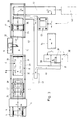
- the plate laying station (6) has a laying table (17) which can be moved back and forth on linear guides in a base frame (16).
- the base frame (16) receives an exchangeable paper roll (4) with associated, driven pull-off rollers (18) and tension compensation rollers (19).
- a pressure roller (20) is arranged above it and a pressure compensation roller (21) is arranged in the feed area (VA) of the laying table (17).
- a driven cutting knife (22) is arranged above it in the laying table feed direction (VL) behind the press roller (20) and glue application nozzles (23) are provided behind it.
- the plate conveyor (7) connected downstream of the plate laying station (6) for conveying each laminate plate (1) to the plate transfer station (8) completed in the plate laying station (6) has a linearly movable, driven trolley (27) with vacuum suction cups (27) in a base frame (26). 28).
- the plate transfer station (8) connected downstream of the plate conveyor (7) has in a base frame (29) a driven roller conveyor (30) with an integrated lifting and lowering conveyor rollers (31) which can be operated transversely to the roller conveyor (30).
- the water jet cutting station (9) arranged between the plate transfer station (8) and the cutting conveyor (11) has cutting heads (33) that can be moved on a base frame (32) on XY axes above the cutting and transport table (10) and contains a high-pressure water treatment system; the cutting and transport table (10) has in a base frame support and transport means such as rollers, chains, interchangeable support mounts for the plates to be cut (1) and a water collecting container for the cutting water.
- the cutting conveyor (11) has on a base frame (34) a longitudinally and transversely movable, driven trolley (35) with vacuum suction devices (36) for receiving the cut plates (1) from the cutting and transport table (10) and for transporting the plates (1) to the conveyor (12) which is formed in a straight extension or at an angle to the cutting conveyor (11) and is formed by a driven, clocked accumulation conveyor roller conveyor.
- the cutting and transport table (10) projects into the blank conveyor (11) so that the plates (1) conveyed therein can be picked up by the trolley (35) with its suction cups (36).
- the contour and molding press (13) is formed by a hydraulic multi-column stand press with heatable tool carrier plates and molds made of thermally conductive material that can be interchangeably fixed thereon.
- the conveyor (14) arranged between the contour and molding press (13) and the processing station (15) is formed by a driven, clocked accumulation conveyor roller conveyor.
- the processing station (15) has in a machine frame (37) a sliding table (38) which can be moved alternately in two molded part loading positions, with molded part clamping elements and tools (39), such as milling cutters, drills, which can be moved on XY axes and pivoted about a third axis. Grinding wheels or the like.
- a waste transport (40) is guided from the cutting and transport table (10) and from the processing station (15) to a waste collecting container (41).
- heating station such as a heat tunnel
- the manufacturing process is as follows: the recycling paper roll (4) is inserted with a forklift into an axleless unwinding device of the plate laying station (6). For the first time, the beginning of the paper is pulled manually through the roller sets (19, 18) and inserted into the paper clip (43) of the laying table (17). The laying table (17) assumes the starting position (VA) according to FIG. 4.
- the unwinding and pulling of the paper web (5) from the roller (4) takes place as a function of the driving speed of the laying table (17).
- the laying table (17) travels in the forward direction (VL) - on a linear travel path - and the first paper layer (2) is placed, which is then cut off from the web (5) at the leading end by the cross-movable cutting knife (22) and by the integrated Vacuum suction cup (24) is held.
- the laying table (17) then moves back in the direction of the arrow (VR) and into the starting position (VA) according to FIG. 4.
- the table (17) moves forward in cycles, the layer (2) is laid, the table (17) stops, the layer (2) is cut off and the table (17) moves back.
- the next beginning of the paper is automatically drawn into the paper clip (43) via the paper guide plate (25) and the next laying process can begin, while simultaneously gluing (3) the spray nozzle (23) onto the lower layer (2) before joining the paper is sprayed on.
- the laminate board (1) As soon as the laminate board (1) has been produced in accordance with the specified program - the desired number of layers - it is automatically removed from the laying table (17) by the board conveyor (7).
- the laying table (17) returns to the starting position (VA) and the next automatic plate production is started.
- the finished laminate plate (1) is removed from the laying table (17) and transported by the trolley (27) in the longitudinal direction to the plate transfer (8) and placed on the same.
- the plate conveyor (7) returns to the ready position for receiving the next laminate plate (1).
- the plate transfer (8) serves as a buffer space and as a feed unit to the cutting and transport table (10) for the immediate further processing of the laminate plate (1).
- the laminate panels (1) can also be removed laterally in the direction of the arrow (B) by the lifting and lowering conveyor rollers (31) from the panel transfer (8) and fed to an intermediate storage facility.
- the laminate plate (1) fed to the cutting and transport table (10) with the plate transfer (8) is taken over by exchangeable receptacles of the table (10) in synchronism and automatically transported to the cutting position.
- the previously produced blanks are simultaneously transported into the transfer position of the blank conveyor (11).
- the cut waste is automatically brought onto a waste disposal belt of the waste transporter (40) when the transport table (10) moves up.
- the water jet cutter (9) is started automatically.
- the two cutting heads (33) work synchronously on each half of the plate and thus create the cuts according to the specified dimensions.
- the cutting water is collected in the water collecting tank and discharged via an overflow.
- the cutting conveyor (11) for the transport of the cut plates (1) from the transport table (10) to the conveyor (12) travels with its trolley (35) on the XY linear axes to the cut plate parts, the vacuum cups (36) lower and do the cutting.
- the blanks are stacked on the conveyor (12).
- the stacks formed with the blank conveyor (11) are removed with the accumulation roller conveyor (12) as soon as the predetermined stack height has been reached.
- the stacks are automatically transported to the end of the conveyor (12) and can be removed here by the operator of the hydraulic press (13).
- the operator inserts the first blank and feeds the press (13) with the two-hand control.
- the press (13) opens automatically. The operator removes the molded part (1A) and brings it onto the conveyor (14) for transport to the processing station (15).
- the molded parts (1A) to be machined are brought into the respective free receptacles of the sliding table (38) of the machining station (15) by the operator. By pressing the button, the pneumatic clamps of the receptacles are closed and the part is released for processing.
- the sliding table (38) moves into the processing position and the automatic processing is carried out in accordance with a predetermined program.
- the operator can remove the previously machined part from the second workpiece carrier, place a new part and release the machining.
- the waste transporter (40) also brings the waste, chips or the like accumulating in the processing station (15) to the collecting container (41).
- the tools in the press (13) can be heated, with hardened plate blanks or cooled with previously heated plate blanks.
- Channels for a heating or cooling medium, such as oil, can be provided in the tools and these tools are thermostatically controlled.
- the temporarily stored cured laminate panels (1) are reinserted into the panel transfer (8) in the direction of the arrow (C) and then pass through the same stations (9 to 15), whereby they pass through a warm-up station (42) before being introduced into the press (13).
- a hardener can be introduced into the glue (3) in a preferred manner, the adhesive being mixed with the hardener in the spray jet outside the spray heads (23) and applied together.
- the hardener causes the shape of the laminate board (1) to stabilize more quickly (adhesive crosslinking), as a result of which the drying time is greatly reduced and the board (1) can be processed immediately.
- the adhesive and hardener can be softened for the deformation of the plate (1).
- the adhesive will dissolve even with a short moisture absorption, and the paper layers (2) will fall apart along the adhesive layers (3).
- a laminate board (1) glued with an adhesive with hardener has a significantly longer service life, since the adhesive does not dissolve even with long absorption of moisture and therefore the paper layers do not fall apart, but the paper dissolves even after a long period in the water.
- the laminate plate can be used as a flat plate (1) according to FIG. 1 or as a deformed plate (1A) according to FIG. 2 with a rounded edge (1b), drawn-in shape (1C), contour surface and. Training and the like for furniture parts of all kinds, such as frame parts, back and armrest substructures, table tops, wall and ceiling parts or the like. Use.
Landscapes
- Laminated Bodies (AREA)
Applications Claiming Priority (2)
| Application Number | Priority Date | Filing Date | Title |
|---|---|---|---|
| DE4400885 | 1994-01-14 | ||
| DE4400885A DE4400885A1 (de) | 1994-01-14 | 1994-01-14 | Verfahren und Vorrichtung zur Herstellung von Laminatplatten und danach sowie damit hergestelltes Laminatplatten-Formteil |
Publications (2)
| Publication Number | Publication Date |
|---|---|
| EP0665099A2 true EP0665099A2 (fr) | 1995-08-02 |
| EP0665099A3 EP0665099A3 (fr) | 1996-08-14 |
Family
ID=6507894
Family Applications (1)
| Application Number | Title | Priority Date | Filing Date |
|---|---|---|---|
| EP94115114A Withdrawn EP0665099A3 (fr) | 1994-01-14 | 1994-09-26 | Procédé et dispositif pour la fabrication d'un laminat et objets produits de ces laminats. |
Country Status (2)
| Country | Link |
|---|---|
| EP (1) | EP0665099A3 (fr) |
| DE (1) | DE4400885A1 (fr) |
Cited By (2)
| Publication number | Priority date | Publication date | Assignee | Title |
|---|---|---|---|---|
| DE19544653C1 (de) * | 1995-11-30 | 1997-04-03 | Steinhoff Laminat Gmbh | Materialkreislauffähiges Plattenmaterial und dessen Herstellungsverfahren |
| AT16818U1 (de) * | 2019-07-16 | 2020-09-15 | Wilhelm Huellerbrand | Mehrschichtige Papierbahn |
Families Citing this family (3)
| Publication number | Priority date | Publication date | Assignee | Title |
|---|---|---|---|---|
| DE102008024155A1 (de) * | 2008-02-28 | 2009-09-03 | Ben Dratz | Verfahren zur Herstellung eines Formkörpers aus Altpapier und/oder Altpappe, Formkörper und Gebäudeteil |
| DE102014107941A1 (de) * | 2014-06-05 | 2015-12-17 | Siggset + Print & Media Ag | Verwendungsverfahren einer Anlage zur Herstellung von Plattenmaterial aus Papier, damit hergestelltes Plattenmaterial sowie Anlage dazu |
| NL2017777B1 (en) * | 2016-11-14 | 2018-05-25 | Newspaperwood B V | An assembly for producing a semi-finished product from newspapers as well as a corresponding method. |
Family Cites Families (6)
| Publication number | Priority date | Publication date | Assignee | Title |
|---|---|---|---|---|
| DE463441C (de) * | 1926-10-29 | 1928-07-28 | Otto Krueger | Verfahren zur Herstellung von aus Pappe gepraegten Rahmen und anderen Reliefdarstellungen |
| US1920109A (en) * | 1932-08-31 | 1933-07-25 | Ruegenberg Gottfriel | Apparatus for producing packing strips |
| US1943145A (en) * | 1932-08-31 | 1934-01-09 | Ruegenberg Gottfried | Method of producing packing strips |
| FR2336246A2 (fr) * | 1975-02-05 | 1977-07-22 | Roth Sa Freres | Procede de fabrication de panneaux en forme a base de carton et de mousse, et panneaux ainsi realises |
| DE2841151C2 (de) * | 1978-09-21 | 1987-04-23 | Nissan Motor Co., Ltd., Yokohama, Kanagawa | Vorrichtung zum Preßverformen einer ebenen Wellpappenplatte |
| JP2620905B2 (ja) * | 1992-06-09 | 1997-06-18 | 王子建材工業株式会社 | ハニカム構造体用積層体の製造方法と製造装置 |
-
1994
- 1994-01-14 DE DE4400885A patent/DE4400885A1/de not_active Withdrawn
- 1994-09-26 EP EP94115114A patent/EP0665099A3/fr not_active Withdrawn
Cited By (3)
| Publication number | Priority date | Publication date | Assignee | Title |
|---|---|---|---|---|
| DE19544653C1 (de) * | 1995-11-30 | 1997-04-03 | Steinhoff Laminat Gmbh | Materialkreislauffähiges Plattenmaterial und dessen Herstellungsverfahren |
| WO1997019814A1 (fr) * | 1995-11-30 | 1997-06-05 | Steinhoff Laminat Gmbh | Stratifie recyclable et son procede de fabrication |
| AT16818U1 (de) * | 2019-07-16 | 2020-09-15 | Wilhelm Huellerbrand | Mehrschichtige Papierbahn |
Also Published As
| Publication number | Publication date |
|---|---|
| DE4400885A1 (de) | 1995-07-20 |
| EP0665099A3 (fr) | 1996-08-14 |
Similar Documents
| Publication | Publication Date | Title |
|---|---|---|
| DE3941277C1 (fr) | ||
| DE69606615T2 (de) | Vorrichtung zum anbringen und beschneiden von kantenmaterial an plattenförmigen werkstücken | |
| EP1990151B1 (fr) | Machine d'usinage | |
| EP0860253A2 (fr) | Procédé et appareil pour la fabrication de portes multi-couches | |
| WO2016087208A1 (fr) | Équipement diviseur de panneaux pour diviser des pièces en forme de panneaux ainsi que son procédé de fonctionnement | |
| EP1810801A1 (fr) | Système de fabrication de pièces en forme de plaques | |
| EP0665099A2 (fr) | Procédé et dispositif pour la fabrication d'un laminat et objets produits de ces laminats | |
| DE102021125391B4 (de) | Entstapelungsvorrichtung und Holzbearbeitungsanlage mit einer derartigen Entstapelungsvorrichtung | |
| DE19627946B4 (de) | Einrichtung zum Herstellen von flächigen Möbelteilen aus großen Platten | |
| EP3713727B1 (fr) | Procédé de traitement de pièces en forme de plaque | |
| DE102004007225B3 (de) | Verfahren und Vorrichtung zum Fügen eines Sandwichplattenleistenrahmens | |
| DE3936947A1 (de) | Anordnung zur beschickung von vorzugsweise einspindeligen nc-leiterplatten-koordinatenbohrmaschinen mit zu bohrenden leiterplatten bzw. zum abtransport fertig gebohrter leiterplatten | |
| DE102020115230B4 (de) | Verfahren zum Verarbeiten plattenförmiger Werkstücke | |
| DE2150021C3 (de) | Anlegevorrichtung | |
| EP3365147A1 (fr) | Procédé permettant d'enturer des feuilles de contreplaqué | |
| EP2529907A2 (fr) | Agencement d'appareils et installation destinés à la préparation de bois composites | |
| DE10335029B4 (de) | Beschick-und Entleervorrichtung für Pressen, insbesondere Einetagenpressen | |
| EP0410362B1 (fr) | Dispositif pour tailler des plaques | |
| DE10152402A1 (de) | Verfahren und Vorrichtung zum Herausarbeiten von kleinteiligen Objekten aus plattenförmigem Ausgangsmaterial | |
| EP2759385B1 (fr) | Procédé pour la fabrication d'un faisceau de placage dans le flux de la fabrication de bois de couche de placage | |
| DE1222659C2 (de) | Verfahren und Vorrichtung zur Herstellung von in einem Arbeitsgang in einer Heisspresse gepressten und mindestens einseitig oberflaechen-beschichteten Pressplatten aus mit waerme-haertendem Bindemittel versetzten Teilchen, wie Holzspaenen, Fasern od. dgl. | |
| DE19938568A1 (de) | Verfahren zum Besäumen von Kanten von Werkstücken, insbesondere von beschichteten Platten sowie Vorrichtungen zur Durchführung solcher Verfahren | |
| EP0648598A2 (fr) | Procédé et dispositif pour la fabrication des produits multicouches et produit multicouche | |
| DE102009053420A1 (de) | Verfahren und Vorrichtung für das Herstellen eines Endprodukts in einer Folding-Technik | |
| DE19650558C2 (de) | Verfahren und Vorrichtung zur Herstellung von Verleimprofilen an Hölzern |
Legal Events
| Date | Code | Title | Description |
|---|---|---|---|
| PUAI | Public reference made under article 153(3) epc to a published international application that has entered the european phase |
Free format text: ORIGINAL CODE: 0009012 |
|
| AK | Designated contracting states |
Kind code of ref document: A2 Designated state(s): AT BE CH DE DK ES FR GB GR IE IT LI LU MC NL PT SE |
|
| PUAL | Search report despatched |
Free format text: ORIGINAL CODE: 0009013 |
|
| AK | Designated contracting states |
Kind code of ref document: A3 Designated state(s): AT BE CH DE DK ES FR GB GR IE IT LI LU MC NL PT SE |
|
| STAA | Information on the status of an ep patent application or granted ep patent |
Free format text: STATUS: THE APPLICATION IS DEEMED TO BE WITHDRAWN |
|
| 18D | Application deemed to be withdrawn |
Effective date: 19970217 |