EP0665444B1 - Détecteur de capacité d'une batterie - Google Patents
Détecteur de capacité d'une batterie Download PDFInfo
- Publication number
- EP0665444B1 EP0665444B1 EP95101249A EP95101249A EP0665444B1 EP 0665444 B1 EP0665444 B1 EP 0665444B1 EP 95101249 A EP95101249 A EP 95101249A EP 95101249 A EP95101249 A EP 95101249A EP 0665444 B1 EP0665444 B1 EP 0665444B1
- Authority
- EP
- European Patent Office
- Prior art keywords
- battery
- voltage
- signal
- communication device
- response
- Prior art date
- Legal status (The legal status is an assumption and is not a legal conclusion. Google has not performed a legal analysis and makes no representation as to the accuracy of the status listed.)
- Expired - Lifetime
Links
- 230000005540 biological transmission Effects 0.000 claims description 50
- 238000004891 communication Methods 0.000 claims description 32
- 230000004044 response Effects 0.000 claims description 25
- 238000001514 detection method Methods 0.000 claims description 13
- 238000000034 method Methods 0.000 claims description 8
- 230000007423 decrease Effects 0.000 claims 2
- 230000005684 electric field Effects 0.000 description 13
- 238000010586 diagram Methods 0.000 description 8
- 230000006870 function Effects 0.000 description 8
- 230000005611 electricity Effects 0.000 description 3
- 230000003213 activating effect Effects 0.000 description 1
- 230000000694 effects Effects 0.000 description 1
- 238000010295 mobile communication Methods 0.000 description 1
- 238000012544 monitoring process Methods 0.000 description 1
Images



Classifications
-
- G—PHYSICS
- G01—MEASURING; TESTING
- G01R—MEASURING ELECTRIC VARIABLES; MEASURING MAGNETIC VARIABLES
- G01R19/00—Arrangements for measuring currents or voltages or for indicating presence or sign thereof
- G01R19/165—Indicating that current or voltage is either above or below a predetermined value or within or outside a predetermined range of values
- G01R19/16533—Indicating that current or voltage is either above or below a predetermined value or within or outside a predetermined range of values characterised by the application
- G01R19/16538—Indicating that current or voltage is either above or below a predetermined value or within or outside a predetermined range of values characterised by the application in AC or DC supplies
- G01R19/16542—Indicating that current or voltage is either above or below a predetermined value or within or outside a predetermined range of values characterised by the application in AC or DC supplies for batteries
-
- G—PHYSICS
- G01—MEASURING; TESTING
- G01R—MEASURING ELECTRIC VARIABLES; MEASURING MAGNETIC VARIABLES
- G01R31/00—Arrangements for testing electric properties; Arrangements for locating electric faults; Arrangements for electrical testing characterised by what is being tested not provided for elsewhere
- G01R31/36—Arrangements for testing, measuring or monitoring the electrical condition of accumulators or electric batteries, e.g. capacity or state of charge [SoC]
- G01R31/3644—Constructional arrangements
- G01R31/3648—Constructional arrangements comprising digital calculation means, e.g. for performing an algorithm
-
- G—PHYSICS
- G01—MEASURING; TESTING
- G01R—MEASURING ELECTRIC VARIABLES; MEASURING MAGNETIC VARIABLES
- G01R15/00—Details of measuring arrangements of the types provided for in groups G01R17/00 - G01R29/00, G01R33/00 - G01R33/26 or G01R35/00
- G01R15/04—Voltage dividers
-
- G—PHYSICS
- G01—MEASURING; TESTING
- G01R—MEASURING ELECTRIC VARIABLES; MEASURING MAGNETIC VARIABLES
- G01R31/00—Arrangements for testing electric properties; Arrangements for locating electric faults; Arrangements for electrical testing characterised by what is being tested not provided for elsewhere
- G01R31/36—Arrangements for testing, measuring or monitoring the electrical condition of accumulators or electric batteries, e.g. capacity or state of charge [SoC]
- G01R31/3644—Constructional arrangements
- G01R31/3646—Constructional arrangements for indicating electrical conditions or variables, e.g. visual or audible indicators
Definitions
- the present invention relates to a communication device comprising a battery capacity detector, and more particularly to a device for accurately detecting a capacity drop in the power supply batteries used for communication equipment.
- a portable equipment for mobile communication such as a portable telephone
- batteries are generally used for its power supply. Therefore, the normal operation of the equipment cannot be secured if the battery power is deteriorated. For that reason, there have been proposed devices which urge the user the replacement or recharging of the batteries by issuing an alarm when the battery power, for example, the battery voltage, dropped to below a specified voltage level.
- a cordless telephone system having such an alarm function is disclosed in, for example, Japanese Patent Laid-Open Application No. 354230/1992 (JP-A-H04-354230).
- This cordless telephone system includes a master set and a slave set which is carried for use.
- a battery capacity detector detects the voltage of the batteries which supply power to a communication part which includes a radio part, a modem, a control part, and the like.
- the control part displays in a display part a signal that indicates the drop of the remaining capacity, and notifies the information to the master set via a communication part.
- the master set Upon receipt of this signal the master set issues an alarm.
- a radio data transmitter such as a teleterminal, has a function of controlling the voltage of transmission signals in response to the communication circumstances.
- the radio data transmitter has a function of monitoring the electric field intensity of a received radio signal.
- the transmission voltage is increased successively in accordance with the electric field intensity in order to perform all the time a suitable data transmission corresponding to the electric field intensity.
- the detector for detecting the drop of the battery voltage as described in the above is installed in the radio data transmitter, the load in the circuit supplied with the power is increased with the increase in the transmission power, causing a drop in the battery voltage. Because of this, in a type of device which detects the battery capacity based on the battery voltage, a drop in the battery voltage is detected when the transmission power is increased, and an alarm is issued sometimes in spite of the fact that a sufficient battery capacity is remaining.
- the system judges the situation as a drop in the battery capacity, which results in a problem of erroneous display or alarm issuance.
- the battery voltage discriminator circuit for an apparatus having a battery and a plurality of loads which are driven by the battery and operate under various kinds of load conditions is disclosed.
- the circuit When the output voltage of said battery means drops under a predetermined reference voltage, the circuit generates a signal indicative of the voltage drop.
- the circuit has a reference voltage setting circuit for setting the reference voltage to one of predetermined values, which corresponds to the kind of the current load condition, and a reference voltage change circuit for activating the reference voltage setting circuit for a period of time in response to the change in the kind of current load condition.
- EP-A-0 416 589 relates to a computer having a function of detecting a low-battery state.
- a battery is used as a power source for a computer apparatus.
- a reference voltage for determining a low-battery state of the battery is set in consideration of not only the current value of a current output from the battery but also the temperature of the battery. An output voltage from the battery is compared with the reference voltage, thereby determining whether or not the battery is in the low-battery state.
- DE-A-25 11 681 discloses a device for indicating the charge state of a battery with changing loads, in particular, for a transmitter/receiver device. During transmitting the output voltage of the battery is compared with the voltage during the receiving. When the difference between the voltage during receiving and during transmitting is higher than a characteristic value the decharged state of the battery is indicated.
- EP-A-0 512 711 relates to a device for measuring the quantity of electricity stored in a battery of a transceiver comprising a voltage detection circuit for detecting the battery voltage, an A/D converter for converting the detected battery voltage into data, and a calculation circuit for calculating the quantity of battery electricity from the voltage data.
- the A/D converter operates to sample the battery voltage during the period when transmission and receiption are off and thus when the battery voltage does not pulsate, whereby the battery electricity can be evaluated accurately.
- Another object of this invention is to provide a communication device and method capable of detecting accurately the drop in the battery capacity irrespective of the changes in the transmission power of a transmitter.
- a communication device it is desirable to have a function of detecting the battery capacity based on the battery voltage, and of urging the user to replace or recharge the battery when the battery voltage dropped to below a voltage where the communication device begins to fail to perform the normal operation. Therefore, it is desirable to designate a voltage value at which the communication device no longer performs its normal operation as the reference value, and compare the detected battery voltage with this reference value.
- the battery voltage drops temporarily due to changes in the communication circumstances, for example, an increase in the transmission power or the battery load. Therefore, the comparison of the battery voltage with the reference value results in the indication of a drop of the battery voltage to below the reference value, giving rise to the notification of this information to the user.
- the battery capacity detector includes a detector which detects the battery voltage, a comparator which compares a detected battery voltage with a predetermined reference, and a controller which varies the predetermined reference value in response to a battery load.
- the communication equipment In a communication equipment in which the transmission power is controlled according to the communication circumstances, it is preferable to provide the communication equipment with a means of detecting the transmission power and a means of varying the reference voltage value in response to the detected transmission power.
- a change in the transmission power may be detected by a change in the electric field intensity of the received signal.
- the transmission power may be controlled based on the AGC signal in the receiving system of the communication equipment.
- the reference voltage is arranged to drop also in response to the drop in the battery voltage, so that there will not occur an erroneous detection of the battery capacity drop.
- the drop in the battery voltage is arranged not to be detected as a voltage drop, by lowering the reference voltage accompanying the increase in the transmission power. Therefore, the erroneous detection of the battery capacity drop can be prevented.
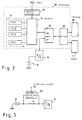
- FIG. 1 is a block diagram of a communication device, preferably a portable telephone, which has a first preferred embodiment of a battery capacity detector according to the present invention.
- a receiver 2 converts a radio signal received by an antenna 1 to a received intermediate frequency (IF) signal.
- An automatic gain controller (AGC) 3 controls the level of the received IF signal to a predetermined level and supplies a level-controlled IF signal to an amplifier 4.
- the amplifier 4 amplifies the level-controlled IF signal to obtain an amplified received IF signal, and outputs the amplified received IF signal to an IF part (not shown).
- an amplifier 5 amplifies a transmitting IF signal which is input from the IF part.
- a transmitter 6 transmits a transmitting radio frequency (RF) signal, obtained by converting an amplified transmitting IF signal, via the antenna 1.
- RF radio frequency
- the transmitter 6 has the function of varying the transmission power of the transmitting RF signal.
- a controller 7 is supplied from the AGC 3 with an AGC signal which is closely related to the electric field of the received signal, and outputs a transmission power control signal which varies the transmission power at the transmitter 6.
- a battery 8 is a power supply for driving the various parts within the telephone set.
- the voltage of the battery 8 is converted in an A/D converter 9 to a digital signal that corresponds to the voltage.
- This digital signal is input to a controller 18.
- the controller 18 compares the input battery voltage with a reference voltage. When the battery voltage dropped to below the reference voltage, the controller 18 causes a battery capacity display 10 to display the drop of the battery capacity, or an alarm 11 to issue an alarm.
- the reference voltage is made variable corresponding to the level of the AGC signal.
- FIG. 2 is a block diagram of a preferred embodiment of the controller 18 shown in FIG. 1.
- a reference voltage source 12 is connected in series with a plurality of resistors R1 to Rn.
- a plurality of voltages V1 to Vn obtained by dividing the reference voltage are taken out from the junctions of the resistors R1 to Rn, and the plurality of voltages V1 to Vn are input to a selector 13.
- a decision circuit 19 inputs an AGC signal from the AGC 3, and outputs a select signal which selects one out of the plurality of voltages in response to the level of the AGC signal.
- the selector 13 selects one out of the plurality of different voltages V1 to Vn in response to the select signal as described later.
- One of the voltages selected by the selector 13 is converted to a digital signal in an A/D converter 14, and is supplied to one of the input nodes of a comparator 15.
- To the other input node of the comparator 15 is input the output of the A/D converter 9 connected to the battery 8.
- the comparison output of the comparator 15 is supplied to a driving circuit 16 which drives the battery capacity display 10 and the alarm 11.
- the controller 7 sends the transmission power control signal to the transmitter 6 to execute the control of the increase in the transmission power of the transmitting RF signal from the transmitter 6. Then, the load of the battery 8 is raised due to the increase in the transmission power, and the voltage of the battery 8 goes down.
- the selector 13 selects one of the plurality of divided voltages V1 to Vn of the reference voltage source 12 based on the level of the AGC signal. In other words, the selection is carried out, based on the electric field intensity, or on the transmission power which is closely related to the electric field intensity.
- a voltage which is roughly inversely proportional to the transmission power, is selected in the selector 13 and is output as a reference voltage.
- the selected reference voltage i.e., one of the divided voltages, is input to the comparator 15 after being converted to the digital signal by the A/D converter 14. This signal is compared in the comparator 15 with the voltage of the battery 8 which is converted to a digital signal by the A/D converter 9.
- a driving signal which drives the battery capacity display 10 and the alarm 11 is supplied to the driving circuit 16 to display and issue an alarm that the battery capacity has dropped.
- the battery load is raised accompanying the increase in the transmission power, the voltage of the battery 8 gces down temporarily.
- a voltage lower than the original reference voltage is also selected as the selected reference voltage, as a result of the increase in the transmission power. Therefore, even when the battery voltage drops due to the increase in the transmission power, the battery voltage in the comparator 15 does not go to a level below the selected reference voltage, avoiding the erroneous detection of the drop in the battery capacity.
- the selector 13 selects a voltage which corresponds to the extent of increase in the transmission power as the selected reference voltage so that it is possible to vary the reference voltage by following the change in the transmission power. Therefore, a temporary drop in the battery voltage will not be judged as a drop in the battery capacity, and it is possible to accurately detect the battery capacity and issue a correct alarm all the time.
- FIG. 3 is a block diagram of another embodiment of the controller 18.
- a plurality of values TH1 to THn of the reference voltage corresponding to a plurality of different transmission powers are stored in advance in a memory 17. Either one of these stored reference values TH1 to THn is selected based on the level of the AGC signal in the selector 13, and supplied to one of the input nodes of the comparator 15.
- the value of the digital signal obtained in a manner similar to the above embodiment by converting the voltage of the battery 8 with the A/D converter 9 is supplied to the other input node of the comparator 15.
- the controller 7 recognizes the electric field intensity based on the AGC signal, and accordingly controls the transmission power.
- the selector 13 in the controller 18 reads from the memory one of the reference values corresponding to the transmission power based on the AGC signal, and uses the selected reference voltage as the reference voltage in the comparator 15. Consequently, even when the battery voltage drops temporarily due to an increase in the transmission power, the reference voltage value is reduced simultaneous with the drop, so that erroneous detection of this state as a drop in the battery capacity and an erroneous issuance of alarm will not take place.
- the reference voltage is selected by the selector in a stepwise manner.
- a constitution may be adopted by which a continuously varying reference voltage is output, and supplied to the comparator.
- the plurality of resistors R1 to Rn may be replaced by a variable resistor, and may control the resistance of the variable resistor in response to the select signal which is based on the AGC signal.
- the transmission power is controlled in response to the electric field intensity, so that the reference voltage is varied by utilizing the AGC signal which is closely related to the transmission power.
- the system may be constituted so as to change and control the reference voltage by directly utilizing the transmission power information.
- the reference voltage may be controlled based on a transmission power control signal from the controller 7.
- the transmission power control signal instead of the AGC signal is supplied to the decision circuit 19 shown in FIG. 2 or 3. Since the remaining configuration and operation of the device shown in FIG. 4 are the same as those of the device shown in FIG. 1, a further description will be omitted.
- the controller 7 controls the transmitter 6 in response to the AGC signal, but the controller 7 may independently control the transmitter 6 without responding to the AGC signal.
- this invention may be provided with a detector for detecting the load, and the device may be constructed so as to vary and control the reference voltage in response to the extent of the load.
- a resistor R is inserted between the battery 8 and the A/D converter 9, and the current flowing in the resistor R is detected by an ammeter 20, a current value detector, or the like.
- the detected current value is supplied to the decision circuit 19 shown in FIG. 2 or 3.
- the decision circuit 19 stores in advance several threshold values, and the detected current value is compared with these threshold values. According to the result of the comparison, the decision circuit 19 sends a select signal to the selector 13 indicating to select an adequate reference voltage.
- the reference voltage with which the detected battery voltage is compared is made to vary in response to the battery load. Since the communication device is so arranged as to lower the reference voltage in response to a drop in the battery voltage caused by an increase in the battery load, the comparison of these voltages will not lead to the judgment of a drop in the battery capacity, and hence an erroneous detection of the battery capacity can be prevented.
Landscapes
- Physics & Mathematics (AREA)
- General Physics & Mathematics (AREA)
- Engineering & Computer Science (AREA)
- Power Engineering (AREA)
- Charge And Discharge Circuits For Batteries Or The Like (AREA)
- Tests Of Electric Status Of Batteries (AREA)
- Transmitters (AREA)
- Mobile Radio Communication Systems (AREA)
- Measurement Of Current Or Voltage (AREA)
Claims (8)
- Dispositif de communication comprenant :caractérisé en ce quedes moyens d'alimentation (8) ;des moyens de détection (9) pour détecter une tension d'alimentation desdits moyens d'alimentation (8) ;des moyens de comparaison (15) pour comparer ladite tension d'alimentation avec une valeur de référence ;des moyens de variation (18) pour faire varier ladite valeur de référence en réponse à une charge sur lesdits moyens d'alimentation (8) ;
lesdits moyens de variation (18) sont adaptés pour faire varier ladite valeur de référence en réponse à un signal de commande automatique de gain (AGC) qui est généré par un circuit de commande automatique de gain (AGC) (3) connecté à un récepteur (2) dudit dispositif de communication et est appliqué à un émetteur (6) dudit dispositif de communication pour commander une puissance de sortie de transmission en réponse audit signal de commande automatique de gain (AGC). - Dispositif de communication selon la revendication 1, dans lequel lesdits moyens de variation (18) augmentent et diminuent de façon continue ladite valeur de référence en réponse à une augmentation ou une diminution de ladite charge.
- Dispositif de communication selon la revendication 1, dans lequel lesdits moyens de variation (18) comprennent :des moyens générateurs (12) pour générer une pluralité de valeurs de référence ; etdes moyens de sélection (13) pour sélectionner une valeur parmi ladite pluralité de valeurs de référence à titre de ladite valeur de référence en réponse à ladite charge.
- Dispositif de communication selon la revendication 1, 2, ou 3, comprenant en outre :un premier moyen de commande (7) pour commander un niveau de sortie d'un signal de transmission dudit émetteur (6).
- Dispositif de communication selon l'une quelconque des revendications 1 à 4, comprenant en outre :des moyens d'information (10, 11) ; etdes moyens d'attaque (16) pour attaquer lesdits moyens d'information (10, 11) lorsque ladite tension d'alimentation est inférieure à ladite valeur de référence.
- Procédé de commande d'une détection d'une capacité restante d'une batterie (8) dans un dispositif de communication, le procédé comprenant les étapes consistant à :caractérisé par le fait dedétecter une tension de batterie de ladite batterie (8) ;sélectionner une valeur de référence en réponse à une charge sur ladite batterie (8) ;comparer ladite tension de batterie avec une valeur de référence sélectionnée ;
sélectionner ladite valeur de référence en réponse à un signal de commande automatique de gain (AGC) qui est généré par un circuit de commande automatique de gain (AGC) (3) connecté à un récepteur (2) dudit dispositif de communication et est appliqué à un émetteur (6) dudit dispositif de communication pour commander une puissance de sortie de transmission en réponse audit signal de commande automatique de gain (AGC). - Procédé selon la revendication 6, le procédé comprenant en outre l'étape consistant à :informer un utilisateur de l'état lorsque ladite tension de batterie est inférieure à ladite valeur de référence sélectionnée.
- Procédé selon les revendications 6 et 7, le procédé comprenant en outre les étapes consistant à :délivrer une pluralité de valeurs de référence ; etsélectionner une valeur parmi ladite pluralité de valeurs de référence.
Applications Claiming Priority (3)
| Application Number | Priority Date | Filing Date | Title |
|---|---|---|---|
| JP6027485A JPH07218562A (ja) | 1994-01-31 | 1994-01-31 | 電源装置 |
| JP27485/94 | 1994-01-31 | ||
| JP2748594 | 1994-01-31 |
Publications (2)
| Publication Number | Publication Date |
|---|---|
| EP0665444A1 EP0665444A1 (fr) | 1995-08-02 |
| EP0665444B1 true EP0665444B1 (fr) | 2002-09-11 |
Family
ID=12222438
Family Applications (1)
| Application Number | Title | Priority Date | Filing Date |
|---|---|---|---|
| EP95101249A Expired - Lifetime EP0665444B1 (fr) | 1994-01-31 | 1995-01-30 | Détecteur de capacité d'une batterie |
Country Status (6)
| Country | Link |
|---|---|
| US (1) | US5610525A (fr) |
| EP (1) | EP0665444B1 (fr) |
| JP (1) | JPH07218562A (fr) |
| AU (1) | AU694749B2 (fr) |
| CA (1) | CA2141401A1 (fr) |
| DE (1) | DE69528090T2 (fr) |
Families Citing this family (7)
| Publication number | Priority date | Publication date | Assignee | Title |
|---|---|---|---|---|
| JP3334028B2 (ja) * | 1996-02-21 | 2002-10-15 | ミノルタ株式会社 | カメラ |
| US5900734A (en) * | 1997-12-22 | 1999-05-04 | Munson; Edward J | Low battery voltage detection and warning system |
| US6624635B1 (en) | 1999-10-23 | 2003-09-23 | Cisco Technology, Inc. | Uninterruptable power supply |
| CN101995553B (zh) * | 2009-08-12 | 2013-06-05 | 中兴通讯股份有限公司 | 电量检测电路、手机待机时手机状态检测处理装置及方法 |
| JP6222423B2 (ja) * | 2013-03-28 | 2017-11-01 | セイコーエプソン株式会社 | 物理量センサー、電子機器及び移動体 |
| JP2017011484A (ja) * | 2015-06-22 | 2017-01-12 | シャープ株式会社 | 無線通信装置 |
| CN116626496A (zh) * | 2022-12-12 | 2023-08-22 | 山东洁源新能源科技发展有限公司 | 一种电池寿命预测模型的建模方法 |
Family Cites Families (11)
| Publication number | Priority date | Publication date | Assignee | Title |
|---|---|---|---|---|
| DE2511681A1 (de) * | 1975-03-18 | 1976-09-30 | Standard Elektrik Lorenz Ag | Einrichtung zur anzeigdes ladezustandes einer batterie mit wechselnden belastungszustaenden |
| JPS6137741A (ja) * | 1984-07-31 | 1986-02-22 | Sagami Chem Res Center | 三重結合の選択的還元方法 |
| JPS63146775U (fr) * | 1987-03-19 | 1988-09-28 | ||
| JPS6459176A (en) * | 1987-08-31 | 1989-03-06 | Seiko Epson Corp | Power source circuit |
| JPH0217830A (ja) * | 1988-07-06 | 1990-01-22 | Oki Electric Ind Co Ltd | 電子機器の電池電圧低下警報制御装置 |
| JP2530717B2 (ja) * | 1989-05-31 | 1996-09-04 | シャープ株式会社 | 電池電圧判別回路 |
| JPH0395610A (ja) * | 1989-09-08 | 1991-04-22 | Toshiba Corp | ローバッテリ状態検出方式 |
| JPH03108679A (ja) * | 1989-09-22 | 1991-05-08 | Aisin Seiki Co Ltd | 放電容量制御回路 |
| JP3063105B2 (ja) * | 1990-01-16 | 2000-07-12 | ソニー株式会社 | 電池残量表示装置 |
| JP2616509B2 (ja) * | 1991-05-07 | 1997-06-04 | 松下電器産業株式会社 | 電気量測定装置 |
| JPH05203684A (ja) * | 1992-01-24 | 1993-08-10 | Sharp Corp | ローバッテリ検出回路 |
-
1994
- 1994-01-31 JP JP6027485A patent/JPH07218562A/ja active Pending
-
1995
- 1995-01-30 CA CA002141401A patent/CA2141401A1/fr not_active Abandoned
- 1995-01-30 DE DE69528090T patent/DE69528090T2/de not_active Expired - Fee Related
- 1995-01-30 EP EP95101249A patent/EP0665444B1/fr not_active Expired - Lifetime
- 1995-01-31 AU AU11481/95A patent/AU694749B2/en not_active Ceased
- 1995-01-31 US US08/381,236 patent/US5610525A/en not_active Expired - Lifetime
Also Published As
| Publication number | Publication date |
|---|---|
| JPH07218562A (ja) | 1995-08-18 |
| AU1148195A (en) | 1995-08-10 |
| DE69528090D1 (de) | 2002-10-17 |
| EP0665444A1 (fr) | 1995-08-02 |
| AU694749B2 (en) | 1998-07-30 |
| CA2141401A1 (fr) | 1995-08-01 |
| US5610525A (en) | 1997-03-11 |
| DE69528090T2 (de) | 2003-01-02 |
Similar Documents
| Publication | Publication Date | Title |
|---|---|---|
| CA2154282C (fr) | Appareil servant a determiner un type de batterie et a modifier ses caracteristiques de fonctionnement | |
| US6313832B1 (en) | Remaining battery capacity display device | |
| AU677135B2 (en) | Method and apparatus for determining external power supply type | |
| US5777399A (en) | Portable electronic apparatus and charge controlling method for portable electronic apparatus | |
| EP0172704B1 (fr) | Appareil de radiocommunication alimenté par batterie, capable de prolonger son état de communication | |
| US5150031A (en) | Battery charging system | |
| US5367242A (en) | System for charging a rechargeable battery of a portable unit in a rack | |
| US5652501A (en) | Voltage sensor for detecting cell voltages | |
| EP2256898B1 (fr) | Bloc-batteries et son chargement | |
| EP0803957B1 (fr) | Batterie rechargeable et systüme pour la charge d'une batterie rechargeable | |
| US6243591B1 (en) | Mobile communication system | |
| EP0665444B1 (fr) | Détecteur de capacité d'une batterie | |
| KR100533574B1 (ko) | 배터리 식별 장치 및 방법 | |
| US6194870B1 (en) | System for automatically indicating that battery should be replaced and method thereof | |
| US5446920A (en) | Variable transmission power type transmitter | |
| JP2956607B2 (ja) | 携帯型無線機 | |
| US5876870A (en) | Battery residual amount display circuit | |
| EP1227330B1 (fr) | Méthode et dispositif de surveillance de la tension d'alimentation | |
| JP2943822B2 (ja) | 無線機の動作電圧制御回路 | |
| JP4404014B2 (ja) | 無線式火災感知システム | |
| JP3459511B2 (ja) | 通信機器用電池残量表示器 | |
| JP4588585B2 (ja) | 無線通信機の受信電界強度信号測定回路。 | |
| JPH06327169A (ja) | 電子機器の予備二次電池充電装置 | |
| KR20000042778A (ko) | 통신단말기의 배터리전압상태 표시방법 | |
| HK1001272A (en) | Apparatus for determining battery type and modifying operating characteristics |
Legal Events
| Date | Code | Title | Description |
|---|---|---|---|
| PUAI | Public reference made under article 153(3) epc to a published international application that has entered the european phase |
Free format text: ORIGINAL CODE: 0009012 |
|
| AK | Designated contracting states |
Kind code of ref document: A1 Designated state(s): DE GB IT SE |
|
| 17P | Request for examination filed |
Effective date: 19950612 |
|
| 17Q | First examination report despatched |
Effective date: 20000703 |
|
| GRAG | Despatch of communication of intention to grant |
Free format text: ORIGINAL CODE: EPIDOS AGRA |
|
| GRAG | Despatch of communication of intention to grant |
Free format text: ORIGINAL CODE: EPIDOS AGRA |
|
| GRAG | Despatch of communication of intention to grant |
Free format text: ORIGINAL CODE: EPIDOS AGRA |
|
| GRAH | Despatch of communication of intention to grant a patent |
Free format text: ORIGINAL CODE: EPIDOS IGRA |
|
| GRAH | Despatch of communication of intention to grant a patent |
Free format text: ORIGINAL CODE: EPIDOS IGRA |
|
| GRAA | (expected) grant |
Free format text: ORIGINAL CODE: 0009210 |
|
| AK | Designated contracting states |
Kind code of ref document: B1 Designated state(s): DE GB IT SE |
|
| REG | Reference to a national code |
Ref country code: GB Ref legal event code: FG4D |
|
| REF | Corresponds to: |
Ref document number: 69528090 Country of ref document: DE Date of ref document: 20021017 |
|
| PG25 | Lapsed in a contracting state [announced via postgrant information from national office to epo] |
Ref country code: SE Free format text: LAPSE BECAUSE OF FAILURE TO SUBMIT A TRANSLATION OF THE DESCRIPTION OR TO PAY THE FEE WITHIN THE PRESCRIBED TIME-LIMIT Effective date: 20021211 |
|
| PGFP | Annual fee paid to national office [announced via postgrant information from national office to epo] |
Ref country code: DE Payment date: 20030130 Year of fee payment: 9 |
|
| PLBE | No opposition filed within time limit |
Free format text: ORIGINAL CODE: 0009261 |
|
| STAA | Information on the status of an ep patent application or granted ep patent |
Free format text: STATUS: NO OPPOSITION FILED WITHIN TIME LIMIT |
|
| 26N | No opposition filed |
Effective date: 20030612 |
|
| PG25 | Lapsed in a contracting state [announced via postgrant information from national office to epo] |
Ref country code: DE Free format text: LAPSE BECAUSE OF NON-PAYMENT OF DUE FEES Effective date: 20040803 |
|
| PG25 | Lapsed in a contracting state [announced via postgrant information from national office to epo] |
Ref country code: IT Free format text: LAPSE BECAUSE OF NON-PAYMENT OF DUE FEES;WARNING: LAPSES OF ITALIAN PATENTS WITH EFFECTIVE DATE BEFORE 2007 MAY HAVE OCCURRED AT ANY TIME BEFORE 2007. THE CORRECT EFFECTIVE DATE MAY BE DIFFERENT FROM THE ONE RECORDED. Effective date: 20050130 |
|
| PGFP | Annual fee paid to national office [announced via postgrant information from national office to epo] |
Ref country code: GB Payment date: 20140129 Year of fee payment: 20 |
|
| REG | Reference to a national code |
Ref country code: GB Ref legal event code: 732E Free format text: REGISTERED BETWEEN 20141023 AND 20141029 |
|
| REG | Reference to a national code |
Ref country code: GB Ref legal event code: PE20 Expiry date: 20150129 |
|
| PG25 | Lapsed in a contracting state [announced via postgrant information from national office to epo] |
Ref country code: GB Free format text: LAPSE BECAUSE OF EXPIRATION OF PROTECTION Effective date: 20150129 |