EP0665474A2 - Elastische Klinge, ihr Herstellungsverfahren und Entwicklungsgerät - Google Patents
Elastische Klinge, ihr Herstellungsverfahren und Entwicklungsgerät Download PDFInfo
- Publication number
- EP0665474A2 EP0665474A2 EP95101224A EP95101224A EP0665474A2 EP 0665474 A2 EP0665474 A2 EP 0665474A2 EP 95101224 A EP95101224 A EP 95101224A EP 95101224 A EP95101224 A EP 95101224A EP 0665474 A2 EP0665474 A2 EP 0665474A2
- Authority
- EP
- European Patent Office
- Prior art keywords
- elastic
- layer
- base layer
- blade
- developing device
- Prior art date
- Legal status (The legal status is an assumption and is not a legal conclusion. Google has not performed a legal analysis and makes no representation as to the accuracy of the status listed.)
- Granted
Links
Images
Classifications
-
- G—PHYSICS
- G03—PHOTOGRAPHY; CINEMATOGRAPHY; ANALOGOUS TECHNIQUES USING WAVES OTHER THAN OPTICAL WAVES; ELECTROGRAPHY; HOLOGRAPHY
- G03G—ELECTROGRAPHY; ELECTROPHOTOGRAPHY; MAGNETOGRAPHY
- G03G15/00—Apparatus for electrographic processes using a charge pattern
- G03G15/06—Apparatus for electrographic processes using a charge pattern for developing
- G03G15/08—Apparatus for electrographic processes using a charge pattern for developing using a solid developer, e.g. powder developer
- G03G15/0806—Apparatus for electrographic processes using a charge pattern for developing using a solid developer, e.g. powder developer on a donor element, e.g. belt, roller
- G03G15/0812—Apparatus for electrographic processes using a charge pattern for developing using a solid developer, e.g. powder developer on a donor element, e.g. belt, roller characterised by the developer regulating means, e.g. structure of doctor blade
-
- G—PHYSICS
- G09—EDUCATION; CRYPTOGRAPHY; DISPLAY; ADVERTISING; SEALS
- G09G—ARRANGEMENTS OR CIRCUITS FOR CONTROL OF INDICATING DEVICES USING STATIC MEANS TO PRESENT VARIABLE INFORMATION
- G09G3/00—Control arrangements or circuits, of interest only in connection with visual indicators other than cathode-ray tubes
- G09G3/20—Control arrangements or circuits, of interest only in connection with visual indicators other than cathode-ray tubes for presentation of an assembly of a number of characters, e.g. a page, by composing the assembly by combination of individual elements arranged in a matrix no fixed position being assigned to or needed to be assigned to the individual characters or partial characters
- G09G3/2007—Display of intermediate tones
- G09G3/2018—Display of intermediate tones by time modulation using two or more time intervals
- G09G3/2022—Display of intermediate tones by time modulation using two or more time intervals using sub-frames
-
- G—PHYSICS
- G09—EDUCATION; CRYPTOGRAPHY; DISPLAY; ADVERTISING; SEALS
- G09G—ARRANGEMENTS OR CIRCUITS FOR CONTROL OF INDICATING DEVICES USING STATIC MEANS TO PRESENT VARIABLE INFORMATION
- G09G3/00—Control arrangements or circuits, of interest only in connection with visual indicators other than cathode-ray tubes
- G09G3/20—Control arrangements or circuits, of interest only in connection with visual indicators other than cathode-ray tubes for presentation of an assembly of a number of characters, e.g. a page, by composing the assembly by combination of individual elements arranged in a matrix no fixed position being assigned to or needed to be assigned to the individual characters or partial characters
- G09G3/2007—Display of intermediate tones
- G09G3/2018—Display of intermediate tones by time modulation using two or more time intervals
- G09G3/2022—Display of intermediate tones by time modulation using two or more time intervals using sub-frames
- G09G3/2033—Display of intermediate tones by time modulation using two or more time intervals using sub-frames with splitting one or more sub-frames corresponding to the most significant bits into two or more sub-frames
-
- Y—GENERAL TAGGING OF NEW TECHNOLOGICAL DEVELOPMENTS; GENERAL TAGGING OF CROSS-SECTIONAL TECHNOLOGIES SPANNING OVER SEVERAL SECTIONS OF THE IPC; TECHNICAL SUBJECTS COVERED BY FORMER USPC CROSS-REFERENCE ART COLLECTIONS [XRACs] AND DIGESTS
- Y10—TECHNICAL SUBJECTS COVERED BY FORMER USPC
- Y10T—TECHNICAL SUBJECTS COVERED BY FORMER US CLASSIFICATION
- Y10T428/00—Stock material or miscellaneous articles
- Y10T428/31504—Composite [nonstructural laminate]
- Y10T428/31678—Of metal
Definitions
- This invention relates to an elastic blade for regulating the layer thickness of a toner, a method of manufacturing the same and a developing device using the elastic blade.
- the thickness of a toner layer on a developing sleep carrying a toner thereon has been regulated by an elastic blade and triboelectricity has been imparted to the toner by friction.
- a blade made of rubber is used as such elastic blade.
- this rubber blade when used for a long period, has caused a variation with time (plasticity deformation) in its elastic material and has suffered from a problem in durability.
- a developing device utilizing, as a blade for regulating the quantity of developer, a blade of two or more layers comprised of an elastic layer for regulating the amount of charge of a developer and a support layer for regulating pressure adhesively secured to the elastic layer.
- the support layer of this blade of two-layer construction is thin and elongate and therefore gives rise to warp.
- this blade is affected by the warp of the support layer and it is difficult to obtain uniform contact pressure in the lengthwise direction of a developing sleeve and therefore, it would occur to mind to form a blade for regulating the quantity of developer which is high in flatness. If the flatness of the blade for regulating the quantity of developer is thus made high, the toner could be uniformly regulated and charged in the whole widthwise direction on the sleeve and the pressure regulation by space saving, low cost and highly accurate setting will not be required.
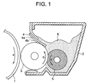
- Figure 1 is a cross-sectional view of a developing device.
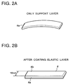
- Figures 2A and 2B show an elastic blade.
- Figure 1 is a cross-sectional view of a developing device according to an embodiment of the present invention.
- a regulating blade 4 which is an elastic blade bears against a developing sleeve 3 which is a toner carrying member opposed to a photosensitive member 3 which is an image bearing member bearing an electrostatic latent image thereon, carrying a toner 6 thereon and being rotated, and regulates the layer thickness of the toner and also imparts triboelectricity to the toner by friction.
- a one-component developer is used as the toner.
- the regulating blade 4 bears against the developing sleeve 3 so as to be in a counter direction to the direction of rotation b of the developing sleeve, that is, so that the free end of the regulating blade 4 which bears against the developing sleeve 3 may be upstream of the end of the regulating blade 4 which is fixed to a developer container 2, with respect to the direction of rotation b.
- the regulating blade 4 of the present embodiment is of a two-layer construction comprising a support layer 4a which is a base layer for regulating pressure and an elastic layer 4b for regulating the amount of charge, and is characterized by a construction in which the elastic layer 4b is formed on the convex side surface of the support layer 4a curved in the lengthwise direction thereof and caused by the warp thereof.
- the method of shaping this regulating blade adopts a method of integrally thermally securing and shaping the elastic layer on the convex side surface of the support layer. At that time, by selecting such a material that the amount of thermal contraction of the elastic layer is greater than the amount of warp of the support layer and the shape of the support layer after the elastic layer has been thermally secured to the support layer becomes warped toward the elastic layer side, it is possible to make a flat regulating blade.
- a member usable as the support layer is a metallic flat plate such as a stainless steel plate, a phosphor bronze plate or an aluminum plate having a thickness preferably in the range of 20 ⁇ m - 500 ⁇ m in connection with the pressure contact force thereof with the developing sleeve, or a flat plate made of resin, for example, a springy hard elastic member such as a polyethylene terephthalate resin plate, a polycarbonate resin plate or a ductile polypropylene resin plate having a thickness preferably in the range of 50 ⁇ m - 100 ⁇ m.
- the warp of SUS stainless steel foil or the like.
- the amount of warp of SUS 60 ⁇ m CSP-H material is about 30 mm for a length of 365 mm.
- the cause of this is the accuracy tolerances of the circumferences of two upper and lower metallic rolls each having a mirror surface when the material is rolled by these two rollers. Therefore, even if the material is wound in advance around a circular paper tube or the like, the direction of warp does not depend on the direction of the winding.
- the amount of warp of a metal such as SUS depends of the thickness thereof and if the thickness is great, the warp thereof will become small in the relation with the distortion thereof.
- a tension-annealed article an article having its amount of warp modified
- the amount of warp will become small for the same thickness (but cost will become higher).
- warp is created as a curl when the scroll is formed and therefore, the direction of warp can be made into the direction of winding.
- the rubber material of the elastic layer may preferably be HTV silicone rubber (such as high-temperature setting type millable silicone rubber), thermoplastic urethane rubber, liquid-like urethane rubber, liquid-like nitrile butadiene rubber or liquid-like silicone rubber (such as LTV or RTV), or an electrically insulative rubber elalstic material such as a denaturalized material or a blended material of the respective materials.
- HTV silicone rubber such as high-temperature setting type millable silicone rubber
- thermoplastic urethane rubber such as high-temperature setting type millable silicone rubber
- liquid-like urethane rubber liquid-like nitrile butadiene rubber or liquid-like silicone rubber
- an electrically insulative rubber elalstic material such as a denaturalized material or a blended material of the respective materials.
- the method of manufacturing the blade can be achieved by applying an adhesive agent to the convex side surface of the support layer for regulating pressure, integrally thermally securing and shaping the elastic layer for contact with the developer by injection molding, press molding or the like, forming it into a sheet of high smoothness, and thereafter cutting the sheet into any desired dimensions, thereby manufacturing the blade.
- the manufacturing method of the present invention is a method of molding the support layer and the elastic layer integrally with each other, and examples thereof include a molding method using a flat plate molding mold using a mirror surface as the upper surface thereof in a flat heat press, to thermoset the elastic layer by heat and pressure and thermally weld it by a primer applied on the support layer (this method is effective when the material of the elastic layer is a material of high viscosity), a molding method of installing the support layer on the outer side in a centrifugal molding machine, applying heat thereto and thermosetting and thermally securing the elastic layer to the support layer while a drum is rotating (this method is effective when the material of the elastic layer is a material of low viscosity), a molding method of pouring a raw material into a metal mold comprising two longitudinally flat plates combined together, and thereafter applying heat thereto, thereby thermosetting the elastic layer and thermally securing it to the support layer (this method is effective when the material of the elastic layer is a material of low viscosity), and
- the magnitude of the amount of warp of the support layer is coped with by changing the molding conditions and the shape conditions.
- a support layer having great warp it is effective to cope with by making the thickness of the elastic layer great and increasing the temperature during the formation of the elastic layer (high temperature molding), and for a support layer having small warp, it is effective to make the thickness of the elastic layer small and effect the molding of the elastic material by low temperature molding (this includes a secondary vulcanizing temperature condition).
- a primer for silicone rubber is applied to the convex side surface thereof, and high temperature setting type LTV silicone rubber (Tore Dowcorning, liquid-like silicone rubber (LSR) DY35-7002) is integrally molded thereon at 120°C for 5 minutes in a metal mold having its upper surface finished into a mirror surface, by an injection molding machine for rubber (produced by Matsuda Works, Ltd.), thereby forming an elastic layer 4b of silicone rubber having a thickness of 0.4 mm on the unwarped surface side of the stainless steel foil. Thereafter, as secondary vulcanization, it is left at it is in environment of 200°C for 4 hours.
- LSR liquid-like silicone rubber
- the molding method is the same as that in Experimental Example 1, and liquid-like rubber is thermoset on SUS foil of a thickness 0.06 mm by injection molding, and a rubber layer of a thickness 0.4 mm is molded in a metal mode.
- a primer is applied to the convex side surface of the SUS foil, and is coated with rubber. Thereafter, it is cut into the dimensions as shown in Figure 2B by a cutting machine, and the cut product is used as a blade for regulating the amount of developer.
- An elastic material sheet is adhesively secured to SUS foil of a thickness 0.06 mm and is molded. At this time, an elastic material sheet already molded by heat molding or the like is adhesively secured to the convex side surface of the SUS foil. As the adhesively securing method at that time, the elastic material is adhesively secured to the SUS foil by the use of a both-surface tape without heat being applied thereto. After the adhesive securing and molding, the molded article is cut as shown in Figure 2B and is used.
- An elastic material sheet is adhesively secured to SUS foil of a thickness 0.06 mm and is molded. At this time, an elastic material sheet already molded by heat molding or the like is adhesively secured to the convex side surface of the SUS foil.
- the adhesively securing method at that time use is made of a hot melt method of molding by applying heat, and the elastic material is adhesively secured to the SUS foil. After the adhesive securing and molding, the molded article is cut as shown in Figure 2B and is used.
- heat adhesive securing molding is preferable as can be seen from the experimental examples.
- This specification discloses an elastic blade for regulating the layer thickness of a toner used in the developing device of an image forming apparatus such as an electrophotographic apparatus.
- the elastic blade is provided with a base layer and an elastic layer provided on the convex surface side of the base layer, and is high in flatness.
Landscapes
- Physics & Mathematics (AREA)
- General Physics & Mathematics (AREA)
- Dry Development In Electrophotography (AREA)
Applications Claiming Priority (2)
| Application Number | Priority Date | Filing Date | Title |
|---|---|---|---|
| JP987594A JPH07219339A (ja) | 1994-01-31 | 1994-01-31 | 弾性ブレード及びその製造方法及び現像装置 |
| JP9875/94 | 1994-01-31 |
Publications (3)
| Publication Number | Publication Date |
|---|---|
| EP0665474A2 true EP0665474A2 (de) | 1995-08-02 |
| EP0665474A3 EP0665474A3 (de) | 1996-05-15 |
| EP0665474B1 EP0665474B1 (de) | 1999-04-07 |
Family
ID=11732333
Family Applications (1)
| Application Number | Title | Priority Date | Filing Date |
|---|---|---|---|
| EP19950101224 Expired - Lifetime EP0665474B1 (de) | 1994-01-31 | 1995-01-30 | Elastische Klinge, ihr Herstellungsverfahren und Entwicklungsgerät |
Country Status (4)
| Country | Link |
|---|---|
| US (1) | US6475421B2 (de) |
| EP (1) | EP0665474B1 (de) |
| JP (1) | JPH07219339A (de) |
| DE (1) | DE69508814T2 (de) |
Cited By (2)
| Publication number | Priority date | Publication date | Assignee | Title |
|---|---|---|---|---|
| US7239832B2 (en) | 2003-07-17 | 2007-07-03 | Canon Kabushiki Kaisha | Developer regulation member and developing apparatus |
| WO2010121544A1 (zh) * | 2009-04-24 | 2010-10-28 | 珠海天威飞马打印耗材有限公司 | 显影剂层厚调节器 |
Families Citing this family (6)
| Publication number | Priority date | Publication date | Assignee | Title |
|---|---|---|---|---|
| JP4659233B2 (ja) * | 2001-02-27 | 2011-03-30 | キヤノン株式会社 | 現像剤規制部材、現像装置、プロセスカートリッジ及び画像形成装置 |
| KR100421979B1 (ko) * | 2002-06-12 | 2004-03-11 | 삼성전자주식회사 | 현상제층 규제장치 및 그 제조방법 |
| US8043081B2 (en) * | 2005-10-17 | 2011-10-25 | Bridgestone Corporation | Mold for forming developer blade, and developer blade formed with same |
| CN102126135B (zh) * | 2010-11-12 | 2012-11-21 | 四川朗迪塑胶电器有限公司 | 一种金属风扇叶轮自动成型机 |
| CN113085101B (zh) * | 2021-03-26 | 2022-08-23 | 四川长虹空调有限公司 | 一种空调摆叶的制备方法 |
| JP7746043B2 (ja) * | 2021-06-25 | 2025-09-30 | キヤノン株式会社 | 規制部材、現像装置、プロセスカートリッジ、および、画像形成装置 |
Family Cites Families (25)
| Publication number | Priority date | Publication date | Assignee | Title |
|---|---|---|---|---|
| US3077658A (en) * | 1960-04-11 | 1963-02-19 | Gen Dynamics Corp | Method of manufacturing molded module assemblies |
| US3246066A (en) * | 1963-04-17 | 1966-04-12 | Jules P Gits | Method of making three dimensional molded articles |
| US4247196A (en) | 1978-04-26 | 1981-01-27 | Minolta Camera Kabushiki Kaisha | Cleaning device for use in electrophotographic copying machines |
| JPS6051856A (ja) * | 1983-08-31 | 1985-03-23 | Toshiba Corp | 現像装置 |
| JPS6053972A (ja) * | 1983-09-05 | 1985-03-28 | Fuji Xerox Co Ltd | 現像装置 |
| JPS6093469A (ja) | 1983-10-28 | 1985-05-25 | Toshiba Corp | 現像装置 |
| JPS6128973A (ja) * | 1984-07-20 | 1986-02-08 | Fuji Xerox Co Ltd | 非磁性一成分現像装置 |
| JPS6129866A (ja) * | 1984-07-20 | 1986-02-10 | Fuji Xerox Co Ltd | 非磁性一成分現像装置 |
| DE3614191A1 (de) * | 1985-06-27 | 1987-01-08 | Man Technologie Gmbh | Verfahren zur bildung einer oberflaeche hoher guete auf einem bauteil |
| US4814818A (en) | 1986-10-09 | 1989-03-21 | Konishiroku Photo Industry Co., Ltd. | Developer layer forming apparatus |
| EP0300456A3 (de) * | 1987-07-24 | 1990-08-08 | Bruce H. Faaland | Ablauffolgeplanungsverfahren und System |
| JPH03216682A (ja) * | 1990-01-22 | 1991-09-24 | Ricoh Co Ltd | 現像装置 |
| JP2801349B2 (ja) | 1990-03-24 | 1998-09-21 | キヤノン株式会社 | クリーニングブレード及びその製造方法及びクリーニングブレードを有するクリーニング装置 |
| JP2962843B2 (ja) | 1990-06-07 | 1999-10-12 | キヤノン株式会社 | クリーニングブレード及びこれを用いた装置 |
| JP2675916B2 (ja) | 1990-11-30 | 1997-11-12 | 富士通株式会社 | 現像装置 |
| JP2853373B2 (ja) | 1991-05-21 | 1999-02-03 | 富士ゼロックス株式会社 | 一成分現像装置 |
| US5223604A (en) * | 1991-06-25 | 1993-06-29 | S.P.I. Synthetic Peptides Incorporated | Pseudomonas exoenzyme s peptide composition and method |
| JPH05232792A (ja) | 1992-02-20 | 1993-09-10 | Canon Inc | 現像装置 |
| JPH06258934A (ja) * | 1993-03-09 | 1994-09-16 | Canon Inc | 弾性現像剤量規制ブレード部材及びその製造方法 |
| EP0619530B1 (de) | 1993-03-31 | 1999-11-03 | Canon Kabushiki Kaisha | Entwicklungsgerät mit elastischer Klinge |
| JPH06348119A (ja) | 1993-06-10 | 1994-12-22 | Canon Inc | 現像装置 |
| JP3016331B2 (ja) * | 1993-09-07 | 2000-03-06 | 富士通株式会社 | 電子機器筐体の製造方法 |
| US5997675A (en) * | 1994-07-29 | 1999-12-07 | Sekisui Kagaku Kogyo Kabushiki Kaisha | Method of molding using a covering sheet having minute unevenness on the surface thereof |
| KR100198813B1 (ko) * | 1996-06-12 | 1999-06-15 | 정선종 | 우편경로 시스템 및 그 시스템에 따른 최단 경로 생성방법 |
| US5978636A (en) * | 1998-02-26 | 1999-11-02 | Canon Kabushiki Kaisha | Developer amount restricting member and developing device |
-
1994
- 1994-01-31 JP JP987594A patent/JPH07219339A/ja active Pending
-
1995
- 1995-01-30 EP EP19950101224 patent/EP0665474B1/de not_active Expired - Lifetime
- 1995-01-30 DE DE69508814T patent/DE69508814T2/de not_active Expired - Lifetime
-
2001
- 2001-06-18 US US09/881,667 patent/US6475421B2/en not_active Expired - Fee Related
Cited By (2)
| Publication number | Priority date | Publication date | Assignee | Title |
|---|---|---|---|---|
| US7239832B2 (en) | 2003-07-17 | 2007-07-03 | Canon Kabushiki Kaisha | Developer regulation member and developing apparatus |
| WO2010121544A1 (zh) * | 2009-04-24 | 2010-10-28 | 珠海天威飞马打印耗材有限公司 | 显影剂层厚调节器 |
Also Published As
| Publication number | Publication date |
|---|---|
| JPH07219339A (ja) | 1995-08-18 |
| EP0665474A3 (de) | 1996-05-15 |
| DE69508814T2 (de) | 1999-11-11 |
| US20010041264A1 (en) | 2001-11-15 |
| EP0665474B1 (de) | 1999-04-07 |
| DE69508814D1 (de) | 1999-05-12 |
| US6475421B2 (en) | 2002-11-05 |
Similar Documents
| Publication | Publication Date | Title |
|---|---|---|
| US6163669A (en) | Image forming apparatus | |
| CA1067132A (en) | Fuser roll having a non-uniform cross section | |
| JP4977517B2 (ja) | 現像剤量規制ブレードと現像剤量規制ブレードの製造方法 | |
| US5933692A (en) | Developer regulating member with elastic layer supporting section having high elastic limit value and developing apparatus using the same | |
| EP0665474B1 (de) | Elastische Klinge, ihr Herstellungsverfahren und Entwicklungsgerät | |
| US5729806A (en) | Curved developer amount controlling member, developing apparatus, and process cartridge using the same | |
| US4050886A (en) | Roll fuser | |
| EP0046849A1 (de) | Schmelzwalzenfixierer für ein elektrophotographisches Gerät | |
| US5713120A (en) | Method of manufacturing a blade for regulating the thickness of a developing agent | |
| US7016633B2 (en) | Developing assembly featuring a developer-carrying member having specified ranges of deformation and hardness and a developer quality control blade having a rough contact surface | |
| EP0469518B1 (de) | Tonerabdichtungsmaterial | |
| JP5177988B2 (ja) | 現像剤量規制ブレード及びこれを用いた現像装置 | |
| JP3106028B2 (ja) | 現像剤量規制部材及びその製造方法そしてこの部材を備える現像装置 | |
| JP3514028B2 (ja) | 電子写真複写機用ロール | |
| JPH0869171A (ja) | 電子写真印刷装置 | |
| JPH0120745B2 (de) | ||
| JP2007293106A (ja) | 現像剤量規制ブレードおよびそれを搭載した現像装置 | |
| JPH0143310B2 (de) | ||
| KR100421979B1 (ko) | 현상제층 규제장치 및 그 제조방법 | |
| JP2002116622A (ja) | 現像剤量規制部材および現像装置 | |
| JP2001117406A (ja) | 定着ロールおよび定着ロール製造方法 | |
| JP3046627B2 (ja) | トナー像定着装置用加圧ローラの製造方法 | |
| JP2002278260A (ja) | 電子写真装置用現像ブレ−ド及びその製造方法 | |
| JP2007232893A (ja) | 現像剤量規制ブレードの製造方法 | |
| JPH09274378A (ja) | 現像剤量規制部材およびその製造方法、現像装置、および電子写真装置 |
Legal Events
| Date | Code | Title | Description |
|---|---|---|---|
| PUAI | Public reference made under article 153(3) epc to a published international application that has entered the european phase |
Free format text: ORIGINAL CODE: 0009012 |
|
| AK | Designated contracting states |
Kind code of ref document: A2 Designated state(s): DE ES FR GB IT |
|
| PUAL | Search report despatched |
Free format text: ORIGINAL CODE: 0009013 |
|
| AK | Designated contracting states |
Kind code of ref document: A3 Designated state(s): DE ES FR GB IT |
|
| 17P | Request for examination filed |
Effective date: 19960927 |
|
| 17Q | First examination report despatched |
Effective date: 19971223 |
|
| GRAG | Despatch of communication of intention to grant |
Free format text: ORIGINAL CODE: EPIDOS AGRA |
|
| GRAG | Despatch of communication of intention to grant |
Free format text: ORIGINAL CODE: EPIDOS AGRA |
|
| GRAH | Despatch of communication of intention to grant a patent |
Free format text: ORIGINAL CODE: EPIDOS IGRA |
|
| GRAH | Despatch of communication of intention to grant a patent |
Free format text: ORIGINAL CODE: EPIDOS IGRA |
|
| GRAA | (expected) grant |
Free format text: ORIGINAL CODE: 0009210 |
|
| AK | Designated contracting states |
Kind code of ref document: B1 Designated state(s): DE ES FR GB IT |
|
| PG25 | Lapsed in a contracting state [announced via postgrant information from national office to epo] |
Ref country code: ES Free format text: THE PATENT HAS BEEN ANNULLED BY A DECISION OF A NATIONAL AUTHORITY Effective date: 19990407 |
|
| REF | Corresponds to: |
Ref document number: 69508814 Country of ref document: DE Date of ref document: 19990512 |
|
| ET | Fr: translation filed | ||
| PLBE | No opposition filed within time limit |
Free format text: ORIGINAL CODE: 0009261 |
|
| STAA | Information on the status of an ep patent application or granted ep patent |
Free format text: STATUS: NO OPPOSITION FILED WITHIN TIME LIMIT |
|
| 26N | No opposition filed | ||
| REG | Reference to a national code |
Ref country code: GB Ref legal event code: IF02 |
|
| PGFP | Annual fee paid to national office [announced via postgrant information from national office to epo] |
Ref country code: IT Payment date: 20100120 Year of fee payment: 16 Ref country code: FR Payment date: 20100210 Year of fee payment: 16 |
|
| PGFP | Annual fee paid to national office [announced via postgrant information from national office to epo] |
Ref country code: GB Payment date: 20100126 Year of fee payment: 16 Ref country code: DE Payment date: 20100131 Year of fee payment: 16 |
|
| GBPC | Gb: european patent ceased through non-payment of renewal fee |
Effective date: 20110130 |
|
| REG | Reference to a national code |
Ref country code: FR Ref legal event code: ST Effective date: 20110930 |
|
| PG25 | Lapsed in a contracting state [announced via postgrant information from national office to epo] |
Ref country code: FR Free format text: LAPSE BECAUSE OF NON-PAYMENT OF DUE FEES Effective date: 20110131 |
|
| PG25 | Lapsed in a contracting state [announced via postgrant information from national office to epo] |
Ref country code: GB Free format text: LAPSE BECAUSE OF NON-PAYMENT OF DUE FEES Effective date: 20110130 |
|
| REG | Reference to a national code |
Ref country code: DE Ref legal event code: R119 Ref document number: 69508814 Country of ref document: DE Effective date: 20110802 |
|
| PG25 | Lapsed in a contracting state [announced via postgrant information from national office to epo] |
Ref country code: IT Free format text: LAPSE BECAUSE OF NON-PAYMENT OF DUE FEES Effective date: 20110130 |
|
| PG25 | Lapsed in a contracting state [announced via postgrant information from national office to epo] |
Ref country code: DE Free format text: LAPSE BECAUSE OF NON-PAYMENT OF DUE FEES Effective date: 20110802 |