EP0666115A2 - Procédé de tri de particules en vrac et dispositif à cet effet - Google Patents
Procédé de tri de particules en vrac et dispositif à cet effet Download PDFInfo
- Publication number
- EP0666115A2 EP0666115A2 EP94105931A EP94105931A EP0666115A2 EP 0666115 A2 EP0666115 A2 EP 0666115A2 EP 94105931 A EP94105931 A EP 94105931A EP 94105931 A EP94105931 A EP 94105931A EP 0666115 A2 EP0666115 A2 EP 0666115A2
- Authority
- EP
- European Patent Office
- Prior art keywords
- particles
- bulk material
- base
- color
- signal
- Prior art date
- Legal status (The legal status is an assumption and is not a legal conclusion. Google has not performed a legal analysis and makes no representation as to the accuracy of the status listed.)
- Withdrawn
Links
Images



Classifications
-
- B—PERFORMING OPERATIONS; TRANSPORTING
- B07—SEPARATING SOLIDS FROM SOLIDS; SORTING
- B07C—POSTAL SORTING; SORTING INDIVIDUAL ARTICLES, OR BULK MATERIAL FIT TO BE SORTED PIECE-MEAL, e.g. BY PICKING
- B07C5/00—Sorting according to a characteristic or feature of the articles or material being sorted, e.g. by control effected by devices which detect or measure such characteristic or feature; Sorting by manually actuated devices, e.g. switches
- B07C5/36—Sorting apparatus characterised by the means used for distribution
-
- B—PERFORMING OPERATIONS; TRANSPORTING
- B07—SEPARATING SOLIDS FROM SOLIDS; SORTING
- B07C—POSTAL SORTING; SORTING INDIVIDUAL ARTICLES, OR BULK MATERIAL FIT TO BE SORTED PIECE-MEAL, e.g. BY PICKING
- B07C5/00—Sorting according to a characteristic or feature of the articles or material being sorted, e.g. by control effected by devices which detect or measure such characteristic or feature; Sorting by manually actuated devices, e.g. switches
- B07C5/34—Sorting according to other particular properties
- B07C5/342—Sorting according to other particular properties according to optical properties, e.g. colour
- B07C5/3425—Sorting according to other particular properties according to optical properties, e.g. colour of granular material, e.g. ore particles, grain
-
- B—PERFORMING OPERATIONS; TRANSPORTING
- B07—SEPARATING SOLIDS FROM SOLIDS; SORTING
- B07C—POSTAL SORTING; SORTING INDIVIDUAL ARTICLES, OR BULK MATERIAL FIT TO BE SORTED PIECE-MEAL, e.g. BY PICKING
- B07C5/00—Sorting according to a characteristic or feature of the articles or material being sorted, e.g. by control effected by devices which detect or measure such characteristic or feature; Sorting by manually actuated devices, e.g. switches
- B07C5/36—Sorting apparatus characterised by the means used for distribution
- B07C5/361—Processing or control devices therefor, e.g. escort memory
-
- B—PERFORMING OPERATIONS; TRANSPORTING
- B07—SEPARATING SOLIDS FROM SOLIDS; SORTING
- B07C—POSTAL SORTING; SORTING INDIVIDUAL ARTICLES, OR BULK MATERIAL FIT TO BE SORTED PIECE-MEAL, e.g. BY PICKING
- B07C5/00—Sorting according to a characteristic or feature of the articles or material being sorted, e.g. by control effected by devices which detect or measure such characteristic or feature; Sorting by manually actuated devices, e.g. switches
- B07C5/36—Sorting apparatus characterised by the means used for distribution
- B07C5/363—Sorting apparatus characterised by the means used for distribution by means of air
- B07C5/365—Sorting apparatus characterised by the means used for distribution by means of air using a single separation means
Definitions
- the invention relates to a method for sorting particles of a bulk or bulk good according to the preamble of claim 1.
- Such a method or a device therefor has become known, for example, from GB-PS 1 393 061.
- the bulk material is on a conveyor belt, over which a video camera is provided, and at the end of which a number of individually operable nozzles are arranged transversely to the width of the conveyor belt. Deviations in the brightness of the particles on the conveyor belt are determined by means of the video camera and one of the air nozzles is actuated via a comparison circuit with a corresponding delay in order to eject the relevant particle from the path of the bulk material and thereby to sort it out.
- the disadvantage of this arrangement is that the camera is only able to detect faults on the side of the particles facing it, so that it misses faults on another side (in particular the opposite side). Ultimately, therefore, the poorly sorted particles included those of poor quality.
- the invention has for its object to provide a device for sorting particles of a bulk material, which ensures precise ejection of the particles to be sorted out by a more precise check.
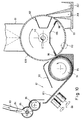
- the pre-reading device has a video camera 1, which is arranged above a bulk material flow moving on a base 2. At the end of the base 2 there is a deflection device 3, which is able to direct the current in two paths.
- the particles recognized as "good” pass in a larger flow 4 into a guide 5, whereas a partial flow of the bulk material moving on the base 2 branches off and reaches a funnel 6.
- the video camera has a target 20, preferably in the form of at least one diode row, to which a corresponding row of switches 21 for querying the individual diodes or pixels and a shift register 22 controlling them are connected.
- a target 20 preferably in the form of at least one diode row, to which a corresponding row of switches 21 for querying the individual diodes or pixels and a shift register 22 controlling them are connected.
- bucket chain circuits bucket brigade devices
- charge couplers charge coupled devices
- the video signal queried via the switches 21 passes via a line 23 into a merely indicated amplifier circuit 24, which is followed by a video processing stage 25.
- the slide register 22 is part of the deflection circuit with a clock generator 26, a counter 27 and a start or reset pulse generator 28 for controlling the shift register 22.
- an evaluation stage 30 may be provided.
- the video signal from stage 25 and the localization signal from stage 29 or 30 are fed to a comparison or coincidence stage 31, which detects at which pixel this occurs when an error signal (brightness or color of a particle does not correspond to the target area)
- An error occurs, ie at which point of the scanning area 17 of the video camera 1 indicated by dash-dotted lines in FIG. 1 the defective particle was observed.
- Via an evaluation circuit 32 is a row of switches, shown only as a block 33, via which the actuator 34 corresponding to the respective location with the defective particle (only one is shown) can be controlled.
- This actuating member 34 already forms part of the deflection device 3.
- the deflection device 3 has a series of flaps 35 and 35 'via shafts 37 arranged on an inlet funnel 36. Each flap 35 and 35 'can take two positions. In one position 35, the bulk material is passed over the inlet funnel 6 and thus falls into the guide 5 as stream 4. In contrast, in the other position 35 ', the inlet funnel 36 is opened, so that a partial flow corresponding to the width of the flap or the shaft 37 of the bulk material is passed into the funnel 6 via the respective shaft 37.
- a light-electric converter 18 is arranged in the beam path of the incident light lamp 15, its output signal is compared in a comparison and control circuit 29 with a target value and the brightness of the lamp 15 is adjusted if necessary in such a way that it corresponds to the desired target value.
- the deflection rollers 39, 40 are preferably formed by two truncated cones, the smaller base areas of which are connected to one another.
- the belt 38 is approximately V-shaped, so that the falling particles certainly remain at a certain point, namely in the middle of the conveyor belt 38.
- a further video camera 101 is arranged above the conveyor belt 38, which in principle can be similar to the video camera 1. However, it is preferably connected to an image analysis computer 41, the output of this computer being connected to an actuator circuit 42 is connected.
- the actuator circuit 42 has two control outputs 43, 44, which each lead to one of two air nozzles 45, 46 and control the supply of air (not shown) there.
- the two air nozzles 45, 46 are connected in series so that they can optionally be used to blow a certain particle out of the path of the conveyor belt 38. Accordingly, the two air nozzles 45, 46 have orientations oriented in different directions, and each of these air nozzles 45, 46 is assigned its own storage container 47 or 48, the air nozzle 45, in the manner shown in broken lines, throwing the particles into the storage container 47, which Air nozzle 46 into the reservoir 48.
- air nozzles 145, 145 'and 146, 146' are arranged in the region of a deflection roller 140.
- the band 138 is guided flat.
- the deflection roller 140 is divided and has a further roller part 140 'on a common shaft 49.
- the nozzles 145 to 146 ' are arranged in a stationary manner and are oriented in such a way that they blow in different directions, indicated by dash-dot lines.
- a drum-shaped deflection roller 240 is provided for the belt 238, to which drum-shaped deflection roller 240 air is supplied via a hollow shaft 249.
- Air nozzles 245 are arranged within the deflecting roller 240, which rotate with the drum-shaped deflecting roller 240 and whose outlet openings are provided on the surface of the drum circumference.
- it is necessary to provide a valve circuit for each of the individual air nozzles which means that air is only blown out at those air nozzles that have reached the positions shown in FIG. 2.
- Such a valve circuit is not shown, but it is clear to the person skilled in the art that corresponding sliding contacts for the power supply of solenoid valves must be provided for this.
- FIG. 4 shows a band 238 with a plurality of depressions 50 arranged next to one another, which are each intended to receive a bulk material particle, such as a grain of rice. These depressions 50 ensure that a plurality of particles lying next to one another in a row also assume an ordered, predetermined position.
- Belt 238 is assumed to transport the particles from top to bottom (based on FIG. 4), whereby they are passed through the field of view 17 of a video camera (not shown here). Since the bulk material particles, at least in the case of natural products, usually have a color mixed with shades of gray, it is advantageous if the band 238 is kept in a full color or in a contrasting color, such as blue.
- At least one lighting device 115 for example in the form of a fluorescent tube, is expediently provided, and in particular even two of them, as shown in FIG. 6, but daylighting can be a disruptive influence, such as fluctuations in voltage or current in the power supply. In order to eliminate these influencing variables, numerous suggestions have been made for regulating the background brightness. But here another path is taken.
- video cameras normally work with additive mixing of the colors, in which case the colors mentioned are used. This mixing method is also for the purposes of the present invention the preferred.
- color stripe filters in which case a subtractive color mixture is used, in which case the colors red, blue and yellow or magenta, cyan and yellow are used, which is also possible for the present purposes , but is not preferred.
- the belt 238 naturally runs at a precisely known, and preferably regulated, speed.
- the accuracy of the nozzle control is further improved if the band 238 has timing markings 52 at predetermined intervals, suitably assigned to the depressions 50. These timing markings are shown here on either side of band 238, but it will generally suffice for such markings to be provided only on one of the band edges. The markings could also be placed at some other point, such as in the middle of the band, but the assignment of the signals derived from them is easier if the markings 52 are on the edge.
- clock markings 52 it is also possible to attach a further observation camera or (better) an observation mirror - viewed in the direction of movement of the belt 238 - behind the blow-out nozzles 145, 146 (or any other sorting device) in order to check whether a was not sorted out as a poorly recognized particle, for example because of speed errors, and in order to be able to correct the speed of the belt 238 accordingly.
- the arrangement of an additional camera means an additional effort, whereas the reflection (which can also only take place over part of the image field) may result in the monitoring in the region 17 being interrupted during the duration of the reflection, which results in a sorting out for safety reasons of all particles not controlled during this time.
- blow-out nozzles 145, 146 are multiple nozzles, i.e. correspond to a row of nozzles arranged transversely to the longitudinal extent of the belt, because each depression 50 holding a particle must be assigned a separate and separately controllable individual nozzle if one does not want to accept that in addition to a bad particle, the adjacent good particles are also separated out.
- the hand 238 can consist of an air-permeable base fabric 53 with a coating 54 applied thereon (the latter consisting of the aforementioned tone of a full color, such as blue (rare in natural products).
- this coating 54 is in the area of the depressions 50, so that only the bare tissue 53 forms the substrate carrying the respective particle at these points.
- a first band 338 with a video camera 201 is provided, to which corresponding lighting devices 115 are assigned, and to which a corresponding number of blow-out nozzles 45, 46 (only two are shown, but if desired only one may be sufficient) are.
- blow-out nozzles 45, 46 separate the particles which are recognized as undesirable when the particles are viewed only from one side, while the rest of the particles are carried on by the belt 338.
- the particles then reach the area of a turning station 55, in which a second belt 438 is guided closely over the belt 238, so that after both belts have been deflected by a number of deflecting rollers 56, the position is reversed at the end of this turning station, i.e. the second band 438 is no longer above band 338, but below it. Due to the close guidance of the two belts 338, 438 lying against one another, the bulk material particles are placed in unchanged mutual assignment from one belt to the other and thereby turned through 180 °, so that their previously invisible side can now be viewed by a similar video camera 301, which also controls blow nozzles (not shown here), which can be arranged, for example, on the roller 240 (cf. FIG. 3).
- Such a conventional solid-state or tube camera for the delivery of color signals generally has six outputs, namely an output 57 for the horizontal deflection signal (this expression should also include the corresponding signal from a solid-state camera), an output 58 for the vertical deflection signal, and an output 59 for the Red signal, an output 60 for the blue signal, and an output 61 for the green signal. There is also an output 62 for the Y signal (brightness).
- the reference pattern 51 and the clock markings 52 are arranged at predetermined locations and therefore the signal sections corresponding to these references 51, 52 will appear at a very specific location within the video signal during a deflection period. If the lines 57, 58 are therefore fed to a switchover stage 67, the latter can use these deflection signals to determine whether the incoming signal comes from such a reference point 51 or 52 or from another point. Accordingly, the signals are divided by the switching stage, namely the reference signal originating from the reference pattern 51 is emitted into a reference storage stage 68, the signal originating from the tape surface, with the exception of the clock mark signals, is sent to a stage 69, whereas the clock mark signals reach an output line 70.
- a comparison stage 71 The inputs of a comparison stage 71 are connected to the outputs of stages 68, 69, which compensates for any irregularities or changes in the brightness of the background by forming differences, so that readjustment of the lighting is no longer necessary. It is advantageous if a further difference is formed which is based on the ability of the circuit to learn.
- a switchover stage 72 may be provided at the output of the comparison circuit 71 (or, if this is not provided because background control according to the prior art is preferred, at the output of the camera 101 or stage 69).
- this switch stage has (but not necessarily) a switchable control input 73, so that its switchover can be controlled via a selector switch S1 by a timing element 74, which automatically switches the switchover device to normal operation after a time corresponding to the passage of the reference sample, or that Switching can, depending on the position of the selector switch S1, also be carried out manually by means of a manual switch S2, the opening or closing of which switches over the stage 72.
- a manual control is particularly advantageous if the time for the, preferably adjustable, timer 74 cannot be determined exactly from the start (for example, a sample of particles is sent a few days in advance so that it can be sorted out later).
- a learning operation or normal operation is carried out, with at least one memory 75 being connected in the former case, which is preferably designed as a non-volatile memory (e.g. floppy disk).
- a non-volatile memory e.g. floppy disk.
- the memory 75 is connected to the memory 68 in order to be able to correct its content as a function of the illumination color of the standardized color pattern 51 (FIG. 4) and thus to avoid reading errors.
- the connecting line drawn in broken lines between the two memories 68 and 75 forms the simpler way of a corresponding correction.
- the switching stage 72 - controlled by the timer 74 or the switch S2 - switches to normal operation, it delivers the signals received to a buffer stage 76 lying parallel to the memory 75 or directly to one input of a comparison and control stage 77, the other input of which is connected to the outputs of the reference signal memory 75.
- the comparison stage 77 expediently has a predetermined and expediently adjustable threshold value, so that it does not provide any output signal in the event that the quality of the checked particles lies within a certain tolerance range. However, depending on the type of deviation, See will deliver a signal to a switching stage 78 if this signal indicates a deviation outside the tolerance range lies.
- the switchover stage 78 which can be switched from one state to the other via an actuation line, the signal supplied to it via an output 80 is used to switch one of two actuation stages 81 or 82, each with a corresponding valve as an actuator for actuating the nozzle 45 or 46 to control.
- the clock signal line 70 is connected to the comparison and control stage 77.
- the line 80 does not directly control the switchover stage 78, but that a form processor Fp is also linked to the line 80.
- This form processor Fp receives the output signal of the difference former 77, expediently via an inverter stage Iv. If, as described above, if the vectorial difference generator 77 does not provide any output signal for good particles and only emits one for bad particles, the shape processor Fp is activated via the inverter Iv only in the case of particles of good color, which prevents its operation ( compared to a possible parallel operation of the difference generator and form processor).
- stages 77 and Fp there is a logical link log, which is simply represented here as an OR operation, and which actuates the switching stage 78 as a function of the signals from both stages 77 and Fp.
- a logical link log which is simply represented here as an OR operation, and which actuates the switching stage 78 as a function of the signals from both stages 77 and Fp.
- more than just two ejection devices 44, 46 will then generally be arranged one behind the other in order to be able to sort out according to colors and sizes or qualities.
- the advantages of the underlay according to the invention can at least partially also be effective if the bulk material particles are not brought into an ordered position, but rather at least a predetermined speed is secured by the conveyor belt.
- the difference formation method with which the checking device according to the invention works can be advantageous regardless of the use of the method according to the invention, and the same applies analogously to a learning device for entering the color parameters, as was described with reference to FIG. 7, but now with reference to FIG 7A and 7B to be described in more detail.
- FIG. 7A shows a three-dimensional axis system with a brightness axis I, a saturation axis H and a hue axis S.
- the hues to be found on a good particle in the form of a " Arrange color cloud "P '.
- the background could also be calculated via the deflection signals, since the openings 50 lying next to one another will probably always pass successively at the same location, and the presence of a number of particles can also be determined via the clock signals 52, but this is due to excessive inaccuracies connected, especially since it can also happen that an opening 50 is not occupied at all (and then probably emits a background color).
- the reference signal for red R ref the reference signal for blue
- IHS the axis system
- These reference signals can then be checked, expediently at least at the start of operation, but possibly also at periodic intervals, by calling up the output signal of the memory 68, in which the respective color signal taken from the standard color pattern 51 is present, and using the stored value R ref , B ref and G ref is compared.
- FIG. 7B shows the structure of the memory 75 in a preferred embodiment as a three-dimensional histogram processor.
- the IHS- Signal to an addressable memory 75 ', in the learning step of a read-increment-write stage RIW is operated until a first version of the color reference values P 'and 38''(FIG. 7A) is stored.
- this first version of the determined values for P 'and 38''could already be used to sort out particles. It may be the case, however, that due to statistical errors, color tones appear that do not actually belong to the reference value bundle P 'or 38'', for example due to local discoloration. These hues will then have occurred only sporadically over the area under consideration and therefore only make up a small part of the statistically collected color values.
- the threshold value can expediently be set by means of an adjusting resistor R1
- all the underrepresented color tones become from the Statistics are eliminated, and a revised version of the value bundles P 'and 38''is obtained, which is then re-entered into the memory 75' by the output of the threshold switch S th .
- the switch S3 can then be opened and the adjusted values can be read out to the vectorial difference generator 77.
- material to be sorted out is conveyed, for example, via an inlet shaft 83, which expediently has a metering element, e.g. in the form of a flap 84 which changes the shaft cross section, to a distribution device 85.
- a metering element e.g. in the form of a flap 84 which changes the shaft cross section
- the arrangement can be made in a manner similar to that in FIGS. 10 to 13 of US Pat. No. 4,905,917 using the device 30 and a feed roller connected downstream 8 is shown, wherein in the case of the present FIG. 8A, the feed roller 86 is connected directly downstream of the distribution rotor 85.
- a vibration conveyor 87 with a vibration drive 88 is expediently provided for preparing the separation, it being advantageous if the vibration conveyor 87 in the longitudinal direction of the conveyor has individual feed channels 87.1 which expediently run parallel to one another and which already separate individual rows of successive particles from one another by the channels 87.1 each having a width which corresponds to a particle width.
- the particles are not only distributed over the width of the vibration plate 87, but are also arranged one behind the other, so that only the process of arranging the individual particles in a position that is precisely prescribed relative to one another is then to be carried out.
- the belt 538 is designed as a toothed belt in the manner shown.
- the timing markings 52 described with reference to FIG. 4 do not necessarily have to be provided on the belt, rather an angular position transmitter could also rotate with one of the rollers 339, 340 or 40, 139 in order to emit clock signals (see line 70 in Fig. 7) ensure. It would also be possible to use a rotation speed detector with appropriately digitized speed signals to form the clock signals.
- the acceleration device 89 prevents an uneven distribution of the particles P with individual particle accumulations following the conveyor 87. Rather, the particles P are expediently brought to such a speed that they roll over the surface of the conveyor belt 538 until they are in a recess 250 (FIG. 9B) or 50 (FIG. 5) or in a through the screen cloth 38 or 138 formed unevenness of the surface (Fig. 1 to 3) remain. If necessary, a scraper or a brush can be provided above the conveyor belt 538, which at most sweeps particles that have remained on the unevenly formed surface of this belt 538 into a respective depression.
- any particles that are not held in the recesses of the belt enter an overflow trough 90 arranged on the side of the belt 538, from where they are conveyed back into the shaft 83 by a conveyor device (not shown). Subsequently, the particles P arrive in the manner shown in FIGS. 1, 2 or 4 in a position predetermined relative to one another to a monitoring device which expediently has the camera 201 with the lighting device 115 already described, but could possibly also be formed by individual non-electrical transducers . According to FIG. 8A, this device is preferably located in a light-tight housing 91 in order to eliminate the influence of extraneous light.
- a housing 92 is arranged on the underside of the belt 538 - viewed in the transport direction of the belt - after the checking device with the camera 201, which contains the sorting devices 45, 46 already described above or at least one of them includes. It should be mentioned here that, in principle, it would not be absolutely necessary to provide blowing nozzles, because radiation which badly destroys particles, such as laser beams, could possibly also be sent through the openings in the band, but this is not preferred. In the case of FIG. 8A, only a single nozzle 45 or 46 (see FIG.
- the drive of the belt 538 is constructed in principle in the same manner as that described above with reference to the other conveyor belts and the rollers 39 and 40, respectively.
- the band is assigned a tensioning roller 194 which is under the load of a loading device, not shown, and which always holds the band 538 in a tensioned position.
- such a grooved plate 87 can also be subjected to numerous modifications, for example by omitting the vibration drive or by making the grooves slightly divergent in the conveying direction instead of parallel to one another.
- a further separation effect can also be achieved in that the plate 87 is formed from individual strips of material of different friction running transversely to the direction of the channels 87.1, which strips are either uniformly wide or also have an increasing width in the conveying direction.
- the acceleration can also be carried out in various ways, for example also by means of at least one acceleration drum which penetrates the groove plate 87 over a partial area or a centrifugal disc which is already provided at the beginning of the plate 87 and accelerates the particles tangentially onto the plate 87, etc.
- FIG. 9A represents a variant of FIG. 8A.
- an acceleration device 189 is provided which has a brush roller 94.
- This brush roller sweeps the particles arriving in the channels 87.1 at approximately the same speed like that of volume 538.
- the belt 538 could be arranged below the brush roller 94, so that the particles from the vibration conveyor 87 are swept directly onto the belt 538.
- the brush roller 94 is partially enclosed by a surface 95 surrounding it, which surface 95 guides the granules up to the belt 538.
- the roller 139 is expediently designed in a similar manner to that shown in FIG. 2 and the roller 140, 140 ', namely in the form of two parts, so that the intermediate band 538 can act undisturbed in this area.
- the roller 139 is enclosed by a sealing housing with sealing walls 96, one of which has an opening O for the connection of a schematically indicated suction line 1 for connection to a vacuum source 97 in the form of a fan.
- These housing walls 96 are expediently provided with corresponding seals 98, such as lip seals.
- the negative pressure applied begins to act in the area of the depressions 250 (FIG. 9B) and only sucks in the particles P in the area of the depressions 250, whereas in the other areas the particles follow the rotation of the roller 94 and are then thrown tangentially against a return plate 99.
- the brush roller 94 thus brushes off the surface of the belt 538 free from recesses 250, as was described as one possibility with reference to FIGS. 8A and 8B, in order to avoid the recesses 250 (FIG. 9B) introduced by the accelerating device 89 Brush particles P and bring them into the overflow trough 90.
- the separation is carried out with the help of the already described components 87, 88, 94 and 95 in a similar manner to that described with reference to FIG. 9A.
- a drum 638 is used here as an air-permeable base.
- the drum can be designed in a detail parallel to the drawing plane of FIG. 10 in a detail XII, as shown in FIG. 12 on an enlarged scale.
- separating ribs or channels 187.1 similar to the feed channels 87.1 of the vibration conveyor 87, wherein similar suction holes 150 are provided at intervals, as has already been described with reference to FIG. 9B.
- the particles P are then held at these suction holes 150, are thus in a predetermined mutual position and are fed to the checking device inside the housing 91.
- an opening O is again provided which expediently passes through a hollow stub shaft 149, which is indicated by a broken line.
- a corresponding negative pressure prevails above a sealing wall 196 inside the drum 638, which ensures that the particles P abut the drum 638 even at high speeds, the housing 192 being designed such that the negative pressure can also act there, for example, so that particles only be thrown out when the negative pressure is overcome by the blowing pressure of nozzles, not shown, arranged therein.
- two nozzles 45, 46 (cf. FIG.
- the embodiment according to FIG. 11 differs from that of FIG. 10 essentially in the design of the separating device interacting with the drum 638.
- a pure drop conveyance is carried out along drop channels 287.1 corresponding to the feed channels 87.1.
- drop channels 287.1 come closest to the drum 638, a blowing nozzle n 'of an accelerator 289 corresponding to a blowing nozzle n in FIG. 8B is provided, which presses the falling granules against the surface of the drum 638 in order to allow entrainment.
- the arrangement - analogous to the embodiment in FIG.
- the blowing nozzle 199 does not act so very perpendicularly on the surface of the drum 638, but more or less tangentially. This corresponds to the respective structural conditions, such as the speed of rotation of the drum 638, the angle of fall of the gutter 287.1, the size of the particles to be sorted out, etc. Particles not taken up by the drum and its suction openings 150 (see FIG. 12) are thrown onto a return plate 199, which for example is itself designed as a vibration conveyor in order to feed the particles back to the chute (s) 287.1 in a manner not shown.
- the sorting out could take place instead of using blowing nozzles 45, 46 in such a way that, if necessary, flaps which rest on the upper side of the lower run of the belt and thus prevent the suction pressure are provided, which act as movable cover devices which can be brought from a free position into a cover position , so that the particle P no longer held by the suction pressure (similar to the case of the immovable covering device 198 in FIG. 10) can fall down.
- One flap is then appropriate an electromagnet which attracts them, for example in the excited state, and thus for example lifts them from the openings 50 or 150, which only brings the flap into a cover position when a particle is to be ejected. Sorting out is also possible by means of selective electrical or electrostatic charging of the particles to be sorted out, in particular by means of corona discharge.
- particle is to be understood in a broad sense and is also intended to include larger particles, for example pellets, moldings made from dough, etc., which are obtained in larger quantities and are to be examined.
- Another possibility is to arrange the brush roller 94 directly in a bed instead of the parts 83 to 87 and to let the particles guide the air-permeable base, where the separation takes place directly through the suction effect at the openings 150.
Landscapes
- Sorting Of Articles (AREA)
- Combined Means For Separation Of Solids (AREA)
- Disintegrating Or Milling (AREA)
- Discharge Of Articles From Conveyors (AREA)
- Belt Conveyors (AREA)
- Specific Conveyance Elements (AREA)
- Control And Other Processes For Unpacking Of Materials (AREA)
Applications Claiming Priority (3)
| Application Number | Priority Date | Filing Date | Title |
|---|---|---|---|
| DE4029202A DE4029202A1 (de) | 1990-09-14 | 1990-09-14 | Verfahren zum sortieren von partikeln eines schuettgutes und vorrichtungen hierfuer |
| DE4029202 | 1990-09-14 | ||
| EP19910113807 EP0475121A3 (en) | 1990-09-14 | 1991-08-17 | Method for sorting bulk particles and device for that purpose |
Related Parent Applications (1)
| Application Number | Title | Priority Date | Filing Date |
|---|---|---|---|
| EP91113807.1 Division | 1991-08-17 |
Publications (1)
| Publication Number | Publication Date |
|---|---|
| EP0666115A2 true EP0666115A2 (fr) | 1995-08-09 |
Family
ID=6414258
Family Applications (3)
| Application Number | Title | Priority Date | Filing Date |
|---|---|---|---|
| EP19910113807 Withdrawn EP0475121A3 (en) | 1990-09-14 | 1991-08-17 | Method for sorting bulk particles and device for that purpose |
| EP94105931A Withdrawn EP0666115A2 (fr) | 1990-09-14 | 1991-08-17 | Procédé de tri de particules en vrac et dispositif à cet effet |
| EP94105932A Expired - Lifetime EP0615789B1 (fr) | 1990-09-14 | 1991-08-17 | Procédé de tri de particules en vrac et dispositif à cet effet |
Family Applications Before (1)
| Application Number | Title | Priority Date | Filing Date |
|---|---|---|---|
| EP19910113807 Withdrawn EP0475121A3 (en) | 1990-09-14 | 1991-08-17 | Method for sorting bulk particles and device for that purpose |
Family Applications After (1)
| Application Number | Title | Priority Date | Filing Date |
|---|---|---|---|
| EP94105932A Expired - Lifetime EP0615789B1 (fr) | 1990-09-14 | 1991-08-17 | Procédé de tri de particules en vrac et dispositif à cet effet |
Country Status (6)
| Country | Link |
|---|---|
| US (2) | US5379949A (fr) |
| EP (3) | EP0475121A3 (fr) |
| JP (1) | JPH04247273A (fr) |
| AT (1) | ATE202016T1 (fr) |
| DE (2) | DE4029202A1 (fr) |
| ES (1) | ES2157936T3 (fr) |
Cited By (4)
| Publication number | Priority date | Publication date | Assignee | Title |
|---|---|---|---|---|
| CN103831253A (zh) * | 2014-02-17 | 2014-06-04 | 南京航空航天大学 | 基于dsp机器视觉的太阳能硅片表面检测装置及方法 |
| CN105107747A (zh) * | 2015-09-23 | 2015-12-02 | 益阳新华美机电科技有限公司 | 麻将凉席竹块的分拣方法及分拣装置 |
| CN107716325A (zh) * | 2017-09-30 | 2018-02-23 | 浙江瀚镪自动化设备股份有限公司 | 一种产品智能区分系统及方法 |
| CN112209014A (zh) * | 2019-09-16 | 2021-01-12 | 杨春花 | 一种智能化生产的led灯传输设备 |
Families Citing this family (67)
| Publication number | Priority date | Publication date | Assignee | Title |
|---|---|---|---|---|
| DE4030344C3 (de) * | 1990-09-26 | 1996-09-26 | Battelle Ingtechnik Gmbh | Verfahren und Vorrichtung zum Sortieren von vereinzelbaren, kleineren Gegenständen, insbesondere Früchten aller Art |
| DE4136575A1 (de) * | 1991-11-07 | 1993-05-13 | Buehler Gmbh | Prallmuehle |
| DK168813B1 (da) * | 1992-06-12 | 1994-06-20 | Smidth & Co As F L | Fremgangsmåde og anlæg til udskillelse af metalstykker fra en transportstrøm af partikelformet materiale |
| JP3123626B2 (ja) * | 1992-11-06 | 2001-01-15 | シオノギクオリカプス株式会社 | 固形製剤印刷装置 |
| DE4240094C2 (de) * | 1992-11-28 | 1995-10-26 | Abb Patent Gmbh | System zur Überwachung eines Fördergutstromes einer Förderanlage mit Gurtbandförderer |
| US5699724A (en) * | 1992-12-02 | 1997-12-23 | Buhler Ag | Cleaning and sorting bulk material |
| GB2273154B (en) * | 1992-12-02 | 1996-12-11 | Buehler Ag | Method for cleaning and sorting bulk material |
| US5353937A (en) * | 1993-05-17 | 1994-10-11 | Esm International, Inc. | Automatic variable ejector delay time and dwell type mechanism in a sorting apparatus |
| DE4317513A1 (de) * | 1993-05-26 | 1994-12-01 | Select Ingenieurgesellschaft F | Verfahren und Vorrichtung zur selektiven Trennung von Körpern und Anwendung des Verfahrens |
| DE4335156B4 (de) * | 1993-10-15 | 2005-08-25 | BüHLER GMBH | Regelvorrichtung für ein Mahlwerk |
| CH692841A5 (de) * | 1993-12-14 | 2002-11-29 | Buehler Ag | Sortiervorrichtung. |
| DE4414112A1 (de) * | 1994-04-22 | 1995-10-26 | Johannes Bauer Maschinen Und A | Verfahren und Vorrichtung zum Trennen unterschiedlicher Wertstoffe |
| WO1995031702A1 (fr) * | 1994-05-13 | 1995-11-23 | Ishida Co., Ltd. | Appareil pour peser une combinaison d'objets |
| DE19504932A1 (de) * | 1995-02-15 | 1996-08-22 | Ais Sommer Gmbh | Verfahren zur Sortierung von Schüttgütern und Vorrichtung zur Durchführung des Verfahrens |
| DE19511901A1 (de) * | 1995-03-31 | 1996-10-02 | Commodas Gmbh | Vorrichtung und Verfahren zum Sortieren von Schüttgut |
| DE19512425C2 (de) * | 1995-04-03 | 1997-04-30 | Preussag Ag Metall | Vorrichtung zum Sortieren von körnigem Material |
| DE19521552A1 (de) * | 1995-06-16 | 1996-12-19 | Hergeth Hubert | Verfahren zur Optimierung von Farbauswertungen an Erkennungssystemen für Fremdfasern und Partikel in Faserverarbeitungsanlagen |
| FI98710C (fi) * | 1995-09-18 | 1997-08-11 | Sunds Defibrator Loviisa Oy | Laitteisto raskaiden aineosasten erottamiseksi keveämmistä |
| FI98605C (fi) * | 1995-09-18 | 1997-07-25 | Sunds Defibrator Loviisa Oy | Menetelmä ja laitteisto raskaiden aineosasten erottamiseksi keveämmistä |
| DE19645306A1 (de) * | 1996-05-08 | 1997-11-13 | Neuhaus Neotec Maschinen Und A | Verfahren und Vorrichtung zur Steuerung des Röstvorganges zum Rösten von Kaffee |
| US5986230A (en) * | 1996-09-13 | 1999-11-16 | Uncle Ben's, Inc. | Method and apparatus for sorting product |
| US5865990A (en) * | 1996-09-13 | 1999-02-02 | Uncle Ben's, Inc. | Method and apparatus for sorting grain |
| US5917927A (en) * | 1997-03-21 | 1999-06-29 | Satake Corporation | Grain inspection and analysis apparatus and method |
| DE19845363A1 (de) | 1998-10-02 | 2000-04-27 | Kima Ges Fuer Echtzeitsysteme | On-Line Partikelgrößenmeßgerät |
| DE29918388U1 (de) | 1999-10-19 | 1999-12-23 | Fa. Haver u. Boecker, 59302 Oelde | Einrichtung zur Bestimmung der Partikelgrößenverteilung eines Partikelgemisches |
| US6367613B1 (en) | 2000-04-28 | 2002-04-09 | Preston D. Montgomery | Belt cleaning sprocket |
| DE10026331B4 (de) * | 2000-05-26 | 2005-09-01 | Robert Bosch Gmbh | Vorrichtung zum Zuführen von Produkten |
| JP4415498B2 (ja) * | 2001-02-08 | 2010-02-17 | 株式会社サタケ | 精白米加工装置 |
| JP2003010703A (ja) * | 2001-07-05 | 2003-01-14 | Satoru Imura | 無洗米製造装置と無洗米製造方法 |
| US6740172B1 (en) * | 2002-06-06 | 2004-05-25 | Terry Cemlyn Griffiths | Modular belt cleaning apparatus |
| DE10226150A1 (de) * | 2002-06-13 | 2004-01-15 | Beining, Rolf, Prof.Dr. | Verfahren zur sortenreinen Trennung von Stoffteilen aus einem Gemisch von vielen Stoffteilsorten und Vorrichtung zur Durchführung des Verfahrens |
| AT411875B (de) * | 2002-06-19 | 2004-07-26 | Profactor Produktionsforschung | Sortieranlage |
| AU2003302495A1 (en) * | 2002-11-27 | 2004-06-23 | E.I. Du Pont De Nemours And Company | Method and apparatus for measuring amounts of non-cohesive particles in a mixture |
| US20050097021A1 (en) * | 2003-11-03 | 2005-05-05 | Martin Behr | Object analysis apparatus |
| US6978880B2 (en) | 2004-03-09 | 2005-12-27 | Paul Barrett | Conveyor belt cleaning devices, methods, and systems |
| DE102004016829B4 (de) * | 2004-04-01 | 2007-06-06 | Fraunhofer-Gesellschaft zur Förderung der angewandten Forschung e.V. | Verfahren und Vorrichtung zur Ermittlung der Farbe von Schüttgut |
| US6994205B2 (en) * | 2004-04-20 | 2006-02-07 | Alstom Technology Ltd | Apparatus for controlling the deposition of feed material on a deposition build-up surface |
| WO2006083635A2 (fr) * | 2005-01-28 | 2006-08-10 | Satake Usa, Inc. | Ejecteur multiport destine etre utilise avec un trieur |
| CN100403014C (zh) * | 2005-05-10 | 2008-07-16 | 浙江工业大学 | 一种晶体振荡器外壳冲压品质在线自动监测装置 |
| US20070170291A1 (en) * | 2006-01-23 | 2007-07-26 | Naganawa Mauro M | Cracking mill for grains of soy, wheat, and others |
| US7688333B2 (en) * | 2007-02-28 | 2010-03-30 | Lsi Corporation | Method and/or apparatus for color space reduction for transcoding subpicture elements |
| US7800009B2 (en) * | 2007-10-30 | 2010-09-21 | Logical Systems Incorporated | Air separator conveyor and vision system |
| US9221186B2 (en) * | 2009-04-09 | 2015-12-29 | David W. Scaroni | Produce processing apparatus |
| CN101929961A (zh) * | 2009-06-18 | 2010-12-29 | 华东交通大学 | 一种水稻种子质量检测、品种识别和分级的装置及方法 |
| JP5631631B2 (ja) * | 2010-05-21 | 2014-11-26 | 株式会社サタケ | 圧電式バルブ及び該圧電式バルブを利用する光学式粒状物選別機 |
| CN103501924B (zh) * | 2011-04-28 | 2016-08-31 | 夸利森斯股份公司 | 分类设备 |
| JP5792519B2 (ja) * | 2011-06-03 | 2015-10-14 | 株式会社クボタ | 粒状体選別装置 |
| EP2671650A1 (fr) * | 2012-06-05 | 2013-12-11 | Bühler AG | Procédé et appareil de tri de grains |
| CN103350072B (zh) * | 2013-07-12 | 2015-05-20 | 江南大学 | 一种虫蚀葵花籽分选装置 |
| DK3160876T3 (da) * | 2014-06-30 | 2019-09-30 | Qualysense Ag | Transportapparat med vakuumbånd |
| DE102015000699A1 (de) * | 2015-01-20 | 2016-07-21 | Technische Universität Ilmenau | Vorrichtung und Verfahren zur automatischen Sortierung von Schüttgut |
| EP3196634A1 (fr) | 2016-01-22 | 2017-07-26 | Buhler Sortex Ltd. | Appareil d'inspection |
| US20180075386A1 (en) * | 2016-09-15 | 2018-03-15 | Bext Holdings, LLC | Systems and methods of use for commodities analysis, collection, resource-allocation, and tracking |
| RU2768833C2 (ru) * | 2017-07-10 | 2022-03-24 | Арланксео Дойчланд Гмбх | Устройство для сортировки частиц из бутилкаучука и способ сортировки частиц из бутилкаучука |
| CN107377074B (zh) * | 2017-09-14 | 2023-06-09 | 山东九昌重工科技有限公司 | 新型辊式破碎机挡料板装置 |
| DE102017010271A1 (de) * | 2017-11-07 | 2019-05-09 | K+S Aktiengesellschaft | Verfahren und Einrichtung zur Herstellung von körnerartigen Feststoff-Partikeln sowie Computerprogramm |
| WO2020202039A1 (fr) | 2019-04-05 | 2020-10-08 | Blue Sky Ventures (Ontario) Inc. | Transporteur vibrant destiné à transporter des articles, machine et procédés de remplissage associés |
| CN110523662A (zh) * | 2019-08-30 | 2019-12-03 | 横店集团东磁股份有限公司 | 一种适用于磁片电感检测的自动分选机及其实现方法 |
| DE102019215878B4 (de) * | 2019-10-15 | 2023-11-30 | Adidas Ag | Verfahren und Vorrichtung zum Sortieren und/oder Abmessen der Menge von Schaumstoffpartikeln |
| DE102019127708A1 (de) * | 2019-10-15 | 2021-04-15 | Kurtz Gmbh | Verfahren und Vorrichtung zum Sortieren und/oder Abmessen der Menge von Schaumstoffpartikeln |
| CN111495783B (zh) * | 2020-03-20 | 2022-04-05 | 安徽中科光电色选机械有限公司 | 一种煤矿高精度筛选装置 |
| CN111776682B (zh) * | 2020-07-28 | 2021-11-19 | 东方互联(山东)信息科技有限公司 | 一种用于工业码垛的调整平台设备 |
| CN113113220B (zh) * | 2021-03-30 | 2022-06-17 | 横店集团东磁股份有限公司 | 一种软磁磁片自动贴合的流水线及其实现方法 |
| CN113426685B (zh) * | 2021-06-18 | 2023-11-21 | 宿迁中矿智能装备研究院有限公司 | 一种基于机器视觉的生产线工件快速识别系统及方法 |
| JP2023087619A (ja) * | 2021-12-13 | 2023-06-23 | 近江度量衡株式会社 | 外観選別機 |
| CN115057265B (zh) * | 2022-07-08 | 2023-05-23 | 云南滇东雨汪能源有限公司 | 一种煤矿综采工作面侧卸式煤炭运输系统及装置 |
| CN117262799B (zh) * | 2023-09-07 | 2024-03-29 | 扬州元益混凝土有限公司 | 一种具有除尘功能的混凝土原料传送装置 |
Family Cites Families (29)
| Publication number | Priority date | Publication date | Assignee | Title |
|---|---|---|---|---|
| GB1393061A (en) * | 1973-03-22 | 1975-05-07 | Sphere Invest | Integrated reflectance photometric sorter |
| US3990580A (en) * | 1974-01-28 | 1976-11-09 | Gunson's Sortex Limited | Method and apparatus for sorting sultanas |
| US4095696A (en) * | 1977-02-04 | 1978-06-20 | Amf Incorporated | Produce grader |
| US4154408A (en) * | 1977-12-19 | 1979-05-15 | N. Hunt Moore & Associates, Inc. | Flaking mill adjustment and shock absorbing means |
| US4239118A (en) * | 1978-02-03 | 1980-12-16 | Geosource Inc. | Sorting apparatus having automatic nulling arrangement |
| US4344539A (en) * | 1978-05-05 | 1982-08-17 | Lockett James F | Universal sorting apparatus |
| DE3174515D1 (en) * | 1981-01-19 | 1986-06-05 | Gunsons Sortex Ltd | Sorting machine |
| GB2091415B (en) * | 1981-01-19 | 1985-03-20 | Gunsons Sortex Ltd | Sorting objects |
| CH653862A5 (de) * | 1981-09-16 | 1986-01-31 | Buehler Ag Geb | Walzwerk mit wenigstens vier walzen. |
| US4505371A (en) * | 1982-04-05 | 1985-03-19 | Board Of Control Of Michigan Technological University | Fan-shaped loader for making a loosely felted mat of aligned wood flakes |
| IT1205622B (it) * | 1982-12-21 | 1989-03-23 | Illycaffe Spa | Procedimento per effettuare una selezione in un materiale granuliforme e macchina per attuare il procedimento |
| JPS59163218A (ja) * | 1983-03-04 | 1984-09-14 | Takeda Chem Ind Ltd | 固形製剤の供給装置 |
| CH662779A5 (en) * | 1984-03-16 | 1987-10-30 | Buehler Ag Geb | Process and device for producing beads (granules) |
| EP0215865B1 (fr) * | 1985-03-15 | 1990-02-07 | Bühler AG | Procede d'ajustement des cylindres broyeurs des moulins a cylindres d'une installation de mouture de cereales, installations de mouture de cereales utilisant ce procede |
| GB8625953D0 (en) * | 1986-10-30 | 1986-12-03 | G B E International Plc | Programmable zone size in detection system |
| DE3642974A1 (de) * | 1986-12-17 | 1988-06-30 | Buehler Ag Geb | Walzwerk und verfahren zum zufuehren von koernigem gut |
| DE3701335A1 (de) * | 1987-01-19 | 1988-07-28 | Buehler Miag Gmbh | Verfahren und vorrichtung zum optischen auslesen |
| US4901841A (en) * | 1987-04-13 | 1990-02-20 | Kirby Lester, Inc. | Parts sorter |
| EP0357762B1 (fr) * | 1988-03-10 | 1991-11-27 | Bühler GmbH | Procede et dispositif pour moudre et separer le grain |
| JP2710954B2 (ja) * | 1988-07-06 | 1998-02-10 | ヤンマー農機株式会社 | 穀粒の脱▲ふ▼率検出装置 |
| FR2634402B1 (fr) * | 1988-07-22 | 1992-04-03 | Cle | Procede de broyage et compactage d'une matiere minerale quelconque et installation pour la mise en oeuvre de ce procede |
| DE3922638A1 (de) * | 1989-07-10 | 1991-01-17 | Kloeckner Humboldt Deutz Ag | Zweiwalzenmaschine wie z.b. walzenpresse insbesondere zur druckzerkleinerung koernigen gutes, und verfahren zum betrieb einer solchen walzenmaschine |
| EP0433498B1 (fr) * | 1989-12-13 | 1994-10-05 | Satake Engineering Co., Ltd. | Appareil de broyage et système à cet effet |
| SU1719282A1 (ru) * | 1990-01-02 | 1992-03-15 | Киевский технологический институт легкой промышленности | Вибрационное устройство дл транспортировани плоских штучных деталей |
| GB9003698D0 (en) * | 1990-02-19 | 1990-04-18 | Sortex Ltd | Apparatus for sorting or otherwise treating objects |
| DE4030344C3 (de) * | 1990-09-26 | 1996-09-26 | Battelle Ingtechnik Gmbh | Verfahren und Vorrichtung zum Sortieren von vereinzelbaren, kleineren Gegenständen, insbesondere Früchten aller Art |
| JP2679439B2 (ja) * | 1991-02-04 | 1997-11-19 | 三菱自動車工業株式会社 | Oリング等環状部材の整列移送装置 |
| US5348136A (en) * | 1992-04-07 | 1994-09-20 | Magnetic Separation Systems, Inc. | Singulation system for recyclable material |
| US5297667A (en) * | 1992-11-12 | 1994-03-29 | Simco/Ramic Corporation | System for stabilizing articles on conveyors |
-
1990
- 1990-09-14 DE DE4029202A patent/DE4029202A1/de not_active Withdrawn
-
1991
- 1991-08-17 DE DE59109211T patent/DE59109211D1/de not_active Expired - Fee Related
- 1991-08-17 EP EP19910113807 patent/EP0475121A3/de not_active Withdrawn
- 1991-08-17 ES ES94105932T patent/ES2157936T3/es not_active Expired - Lifetime
- 1991-08-17 EP EP94105931A patent/EP0666115A2/fr not_active Withdrawn
- 1991-08-17 EP EP94105932A patent/EP0615789B1/fr not_active Expired - Lifetime
- 1991-08-17 AT AT94105932T patent/ATE202016T1/de not_active IP Right Cessation
- 1991-09-12 JP JP3233485A patent/JPH04247273A/ja not_active Withdrawn
-
1992
- 1992-10-20 US US07/963,820 patent/US5379949A/en not_active Expired - Fee Related
-
1994
- 1994-07-15 US US08/276,001 patent/US5524746A/en not_active Expired - Lifetime
Cited By (6)
| Publication number | Priority date | Publication date | Assignee | Title |
|---|---|---|---|---|
| CN103831253A (zh) * | 2014-02-17 | 2014-06-04 | 南京航空航天大学 | 基于dsp机器视觉的太阳能硅片表面检测装置及方法 |
| CN103831253B (zh) * | 2014-02-17 | 2017-01-04 | 南京航空航天大学 | 基于dsp机器视觉的太阳能硅片表面检测装置及方法 |
| CN105107747A (zh) * | 2015-09-23 | 2015-12-02 | 益阳新华美机电科技有限公司 | 麻将凉席竹块的分拣方法及分拣装置 |
| CN107716325A (zh) * | 2017-09-30 | 2018-02-23 | 浙江瀚镪自动化设备股份有限公司 | 一种产品智能区分系统及方法 |
| CN112209014A (zh) * | 2019-09-16 | 2021-01-12 | 杨春花 | 一种智能化生产的led灯传输设备 |
| CN112209014B (zh) * | 2019-09-16 | 2022-04-29 | 江苏神化照明科技有限公司 | 一种智能化生产的led灯传输设备 |
Also Published As
| Publication number | Publication date |
|---|---|
| ES2157936T3 (es) | 2001-09-01 |
| EP0475121A2 (fr) | 1992-03-18 |
| EP0615789A2 (fr) | 1994-09-21 |
| US5379949A (en) | 1995-01-10 |
| ATE202016T1 (de) | 2001-06-15 |
| DE4029202A1 (de) | 1992-03-19 |
| EP0475121A3 (en) | 1992-04-15 |
| EP0615789A3 (en) | 1997-08-06 |
| US5524746A (en) | 1996-06-11 |
| JPH04247273A (ja) | 1992-09-03 |
| DE59109211D1 (de) | 2001-07-19 |
| EP0615789B1 (fr) | 2001-06-13 |
Similar Documents
| Publication | Publication Date | Title |
|---|---|---|
| EP0666115A2 (fr) | Procédé de tri de particules en vrac et dispositif à cet effet | |
| AT398174B (de) | Verfahren und vorrichtung zum trennen von entrindeten holzknüppeln | |
| DE69520263T2 (de) | Vorrichtung zur Farbsortierung von Körnern | |
| DE69520809T2 (de) | Sortiervorrichtung für Bohnen | |
| DE2265179C2 (de) | Vorrichtung zum Prüfen und Sortieren körniger Gegenstände | |
| DE3587927T2 (de) | Verfahren und Vorrichtung zur automatischen Untersuchung von Tabletten. | |
| DD148729A5 (de) | Verfahren und vorrichtung zum aussortieren von fremdkoerpern aus einem bewegenden foerderband o.ae.befindlichen gut | |
| DE1817153A1 (de) | Einrichtung und Verfahren zum Sortieren von Gegenstaenden | |
| CH643160A5 (de) | Vorrichtung zum klassieren von teilchen mit unterschiedlicher farbgebung. | |
| DE3906281A1 (de) | Verfahren und vorrichtung zum optischen ueberpruefen des aussehens chipartiger bauteile und zum sortieren der chipartigen bauteile | |
| CH691182A5 (de) | Vorrichtung in einer Spinnereivorbereitungseinrichtung zum Erkennen und Ausscheiden von Fremdstoffen. | |
| DE69111603T2 (de) | Sortiergerät. | |
| DE3406599C2 (fr) | ||
| DE102017105791A1 (de) | Automatisierte Fördereinrichtung | |
| DE3614400C1 (de) | Verfahren und Vorrichtung zum Steuern einer Farbsortiermaschine | |
| DE69700944T2 (de) | Rutsche für Sortiereinrichtung | |
| DE2816948A1 (de) | Verfahren zur ueberpruefung eines stranges | |
| DE4030344C3 (de) | Verfahren und Vorrichtung zum Sortieren von vereinzelbaren, kleineren Gegenständen, insbesondere Früchten aller Art | |
| DE69534007T2 (de) | System zur optischen inspektion | |
| DE3701335A1 (de) | Verfahren und vorrichtung zum optischen auslesen | |
| DE19646753A1 (de) | Einrichtung zur Qualitäts- und/oder Größensortierung kleinstückiger Produkte | |
| EP0342389A2 (fr) | Procédé et dispositif de tri de verre récupéré | |
| DE3401475A1 (de) | Vorrichtung zur messung der farbe von gegenstaenden | |
| DE19804147C2 (de) | Einrichtung zur Größen- und Qualitätssortierung landwirtschaftlicher Produkte | |
| EP0875458A1 (fr) | Dispositif pour séparer de sacs vides et pour lea alimenter à un dispositif de remplissage |
Legal Events
| Date | Code | Title | Description |
|---|---|---|---|
| PUAI | Public reference made under article 153(3) epc to a published international application that has entered the european phase |
Free format text: ORIGINAL CODE: 0009012 |
|
| 17P | Request for examination filed |
Effective date: 19940416 |
|
| AC | Divisional application: reference to earlier application |
Ref document number: 475121 Country of ref document: EP |
|
| AK | Designated contracting states |
Kind code of ref document: A2 Designated state(s): AT BE CH DE DK ES FR GB GR IT LI LU NL SE |
|
| RTI1 | Title (correction) | ||
| STAA | Information on the status of an ep patent application or granted ep patent |
Free format text: STATUS: THE APPLICATION IS DEEMED TO BE WITHDRAWN |
|
| 18D | Application deemed to be withdrawn |
Effective date: 19960303 |