EP0342389A2 - Procédé et dispositif de tri de verre récupéré - Google Patents
Procédé et dispositif de tri de verre récupéré Download PDFInfo
- Publication number
- EP0342389A2 EP0342389A2 EP19890107361 EP89107361A EP0342389A2 EP 0342389 A2 EP0342389 A2 EP 0342389A2 EP 19890107361 EP19890107361 EP 19890107361 EP 89107361 A EP89107361 A EP 89107361A EP 0342389 A2 EP0342389 A2 EP 0342389A2
- Authority
- EP
- European Patent Office
- Prior art keywords
- glass
- transport
- ejector
- conveyor
- station
- Prior art date
- Legal status (The legal status is an assumption and is not a legal conclusion. Google has not performed a legal analysis and makes no representation as to the accuracy of the status listed.)
- Withdrawn
Links
- 239000011521 glass Substances 0.000 title claims abstract description 106
- 238000000034 method Methods 0.000 title claims abstract description 32
- 239000000463 material Substances 0.000 claims abstract description 157
- 238000001514 detection method Methods 0.000 claims abstract description 48
- 230000004888 barrier function Effects 0.000 claims abstract description 42
- 239000003086 colorant Substances 0.000 claims abstract description 17
- 239000000203 mixture Substances 0.000 claims abstract description 11
- 239000010813 municipal solid waste Substances 0.000 claims abstract description 11
- 239000002699 waste material Substances 0.000 claims description 10
- 230000001154 acute effect Effects 0.000 claims description 5
- 238000000926 separation method Methods 0.000 claims description 4
- 229910010293 ceramic material Inorganic materials 0.000 claims description 3
- 239000003365 glass fiber Substances 0.000 claims description 3
- 239000013590 bulk material Substances 0.000 claims 1
- 238000013461 design Methods 0.000 description 6
- 239000000919 ceramic Substances 0.000 description 3
- 239000000470 constituent Substances 0.000 description 2
- 238000011161 development Methods 0.000 description 2
- 230000018109 developmental process Effects 0.000 description 2
- 238000004064 recycling Methods 0.000 description 2
- 238000001228 spectrum Methods 0.000 description 2
- 238000013459 approach Methods 0.000 description 1
- 230000003749 cleanliness Effects 0.000 description 1
- 239000011248 coating agent Substances 0.000 description 1
- 238000000576 coating method Methods 0.000 description 1
- 238000011109 contamination Methods 0.000 description 1
- 238000009795 derivation Methods 0.000 description 1
- 210000000056 organ Anatomy 0.000 description 1
- 239000002245 particle Substances 0.000 description 1
- 238000012216 screening Methods 0.000 description 1
- 230000007704 transition Effects 0.000 description 1
Images


Classifications
-
- B—PERFORMING OPERATIONS; TRANSPORTING
- B07—SEPARATING SOLIDS FROM SOLIDS; SORTING
- B07C—POSTAL SORTING; SORTING INDIVIDUAL ARTICLES, OR BULK MATERIAL FIT TO BE SORTED PIECE-MEAL, e.g. BY PICKING
- B07C5/00—Sorting according to a characteristic or feature of the articles or material being sorted, e.g. by control effected by devices which detect or measure such characteristic or feature; Sorting by manually actuated devices, e.g. switches
- B07C5/34—Sorting according to other particular properties
- B07C5/3416—Sorting according to other particular properties according to radiation transmissivity, e.g. for light, x-rays, particle radiation
-
- B—PERFORMING OPERATIONS; TRANSPORTING
- B07—SEPARATING SOLIDS FROM SOLIDS; SORTING
- B07C—POSTAL SORTING; SORTING INDIVIDUAL ARTICLES, OR BULK MATERIAL FIT TO BE SORTED PIECE-MEAL, e.g. BY PICKING
- B07C5/00—Sorting according to a characteristic or feature of the articles or material being sorted, e.g. by control effected by devices which detect or measure such characteristic or feature; Sorting by manually actuated devices, e.g. switches
- B07C5/02—Measures preceding sorting, e.g. arranging articles in a stream orientating
-
- B—PERFORMING OPERATIONS; TRANSPORTING
- B07—SEPARATING SOLIDS FROM SOLIDS; SORTING
- B07C—POSTAL SORTING; SORTING INDIVIDUAL ARTICLES, OR BULK MATERIAL FIT TO BE SORTED PIECE-MEAL, e.g. BY PICKING
- B07C5/00—Sorting according to a characteristic or feature of the articles or material being sorted, e.g. by control effected by devices which detect or measure such characteristic or feature; Sorting by manually actuated devices, e.g. switches
- B07C5/34—Sorting according to other particular properties
- B07C5/342—Sorting according to other particular properties according to optical properties, e.g. colour
Definitions
- the invention relates to a method and a device for sorting waste glass according to the preamble of claims 1 and 21, respectively.
- a method and a device of this type are known (DE-OS 31 19 329), in which the detection devices per station are merely formed from color detection devices which are placed on one side of the transport path and on the same side as one transverse to Transport direction working, reciprocating slide as ejector.
- the large material is to pass through stations in parallel as they pass individual transport tracks arranged in parallel, in which first white glass, then brown glass and then green glass are to be recognized and separated from the mass flow.
- the remaining part of the mass flow which cannot be identified in terms of color, is to be received in a container at the end of the transport path and used again as a mixing glass.
- the invention has for its object to provide a method and a device for sorting waste glass of the type mentioned, which allows a clean selection of brown glass and white glass with the required color fastness in the large material and at the same time high conveying speeds and mass throughputs per unit time.
- the large material in the mass flow the large material is first selected in the individual stations for colors brown, white and green or in a different order of these colors, results in a simple manner that in the remaining residual mass flow garbage and the like opaque parts that can not be reused , are included and are therefore discarded. This includes all contaminating components that cannot be recycled to glass.
- the small material is also broken down and sorted just as precisely into individual reusable color components of the hollow glass.
- the device is simple, inexpensive and, moreover, has a modular structure, so that the throughput quantities and the desired plant designs can be put together in a variable manner according to the user's wishes.
- the invention Ejector device works reliably and above all quickly since it does not require a return stroke directed in the opposite direction to the ejection movement for the return to the starting position. Instead, the movement takes place in a single direction, this movement meaning for an ejector finger ejection function and for the next ejector finger positioning in the ready-to-throw starting position, in which this ejector finger is placed closely adjacent to the passing large material. If the ejector device receives an ejection impulse from the detection device, the ejector finger immediately releases the ejector finger without having to travel long distances, for example to first approach the ejector organ to the material part to be ejected.
- the ejector device Since the ejector device only performs a batch movement in one direction, for example, it is more accessible to a corresponding drive and control. Both are easier to do. This enables higher cycle times and thus higher throughputs per unit of time to be achieved.
- the conveyor tracks provided with vibratory conveyors of the type according to the invention also contribute to the fact that high conveyor speeds are possible. In addition, they ensure smooth running, so that the surroundings experience practically no noise pollution.
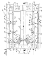
- a device 10 for sorting waste glass in particular waste hollow glass, shows a section 11 which serves for the treatment of large material 12, and only a hint of a section 13 which serves for the treatment of small material 14 and which is in detail 8-13.
- the large material 12 and the small material 14 are mainly represented symbolically only with an arrow, which at the same time specifies the transport direction.
- the device 10 is fed by means of a conventional conveyor, for example a conveyor belt 15, in the direction of the arrow (FIG. 2) with the material indicated by the arrow 16.
- the conveyor belt 15 can be preceded by at least one screening device, not shown, via which, for example, broken glass or the like is screened off from the mixture 16.
- two mutually parallel conveyor belts 15 are present. From these, the mix 16 is fed to a subsequent, suitably designed pre-separator 17, which separates the supplied mass flow into large material 12 on the one hand and small material 14 on the other.
- the small material 14 can, for example, first be fed to a receiving container 18 (FIG. 9) of the section 13 by means of a conveyor, or instead it is introduced directly into the section 13 by means of conveyor belts 19.
- the large material 12 sorted out by means of the pre-separator 17 arrives via an inclined transport track 20 in the form e.g. of a conveyor belt onto a conveyor track 21 which distributes the large material 12.
- This extends across the conveyor track 20 and can e.g. be designed as a vibratory conveyor.
- two mutually parallel and identical transport paths 22, 23 and 24, 25 are connected, each running parallel to one another.
- the transport tracks 22, 23 on the one hand and 24, 25 on the other hand are each of the same type and are arranged in mirror image to one another. They are each designed as vibratory conveyors. Further details are explained below in particular with reference to the transport track 23.
- a distribution track 26 and 27 which is also designed as a vibratory conveyor, and a distribution of the incoming large material flow 12 between the transport tracks 22 and 23 or 24 and 25 causes. This is indicated schematically by the arrows of the distribution path 26 and 27 directed towards them.
- the large material 12 transported forward on the transport path 23 in the transport direction has either already been occasionally fed by means of the distribution path 26 or is separated on the transport path 23.
- Each large piece of material 12 thus occupies its own place on the transport path 23 and lies there in such a way that no further part is located transversely to the transport direction, the next large pieces of material 12 being at a distance therefrom in the transport direction.
- the large piece of material 12 consists of a bottle, it is located 3 there is shown on the transport path 23 a bottle with a smaller diameter than the large material part 12 and on the transport path 22 with a larger diameter bottle as the large material part 12.
- Each transport track 22-25 is provided with individual stations 28, 29, 30 and 31 which are spaced apart from one another in the transport direction, as is indicated only schematically for the transport track 23.
- the large material 12 is occasionally moved on the transport tracks 22-25 past the individual stations 28, 29 and 30, with colored material of a particular color being separated from the mass flow and removed in each station.
- the structure and the order of the stations 28-30 are selected so that brown glass is first sorted out and removed from the mass flow of the large material 12 in the station 28, and is absolutely clean and colourfast, which is due to the corresponding structure and setting of the Station 28 is effected.
- the station 29 is designed in such a way that white glass is separated and discharged from the remaining and passed mass flow of the large material 12, here too, due to the design and setting of the station 29, great color fastness can be achieved and it is ensured that no ceramic parts in between and, depending on the setting, even the whitest white can be separated.
- the station 30 is used to select green glass and further mixed glass of other colors from the remaining mass flow of the large material 12, which has not previously been separated and removed in the stations 28 and 29.
- a transport track for example a conveyor belt, can be connected to this for the removal.
- the station 28 is thus constructed and set such that it only selects brown glass from the mass flow of the large material 12, and this is absolutely true to color and clean, with all other material parts of the mass flow passing through the station 28.
- the station 29 is constructed and set in such a way that white glass contained in the mass flow passed by is separated out absolutely cleanly and colourfast, all other constituents, including ceramic particles, refuse or the like, which are carried in the mass flow, pass through this station 29 without there to contaminate the discarded white glass.
- the station 30 is designed and set in such a way that green glass and mixed glass of other types of glass are selected from the remaining mass flow, the rest of the mass flow remaining thereafter, which mainly contains refuse, other opaque material or the like, in the station 31 of the receiving device 32 is received there.
- station 30 is constructed and set such that only green glass is selected by means of this and the remaining other mixed glass remains in the mass flow and then by means of a further, downstream one and the station, not shown, is removed and removed from the mass flow, whereupon in the station 31 only refuse and the like. Non-translucent material is collected and discharged. This means that it is also possible to convert to the selection of pure green glass in a simple manner.
- the transport tracks 21-25 and the distribution tracks 26 and 27, along which the large material 12 is moved, are each designed as vibratory conveyors. This is indicated schematically in FIG. 1 by the fact that a linear vibratory conveyor, which represents an oscillating drive, is shown in dashed lines below this transport path and is generally designated 33 for all transport paths.
- Each station 28, 29 and 30 is associated with a receiving device 34 or 35 or 36, in which the color material separated from the mass flow of the large material 12 is received, with similar recording devices which pick out separated glass material of the same color via not shown Transport devices, e.g. Conveyor belts are connected to one another, by means of which the glass material which is in each case separated out is fed to large containers which are not shown any further.
- Transport devices e.g. Conveyor belts are connected to one another, by means of which the glass material which is in each case separated out is fed to large containers which are not shown any further.
- the pre-separator 17 is designed in such a way that parts are sorted out as small material 14 whose diameter and / or edge length is less than about 5 cm to 7 cm, e.g. smaller than 5.5 cm.
- the transport track 23 has a channel defined by an angle plate with a bottom 37 and a wall 38, which can be at least slightly inclined with the bottom 37 out of the horizontal by raising the right side of the bottom 37 in FIG. 3, thereby ensuring that large material 12 transported along the transport path 23 is, if possible, forced into the corner region between the floor 37 and the wall 38 and, if possible, is guided and bears against both.
- At least the floor 37 - if desired also the wall 38 - is provided with a covering 39 which at least essentially has rigid bristles 40, for example made of plastic, which protrude and form a support for the large material 12.
- the bristles 40 of the coverings 39 are inclined in the direction of the desired transport direction, as can be seen in particular from FIGS. 5 and 6. The direction of transport is symbolized there by arrow 12 for the large material.
- Each station 28, 29 and 30 is provided with a recognition device 41 and associated ejector device 42, which is only illustrated for station 28 below with the aid of FIGS. 3-6 and by means of which the respective colored material can be selected from the mass flow of the large material 12, ie in the Station 28 brown glass.
- the detection device 41 of the station 28 is provided with a color detection device 43 and / or light barrier 44 which is only indicated schematically and which is superimposed here and combined to form a structural unit and is therefore only shown symbolically separated from one another and provided with different reference numerals.
- the color detection device 43 and the light barrier 44 are each provided with at least one transmitting device 43a or 44a and an associated receiving device 43b or 44b.
- the transmitting device 43a, 44a is arranged below the transport path 23 and the receiving device 43b, 44b at a distance above the transport path 23, the position and distance being selected such that the receiving device 43b, 44b does not interfere in this area.
- the transport path 23, namely both the floor 37 and the covering 39, is provided in the floor area which is hit by the detection beam 45 emanating from the transmitting device 43a, 44a, with an opening 46 which allows it to pass through and which is designed, for example, as an elongated hole .
- the transmitting device 43a, 44a and the associated receiving device 43b, 44b are together in one line of alignment aligned, which is predetermined by the course of the identified detection beam 45, the arrangement being such that this alignment line 45 is inclined to the right by an acute angle with respect to a vertical in FIG. 3 approximately perpendicular to the plane of the floor 37, for example is on the order of about 30 o .
- the detection beam 45 intersects the plane of the tips of the bristles 50 approximately one third of the total width of the base 37, measured from the corner on the left, to which the approximately vertical wall 38 adjoins.
- this alignment line of the transmitting device 43a, 44a and receiving device 43b, 44b predetermined by the detection beam 45 is inclined at an acute angle with respect to the vertical against the transport direction according to arrow 12 in FIG. 6, which is, for example, about 15 o Fig. 6 shows.
- the components of the color recognition device 43 and light barrier 44 are thus placed obliquely in the room. This prevents contamination and any specular reflections from a part that passes through station 28.
- the outgoing signal according to the identification beam 45 passes through the large material part 12 without any stray light and a false signal which may be caused thereby. This applies to the light barrier 44 as well as to the color recognition device 43. Both are illustrated in FIGS.
- the transmitting devices and the receiving devices of the color recognition device 43 and the light barrier 44 are each independent parts and placed separately. It is particularly advantageous if the respective transmitting device 43a and receiving device 43b of the color recognition device 43 are arranged separately and in a mirror image of the transmitting device 44a and receiving device 44b of the light barrier 44.
- the color detection device 43 is only indicated schematically with regard to the components described. It has sensors and is set in the station 28 so that the color recognition device 43 recognizes and selects brown glass from the mass flow of the large material 12 passing by, with great color fastness and as cleanly as such amber glass is required for recycling by industry .
- the light barrier 44 works e.g. in the infrared range. It can have glass fiber light guides. This is also set to the selection of brown glass in station 28.
- the other stations 29 and 30 are also equipped with corresponding detection devices, consisting of a color detection device and an associated light barrier, this determining the stations are constructed and adjusted accordingly so that white glass is selected in the station 29 color-fast and with great accuracy from the mass flow carried past and in the same way in the station 30 green glass and other translucent glass of other colors and types are selected from the remaining mass flow is selected.
- the ejector device 42 of the station 28 is explained in more detail below with reference to FIGS. 3 and 4.
- the ejector device 42 has individual ejector members 48 which are held on a carrier 47 at, for example, the same distance from each other and project from it and which strive approximately finger-like and are therefore also referred to below as ejector fingers.
- the carrier 47 here consists of a vertical circular disk carrying the radially directed ejector fingers 48 and is driven in rotation about a rotation axis 49, for example essentially parallel to the direction of transport according to arrow 12, by means of a drive 50, the drive being carried out batchwise and always in one direction, which points here in the counterclockwise direction according to arrow 51.
- the ejector fingers 48 are moved by the drive 50 in the arrow direction 51 transversely to the transport path 23 when the carrier 47 is actuated, the respective part currently in the station 28 and recognized by the detection device 41 as a material part 12 to be discarded transversely to the transport direction according to arrow 12 of FIG the transport path 23 is dropped. As shown, an ejector finger 48 is stored in its ready-to-eject starting position within an opening 52 of the laterally projecting wall 38.
- each ejector finger 48 and that of the opening 52 are matched to one another in such a way that an ejector finger 48 stored in the opening 52 in its ejecting starting position at least approximately fills the opening 52 and there forms a wall part practically completing the wall 38, so that large material 12 moved past it cannot get caught on it.
- Each ejector finger 48 has a thickness that approximately corresponds to the cross section of the wall 38 and a width that is preferably larger than the thickness, as shown in FIG. 4. Seen within the plane of the wall 38, each ejector finger 48 thus has an approximately plate shape. The width can also be chosen larger than shown.
- the ejector 42 of the station 28 and the components of the recognition device 41, in particular the color recognition device 43 and the light barrier 44, of this station are spatially arranged such that they do not interfere with one another, in particular the ejector 42 does not touch the receiving devices 43b and 44b.
- a wall 43 delimiting the transport path 23 there, which together with the floor 37 encloses an angle greater than 90 ° and is thus inclined from the bottom upwards and outwards.
- this wall 53 in the area of each station 28, 29 and 30 there is a delivery opening 54, the size of which is selected to be as large as the largest possible separated and to be discarded large material part 12. Since it can be assumed that lying and not broken bottles are also conveyed along as large material 12, the size of the discharge opening 54 measured in the transport direction is selected to be larger than the largest possible bottle size to be expected.
- the ejector fingers 48 are moved batchwise and in such a way that an ejector finger 48 stored in the opening 52 throws off the large material part 12 to be thrown in each case transversely to the direction of transport and at the same time a next ejector finger in the same direction according to arrow 51 is moved into its throw-ready starting position in the opening 52, as shown in FIG. 4.
- the ejector fingers are in the same way by means of a carrier along a straight path or another arc-shaped path deviating from a circular arc path moved in batches.
- the path can be chosen, for example, following an ellipse section, a parabola section or another curve section.
- a modified embodiment of an ejector 42 ' is shown schematically, in which the carrier 47' or the like as a double-deflected chain, belt, band. Endless element is formed on which the projecting individual ejector fingers 48 'are held.
- the carrier 47 'designed in this way in the form of a chain is guided at both deflecting ends via a sprocket 55, 56, of which the latter is driven in batches by means of a drive 50' in the direction of the arrow 51 'when the assigned detection device generates a drive pulse on the drive 50 'there.
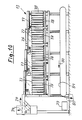
- the small material symbolized by arrow 14 is first fed, for example, by means of conveyor belts 19 and deflected via a distribution track 57 designed as a vibrating conveyor device and fed to a linear vibrating conveyor device 58.
- a long side of the linear vibratory conveyor 58 is followed by a plurality of individual obliquely downwardly directed vibratory conveyors 59 which have individual conveyor troughs 60, a plurality of oblique vibratory conveyor devices 59 each being combined to form a plate which has, for example, seven conveyor troughs 60.
- the small material 14 brought in is conveyed and separated in the longitudinal direction by means of the linear vibratory conveyor 58 and - as indicated by right-angled arrows 61 - from there distributed to the individual connected, obliquely downwardly directed vibratory conveyors 59 with individual conveyor troughs 60 and down to the bottom End of each individual conveyor trough 60 transported.
- the small material 14 is also isolated in this way.
- Each conveyor trough 60 directed obliquely downwards forms a transport path which, in the same way as the transport paths 21-25 and distribution paths 26 and 27, on the floor 37 and also on the wall 38, which is approximately angled on one side, with a covering 39 with projecting bristles 40 are provided, as indicated only in FIGS. 11-13 and in FIG. 9 on the right.
- FIG. 11 shows that the bristles 40 of the coating 39 in Fig. 11 are directed obliquely at the top in the transport direction according to arrow 61, so that the small material 14 is guided in the arrow direction 61 onto the conveyor troughs 60, and that the remaining part of the bristles 40 in Direction of the longitudinal course of the linear vibratory conveyor 58 is directed so that these bristles 40 transported small material 14 in the longitudinal direction.
- This is illustrated in FIG. 12, where this longitudinal transport direction is marked with arrow 14 for the small material.
- FIG. 9 shows on the right a single conveyor trough 60 which, in accordance with the section in FIG. 13, is provided with an illustrated covering 39 in the region of the bottom 37 and the wall 38.
- a detection device 41 is provided for this conveyor trough 60, which here only consists of a light barrier 44, which has a transmitting device 44a and a receiving device 44b.
- the transmitting device 44a and receiving device 44b of the light barrier 44 is inclined in the same way as shown in FIG. 6 in the transport direction of the small material 14 in relation to the line running at right angles to the floor 37 in the transport direction by an acute angle, which can be, for example, in the order of 15 o .
- the detection beam 45 which emanates from the transmitting device 44a and is directed towards the receiving device 44b, is therefore not at right angles to the floor 37, but instead runs obliquely in the transport direction. If necessary, everyone is at the bottom Conveyor trough 60 placed several such light barriers 44 next to one another transversely to the transport direction, which practically form a light barrier curtain.
- a deflection flap 63 is arranged for each conveyor trough 60 and is pivotable about an approximately horizontal axis 62 and can be actuated by a drive in the form of a pneumatic cylinder 64 as a function of a pulse supplied by the detection device 41 .
- the deflector flap 63 together with its associated pneumatic cylinder 64 and the detection device 41 are held by means of a holding device 65 and adjustable in height. In the approximately vertical position shown in solid lines in FIG.
- the deflector flap 63 is in its starting position, which the deflector flap 63 then assumes and maintains when no pulse acting on the pneumatic cylinder 64 comes from the detection device 41, ie when the light barrier 44 is not interrupted. If, on the other hand, the light barrier 44 is interrupted, it actuates the pneumatic cylinder 64, which swivels the deflection flap 63 in the direction of the arrow 66 about the axis 62 in the counterclockwise direction forward into the position indicated by dashed lines. In this rejection position, the deflection flap 63 is able to reject small material 14 located at the end of the conveyor trough 60, which consists of refuse or the like.
- Opaque material and has caused the light barrier 44 to be interrupted, in the direction of the dashed arrow 67 and into an associated one to guide the underlying receptacle 68 into which this material falls.
- the receptacle 68 can be common to several conveyor lines 60 or can run over all conveyor lines 60 and can be connected to a conveyor track 69, e.g. B. a conveyor belt, in connection via which the opaque material selected in this way is transported away in the direction of arrow 70.
- the deflector flap 63 Immediately after pivoting the deflector flap 63 into the dashed deflection position, the deflector flap 63 is activated by means of the pneumatic cylinder 64 Returned to the vertical starting position, in which the deflector flap 63 in turn remains until an actuation pulse is again exerted by the pneumatic cylinder 64 when the light barrier 44 breaks through opaque material. In the vertical starting position of the deflector flap 63, this is either ineffective or at least only so effective that small material 14 discharged at the lower end of the conveyor trough 60 in the direction of arrow 71 either first into a receptacle 72 or immediately onto a transport path 73, for. B. is given in the form of a conveyor belt.
- the receptacle 72 and in particular the transport path 73 extends along the lower ends of all inclined conveying troughs 60 and is common to them, so that the conveying path 73 receives all of the small material of the conveying troughs 60 which are opaque during the selection and removal of debris or the like is left.
- the mixing glass 74 is transported away via the transport path 73 leading obliquely from bottom to top and fed to a linear vibratory conveyor device 76 via a distribution path 75.
- the distribution path 75 and linear vibratory conveyor 76 is constructed analogously to those 57 and 58, respectively.
- each conveyor trough 78 the transported and separated mixed glass 74 is selected for white glass 79 on the one hand and a mixture 80 of green glass and amber glass on the other hand, each for both Weil assigned receptacles 81 and 82 may be provided or instead the white glass 79 or the mixture 80 of green and amber glass directly onto assigned transport tracks 83 and 84, z. B. conveyor belts, is routed through which the derivation takes place.
- the device 10 is used to select the large material 12 in the area of the respective recognition device 41 by superimposing the respective color recognition devices 43 on the one hand and light barriers 44 on the other hand.
- Colored material in particular in the order of the colors brown, white and green, is selected from the large material 12 in the stations 28 or 29 or 30 and only then, at the end, as a remaining part of the mass flow of the large material 12 remaining debris and the like.
- Non-translucent parts are collected in the area of the station 31 and the receiving device 32 there or are immediately removed by means of a conveyor belt. In this way it is achieved that first in the station 28 absolutely clean and colourfast brown glass is separated from the mass flow of the large material 12 and transported away, in the colourfastness and quality required by the industry.
- the detection devices 41 are designed in such a way that their analog or digital outputs each provide easily evaluable signals in relation to the type of material to be sorted, so that reliable output signals are always generated. Since the ejector 42 works with the ejector fingers 48 per station 28, 29 and 30 so that in the selection per station 28, 29 and 30 the ejection takes place in one direction, namely the drive direction according to arrows 51 and 51 ', the movement of the ejector finger 48 in their ejection-ready starting position in the same direction according to arrow 51 or 51 ', there is no opposite return movement in the starting position, which could otherwise delay or hinder the further transport of the large material 12 in the transport direction.
- each ejector finger 48 is ge in the ready position for ejection outside the area of the respective transport path 23 brings. Since each ejector finger 48 is in this position approximately congruent with the wall 38 and thus close to the respective large material 12 passing through the station 28, 29 or 30, the ejection path for the ejector finger 48 to be traversed in the event of an ejection to be carried out is extremely small. This enables short cycle times for the batch-wise movement of the ejector device 42.
- each ejector finger 48 viewed in the direction of transport, is approximately plate-shaped and thus of substantial width, then the safety is increased even in the direction of transport of the smallest large pieces of material 12 then across this by means of this ejector finger 48 Eject the transport direction through the discharge opening 54 if, when passing through the detection device 41, a corresponding impulse is passed from it to the drive 50 of the ejector device 42 and the ejector device is thereby advanced by one step in the drive direction 51.
- the fact that the individual components of the color recognition device 43 and light barrier 44 of each individual recognition device 41 present for each station 28, 29 and 30 are arranged obliquely in space in the manner described, prevents any scattered rays and the resulting false signals. Rather, it is ensured that the detection device 41 detects each individual material part with great accuracy and sorts it out via the assigned ejector device 42, which is actually to be detected per station 28, 29 and 30 and setting.
- the small material 14 is selected by means of the section 13, selection is first made in stages according to mixed glass 74 on the one hand and rubbish and the like opaque material on the other hand. In a next stage, the mixed glass is then selected according to white glass 79 on the one hand and a mixture 80 of green and amber glass and glass having other colors on the other hand. If this is desired, a further selection of the mixture 80 according to amber glass on the one hand and glass containing green glass and other colors can be selected in a further, appropriately designed stage on the part of.
- the respective small material 14 is detected at the end of the individual sloping feed channels 60 and 78 by means of light barriers 44 there, at least one per feed channel 60 and 78, at the moment when the small material 14 is still at least partially rests on the transport path of the conveyor trough 60 or 78 and already protrudes freely therefrom with a part that has passed through the detection beam 45, so that this material part can be passed through the detection beam 45.
- This ensures a high level of accuracy in the detection and selection of the small material 14, so that ultimately, with extremely high accuracy, selection of white glass 79 on the one hand and a mixture 80 consisting of green glass, amber glass and other colors containing glass, on the other hand, is possible and any debris or the like. Opaque parts thereof can be split off from the outset in the first selection stage.
- the device 10 has a modular structure with regard to its individual components, as a result of which throughput quantities and the system design can be put together variably as desired.
Landscapes
- Health & Medical Sciences (AREA)
- General Health & Medical Sciences (AREA)
- Toxicology (AREA)
- Sorting Of Articles (AREA)
Applications Claiming Priority (2)
| Application Number | Priority Date | Filing Date | Title |
|---|---|---|---|
| DE19883817026 DE3817026A1 (de) | 1988-05-19 | 1988-05-19 | Verfahren und einrichtung zum sortieren von altglas |
| DE3817026 | 1988-05-19 |
Publications (2)
| Publication Number | Publication Date |
|---|---|
| EP0342389A2 true EP0342389A2 (fr) | 1989-11-23 |
| EP0342389A3 EP0342389A3 (fr) | 1992-08-12 |
Family
ID=6354673
Family Applications (1)
| Application Number | Title | Priority Date | Filing Date |
|---|---|---|---|
| EP19890107361 Withdrawn EP0342389A3 (fr) | 1988-05-19 | 1989-04-24 | Procédé et dispositif de tri de verre récupéré |
Country Status (2)
| Country | Link |
|---|---|
| EP (1) | EP0342389A3 (fr) |
| DE (1) | DE3817026A1 (fr) |
Cited By (5)
| Publication number | Priority date | Publication date | Assignee | Title |
|---|---|---|---|---|
| US5333797A (en) * | 1992-04-03 | 1994-08-02 | Becker John C | Commingled recyclables recovery and recycling process and related apparatuses |
| US5333739A (en) * | 1992-03-27 | 1994-08-02 | Bodenseewerk Geratechnik GmbH | Method and apparatus for sorting bulk material |
| US5344025A (en) * | 1991-04-24 | 1994-09-06 | Griffin & Company | Commingled waste separation apparatus and methods |
| GB2283812A (en) * | 1993-11-10 | 1995-05-17 | Kanetsu Engineering Co Ltd | Automatic colour sorting apparatus and method for sorting and recovering cullets |
| NL1006555C2 (nl) * | 1997-07-11 | 1999-01-12 | Con Weigh Beheer B V | Inrichting bestemd voor het inspecteren, sorteren en/of doseren van chaotisch geordende voorwerpen. |
Families Citing this family (3)
| Publication number | Priority date | Publication date | Assignee | Title |
|---|---|---|---|---|
| DE9106292U1 (de) * | 1991-05-22 | 1991-07-18 | Glasrecycling Leeseringen GmbH & Co. KG, 3071 Estorf | Vorrichtung zum Sortieren von Altmaterial, insbesondere Altglas nach seiner Farbe |
| DE4200226A1 (de) * | 1992-01-08 | 1993-07-15 | Josef Kamps | Maschine zum erkennen von farbunterschieden an einzelnen fraktionen von schnittguetern und gleichzeitiger fraktionierung |
| DE9413671U1 (de) * | 1994-08-25 | 1994-11-24 | Zill, Tobias, 73110 Hattenhofen | Sortieranlage zur Farbsortierung von Glas, vorzugsweise Altglas |
Family Cites Families (6)
| Publication number | Priority date | Publication date | Assignee | Title |
|---|---|---|---|---|
| US3980180A (en) * | 1974-11-20 | 1976-09-14 | Jamieson John A | Transmissive article sorting apparatus |
| DE3119329C2 (de) * | 1981-05-15 | 1983-03-31 | Gerresheimer Glas AG, 4000 Düsseldorf | Vorrichtung zur Farbsortierung von Althohlglas |
| DE3207447C2 (de) * | 1982-03-02 | 1983-12-29 | Fraunhofer-Gesellschaft zur Förderung der angewandten Forschung e.V., 8000 München | Verfahren und Einrichtung zur Erkennung und Separierung von Glasscherben nach optischen Eigenschaften |
| FR2544856B1 (fr) * | 1983-04-25 | 1986-10-24 | Oreal | Procede de controle de l'epaisseur des parois de recipients en verre et dispositif correspondant |
| DE3346129C2 (de) * | 1983-12-21 | 1986-09-18 | Fa. Hermann Heye, 3063 Obernkirchen | Vorrichtung zum Sortieren von Altglas enthaltendem Abfall |
| DE3445428A1 (de) * | 1984-12-13 | 1986-06-19 | MAB Marlis Kellermann, 7521 Dettenheim | Glas-sortieranlage |
-
1988
- 1988-05-19 DE DE19883817026 patent/DE3817026A1/de not_active Withdrawn
-
1989
- 1989-04-24 EP EP19890107361 patent/EP0342389A3/fr not_active Withdrawn
Cited By (6)
| Publication number | Priority date | Publication date | Assignee | Title |
|---|---|---|---|---|
| US5344025A (en) * | 1991-04-24 | 1994-09-06 | Griffin & Company | Commingled waste separation apparatus and methods |
| US5333739A (en) * | 1992-03-27 | 1994-08-02 | Bodenseewerk Geratechnik GmbH | Method and apparatus for sorting bulk material |
| US5333797A (en) * | 1992-04-03 | 1994-08-02 | Becker John C | Commingled recyclables recovery and recycling process and related apparatuses |
| GB2283812A (en) * | 1993-11-10 | 1995-05-17 | Kanetsu Engineering Co Ltd | Automatic colour sorting apparatus and method for sorting and recovering cullets |
| NL1006555C2 (nl) * | 1997-07-11 | 1999-01-12 | Con Weigh Beheer B V | Inrichting bestemd voor het inspecteren, sorteren en/of doseren van chaotisch geordende voorwerpen. |
| WO1999002279A1 (fr) * | 1997-07-11 | 1999-01-21 | Con-Weigh Beheer B.V. | Dispositif d'inspection, de triage et/ou de quantification d'objets en ordre anarchique |
Also Published As
| Publication number | Publication date |
|---|---|
| EP0342389A3 (fr) | 1992-08-12 |
| DE3817026A1 (de) | 1989-11-23 |
Similar Documents
| Publication | Publication Date | Title |
|---|---|---|
| EP0669171B1 (fr) | Dispositif de tri de déchets | |
| EP0666115A2 (fr) | Procédé de tri de particules en vrac et dispositif à cet effet | |
| EP0982083B1 (fr) | Dispositif linéaire de tri | |
| EP0029614B1 (fr) | Dispositif pour la déviation latérale d'objets d'un premièr sur un second dispositif de transport | |
| DE69520809T2 (de) | Sortiervorrichtung für Bohnen | |
| DE3612076A1 (de) | Vorrichtung und anlage zum optischen sichten von unreinem glasbruch | |
| CH643160A5 (de) | Vorrichtung zum klassieren von teilchen mit unterschiedlicher farbgebung. | |
| EP0636322B1 (fr) | Dispositif de transport pour la formation d'une couche uniforme | |
| DE69617696T2 (de) | Vorrichtung und verfahren zur inspektion und sortierung von artikeln | |
| DE69700944T2 (de) | Rutsche für Sortiereinrichtung | |
| DE3614400C1 (de) | Verfahren und Vorrichtung zum Steuern einer Farbsortiermaschine | |
| DE69313313T2 (de) | Anordnung zum Sortieren von Artikeln | |
| EP0342389A2 (fr) | Procédé et dispositif de tri de verre récupéré | |
| DE3828067C2 (fr) | ||
| EP0461616B1 (fr) | Procédé et dispositif de tri de déchets de verre | |
| DE19545240A1 (de) | Verfahren und Vorrichtung zum Trennen von Materialgemischen nach der Sorte | |
| DE19646753C2 (de) | Einrichtung zur Qualitäts- und/oder Größensortierung kleinstückiger Produkte | |
| EP0805771A1 (fr) | Dispositif pour selectionner un ou plusieurs contenants a symetrie de rotation dans un flux de tels contenants transportes sous l'effet d'une pression dynamique et verin avec piston a deplacement commande | |
| DE3914360C2 (fr) | ||
| DE9106292U1 (de) | Vorrichtung zum Sortieren von Altmaterial, insbesondere Altglas nach seiner Farbe | |
| DE10123304A1 (de) | Vorrichtung und Verfahren zur Sortierung eines Abfallgemisches | |
| EP0565038A1 (fr) | Procédé et dispositif pour le tri de déchets | |
| DE8904443U1 (de) | Einrichtung zum Sortieren von Altglas | |
| DE3935334A1 (de) | Verfahren und vorrichtung zum sortieren von altglas, insbesondere flaschen | |
| AT402165B (de) | Verfahren und vorrichtung zum sortieren von abfällen |
Legal Events
| Date | Code | Title | Description |
|---|---|---|---|
| PUAI | Public reference made under article 153(3) epc to a published international application that has entered the european phase |
Free format text: ORIGINAL CODE: 0009012 |
|
| AK | Designated contracting states |
Kind code of ref document: A2 Designated state(s): AT BE CH DE ES FR GB GR IT LI LU NL SE |
|
| PUAL | Search report despatched |
Free format text: ORIGINAL CODE: 0009013 |
|
| AK | Designated contracting states |
Kind code of ref document: A3 Designated state(s): AT BE CH DE ES FR GB GR IT LI LU NL SE |
|
| 17P | Request for examination filed |
Effective date: 19930105 |
|
| RAP3 | Party data changed (applicant data changed or rights of an application transferred) |
Owner name: MIGL, HORST Owner name: HECHT, DIETER Owner name: KOPPELBERG, HELMUT Owner name: SCHWARZ, HANS-MICHAEL |
|
| 17Q | First examination report despatched |
Effective date: 19940719 |
|
| STAA | Information on the status of an ep patent application or granted ep patent |
Free format text: STATUS: THE APPLICATION IS DEEMED TO BE WITHDRAWN |
|
| 18D | Application deemed to be withdrawn |
Effective date: 19941130 |