EP0666451A1 - Générateur de vapeur - Google Patents
Générateur de vapeur Download PDFInfo
- Publication number
- EP0666451A1 EP0666451A1 EP95810067A EP95810067A EP0666451A1 EP 0666451 A1 EP0666451 A1 EP 0666451A1 EP 95810067 A EP95810067 A EP 95810067A EP 95810067 A EP95810067 A EP 95810067A EP 0666451 A1 EP0666451 A1 EP 0666451A1
- Authority
- EP
- European Patent Office
- Prior art keywords
- steam
- steam chamber
- water
- impeller
- vanes
- Prior art date
- Legal status (The legal status is an assumption and is not a legal conclusion. Google has not performed a legal analysis and makes no representation as to the accuracy of the status listed.)
- Granted
Links
- XLYOFNOQVPJJNP-UHFFFAOYSA-N water Substances O XLYOFNOQVPJJNP-UHFFFAOYSA-N 0.000 claims abstract description 47
- 238000010438 heat treatment Methods 0.000 claims abstract description 22
- XEEYBQQBJWHFJM-UHFFFAOYSA-N Iron Chemical compound [Fe] XEEYBQQBJWHFJM-UHFFFAOYSA-N 0.000 claims description 18
- 229910052742 iron Inorganic materials 0.000 claims description 9
- 238000010409 ironing Methods 0.000 claims description 3
- 238000002347 injection Methods 0.000 claims description 2
- 239000007924 injection Substances 0.000 claims description 2
- 210000000056 organ Anatomy 0.000 claims 1
- 238000009987 spinning Methods 0.000 claims 1
- 229920003023 plastic Polymers 0.000 description 8
- 239000004020 conductor Substances 0.000 description 7
- XAGFODPZIPBFFR-UHFFFAOYSA-N aluminium Chemical compound [Al] XAGFODPZIPBFFR-UHFFFAOYSA-N 0.000 description 6
- 229910052782 aluminium Inorganic materials 0.000 description 6
- 230000008878 coupling Effects 0.000 description 5
- 238000010168 coupling process Methods 0.000 description 5
- 238000005859 coupling reaction Methods 0.000 description 5
- 230000008901 benefit Effects 0.000 description 3
- 230000033001 locomotion Effects 0.000 description 3
- 239000000463 material Substances 0.000 description 2
- 230000007246 mechanism Effects 0.000 description 2
- 210000002445 nipple Anatomy 0.000 description 2
- 239000000843 powder Substances 0.000 description 2
- 238000007789 sealing Methods 0.000 description 2
- 235000008733 Citrus aurantifolia Nutrition 0.000 description 1
- 229910000831 Steel Inorganic materials 0.000 description 1
- 235000011941 Tilia x europaea Nutrition 0.000 description 1
- 230000001133 acceleration Effects 0.000 description 1
- 238000005119 centrifugation Methods 0.000 description 1
- 238000004140 cleaning Methods 0.000 description 1
- 230000001419 dependent effect Effects 0.000 description 1
- 238000001704 evaporation Methods 0.000 description 1
- 230000008020 evaporation Effects 0.000 description 1
- 229920002457 flexible plastic Polymers 0.000 description 1
- 230000010006 flight Effects 0.000 description 1
- 238000009413 insulation Methods 0.000 description 1
- 239000004571 lime Substances 0.000 description 1
- 229920001296 polysiloxane Polymers 0.000 description 1
- 238000005086 pumping Methods 0.000 description 1
- 125000006850 spacer group Chemical group 0.000 description 1
- 238000013020 steam cleaning Methods 0.000 description 1
- 239000010959 steel Substances 0.000 description 1
- 230000007704 transition Effects 0.000 description 1
- 238000009692 water atomization Methods 0.000 description 1
Images


Classifications
-
- F—MECHANICAL ENGINEERING; LIGHTING; HEATING; WEAPONS; BLASTING
- F22—STEAM GENERATION
- F22B—METHODS OF STEAM GENERATION; STEAM BOILERS
- F22B1/00—Methods of steam generation characterised by form of heating method
- F22B1/28—Methods of steam generation characterised by form of heating method in boilers heated electrically
- F22B1/287—Methods of steam generation characterised by form of heating method in boilers heated electrically with water in sprays or in films
Definitions
- the present invention relates to a device for generating steam according to the preamble of claim 1 and to an arrangement with a device for generating steam for an iron.
- An advantage of the device according to the invention is that it can be operated in any position.
- the first exemplary embodiment of the device 1 for steam generation according to FIG. 1 has a rotationally symmetrical body 2.
- the outside of the rotationally symmetrical body 2 comprises two adjoining heating shells 3 and 4, the inner walls 5 and 6 of which delimit an annular steam chamber 7.
- a seal 9 made of temperature-resistant material, for example silicone, is arranged between the radiator 8 and the steam chamber 7.
- the two heating dishes are made of a good heat-conducting material, e.g. aluminum.
- An upper part 10 of the rotationally symmetrical body 2 made of poorly heat-conducting material, for example of heat-resistant plastic, adjoins the upper heating shell 3 according to FIG. 1.
- a lower part 11 is also connected to the lower heating bowl 4 according to FIG. 1 from poorly heat-conducting material, for example from heat-resistant plastic.
- the two heating shells 3 and 4 as well as the upper part 10 and the lower part 11 enclose the annular steam chamber 7.
- the cross section of the steam chamber can be circular, elliptical, oval or egg-shaped, for example.
- the heating shells 3 and 4 made of good heat-conducting material, namely aluminum, conduct the heat from the radiator 8 to the wall 5, 6 of the steam chamber 7.
- the rotationally symmetrical body 2 is held together by steel rings 12 and 13.
- An electric motor 15 attached to a flange 14 drives an impeller 17 reaching into the steam chamber 7 via an axis 16.
- the axis 16 is supported in bearings 18 and 19 at the bottom and top of the lower part 11.
- the electric motor 15 drives the piston rod 21 of a piston pump 22 via a crank mechanism 20.
- the pump 22 pumps water from a water tank 23 via a first line 24 and a first valve 25 via a second valve 26 and a second line 27 to a connecting piece 28 on the upper part 10 of the device for generating steam.
- the water passes through a channel 29 in the connecting piece 28 via channels 30 to the center of the rotating impeller 17 and to the blades 32 of the impeller.
- the centrifugal force throws the water into tiny drops atomized outwards onto the hot steam chamber wall 5, 6, where they evaporate.
- the impeller 17 (fan wheel) generates a turbulent air movement in the heated steam chamber 7 by rotation.
- the additional air flow in the steam chamber increases the even distribution of the water on the hot chamber wall and results in an optimal use of the available thermal energy and the generation of a maximum amount of steam.
- the steam is through the space 31, two bores 33 and 34 and a coupling piece 35 via a connecting line 36 to the consumer, for example an iron.
- a plastic part 37 prevents steam from flowing into the area of the end of the axis 16. Steam is supplied through two bores 38 and 39 via a connecting piece 40 and a line 41, for example a manometer 42 or a second consumer.
- the plastic part 37 also prevents steam from flowing into the region of the end of the axis 16 in this steam supply line.
- a thermostat can be used in a recess 43 and is fastened with a fastening screw 44.
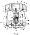
- the second exemplary embodiment of the device 45 for steam generation according to FIG. 2 is likewise designed to be rotationally symmetrical. It comprises a lower part 46, as shown in FIG. 2, made of a material which is a good heat conductor, for example aluminum, with an annular recess 47. A central part 48 adjoins this and is connected to the lower part 46. The middle part 48 also consists of a good heat-conducting material, for example aluminum. A cover 49 with an attachment piece 50 connected to it is placed on the middle part 48 by means of a bayonet lock 51. The cover 49 is made of plastic and the extension piece 50 is made of poorly heat-conducting material, for example of heat-resistant plastic. The attachment piece 50 is fastened to bolts 52 which are designed to be integrated with the cover 49.
- An O-ring 53 is arranged on the outer circumference of the extension piece 50 and seals the extension piece 50 with respect to the central part 48.
- parts 54 and 55 are formed on the intermediate piece 50, for example in the form of a half hollow cylinder for holding a water supply hose 56, which form a kind of "labyrinth".
- the water hose 56 is connected to a connecting piece 57, which in a bore 58 in Extension piece 50 is inserted.
- a heater 60 provided with a casing 59 is pressed into the bottom of the lower part 46.
- the casing 59 is preferably made of aluminum.
- a conventional radiator available on the market is used as the radiator 60.
- axle bearing piece 65 for mounting an axis of rotation 66 is embedded in a central opening 64 in this annular extension 63.
- the axle bearing piece 65 has two bearings 67 and 68 for mounting the axle 66.
- the axle bearing piece is sealed with an O-ring 69 in the annular extension part 63.
- a sealing cap 70, preferably made of plastic, is placed on the axle bearing piece 65.
- An impeller 71 with a central part 72 and four vanes 73 fastened thereon is placed on the axis 66.
- the axis 66 is inserted into a bore 75 arranged in a central projection 74 of the central part 72.
- the axis 66 is driven by a motor in the same way as in the exemplary embodiment according to FIG. 1 via a crank mechanism.
- the motor also drives a piston pump which conveys water from a flexible water tank to the water supply hose 56.
- the water conveyed through the hose 56 reaches the center of the disk-shaped central part 72 of the impeller 71 via the connecting piece 57 and the bore 58, the rotating central part 72 atomizing the water in tiny drops and throwing it outwards onto the hot steam chamber wall 76.
- the inner surfaces of the lower part 46, the middle part 48 and the extension piece 50 form the steam chamber 77 which is oval in cross section. Only the inner walls of the lower part 46 and of the central part 48, which are preferably made of aluminum, heated.
- the inner surfaces of the extension piece 50 made of plastic are not or only moderately heated.
- four water injection channels 78 are arranged at right angles to one another.
- the vanes 73 of the impeller 71 cause turbulent air movement in the heated steam chamber 77.
- the additional air flow in the steam chamber reinforces the even distribution of the water on the hot chamber wall and optimally utilizes the available thermal energy and generates a maximum Amount of steam.
- the steam is supplied via the steam outlet ring 61 and a channel 79 to a coupling piece 80 and via a hose 81 to the consumer, for example an iron.
- a second coupling piece 82 can also be provided, with steam being supplied to it from the steam outlet ring 61 via a channel 83.
- the steam is passed from the coupling piece 82 via a line 84 to a pressure gauge (not shown) or other consumers.
- a temperature sensor 85 can also be provided on the lower surface of the lower part 46 according to FIG. 2.
- the impeller which is located only a small distance 89 from the lower end of the extension piece 50, fulfills two functions, namely the centrifugation of the water drops with the disk-shaped surface 87 of the central part 72, which acts as a centrifugal surface, and the acceleration of the air with the flights 73.
- the drive shaft 66 for the impeller 71 is connected to the drive shaft of the motor, not shown, for example via a coupling piece 86.
- a flexible plastic container is preferably used as the water tank (not shown). This has the advantage that the water tank in every position is functional, since the atmospheric pressure compresses it so that water can always be drawn off, which is not the case with the rigid container, for example if it is upside down.
- the device for generating steam should be designed to be portable and can be used in any position. The device can be controlled by pumping more or less water according to the voltage and rotating the impeller faster or slower. Heat can be stored on the heated steam chamber wall 76, so that a lot of steam can be drawn for a short time. The heat energy can be extracted very quickly by the device with the impeller. In a pressure boiler system, the temperature or the pressure would be increased to the extent that this would be critical to the system.
- the steam is drawn in impulses, but not under the increased pressure that would be necessary in a conventional steam boiler.
- water is supplied almost under atmospheric pressure, the heat in the housing 3, 4; 46, 48 is stored.
- a fixed water connection with a pressure reducing valve could also be provided, which would also make it possible to use the device for generating steam in any position.
- the water connection could be opened or. getting closed.
- the second embodiment has the advantage of the removable cover over the first, which facilitates limescale removal.
- the device for generating steam can be opened immediately after use, since there is no excess pressure.
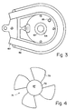
- FIG. 3 shows a bottom view of the heating device.
- FIG. 4 shows the impeller, with the middle part provided with a flat or structured centrifugal surface 87 and the four vanes 73 adjoining it. Fewer or more vanes could also be provided.
- the device comprises a heating element 91 and a steam chamber head 92.
- a heating spiral 93 is arranged in the heating element 91.
- the heating element 91 has a protruding hollow cylindrical edge 94 which is provided with a thread 95 on the outside.
- the heating element 91 is screwed into the steam chamber head with the hollow cylindrical edge 94.
- a seal 96 is arranged between the heating element 91 and the steam chamber head 92.
- the heater 91 and the steam chamber head 92 form the housing for the steam chamber.
- the inner wall 97 (steam chamber wall) of the heating element 91 and the inner wall 98 (steam chamber wall) of the steam chamber head form an annular steam chamber 99.
- An impeller 100 is arranged in the steam chamber as a rotating member.
- the impeller 100 has, for example, five blades 101 and a central part 102.
- the wings 101 are approximately semicircular.
- the impeller 100 is driven via an axle extension 103, which engages in a hub 104, by a motor 105 with an axle 106.
- the axle extension 103 is supported by an axle support bearing 107.
- An axis sealing device 108 is also provided.
- the engine is arranged with a motor spacer sleeve 109 in the steam chamber head 92.
- Via a water connection 110 water in the area of the wings 101 is passed through a bore 111 in the steam chamber head 92 of the steam chamber fed.
- the water connection can be connected to a pump and this to a water tank.
- the bore 111 serves as a water supply line.
- the water is atomized into tiny drops by the rapidly rotating impeller and reaches the hot steam chamber wall 97, 98 where the water drops evaporate.
- the water drops rotate around the center line of the steam chamber as well as around the drive axis and its intended extension for the impeller. This ensures good mixing of the water droplets and enables rapid evaporation, ie a lot of steam can reach the consumer in a short time.
- the steam passes through two bores 112 and 113 in the area of the vanes 101, which are arranged opposite the inlet bore 111 for the water with respect to the axis 103, 106, and to a steam connection nipple 114 and through a hose (not shown) connected to this connection nipple to the end user.
- the bores 111, 112, 113 are arranged in the wider end with respect to the cross section of the steam chamber 99.
- an overpressure control device 115 with a spring 116 and a valve cone 117 is provided.
- a holding plate 118 is connected to a junction box 119 for a steam connector, not shown. This junction box 119 is provided with a hinged cover 120.
- a double-walled heat insulation 121 is provided over the radiator 91.
- the annular steam chamber 99 has an approximately egg-shaped cross section. This could also be circular, elliptical or oval, for example.
- the arrows indicate the direction of movement of the water droplets respectively the steam specified.
- the curved central part 102 of the impeller 100 divides the vanes 101 into a part 122 close to the axis and into a part 123 remote from the axis.
- the hub 104 of the impeller lies on the conical central part 124 of the central part 125 of the heating element 91.
- a gap is formed between the end face of the central part 125 of the heating element 91 and the end region 126 of the impeller 100, through which steam flows from the part 128 of the steam chamber 99 facing away from the impeller 100 into the part 122 of the impeller near the axis.
- the limescale deposits occur largely in powder form thanks to water atomization by air flow and centrifugal force, which makes cleaning easier.
- Steam generation is possible in any position with the device according to the invention, which facilitates portable operation.
- the device can also be used for steam cleaning, for example, whereby the device for steam generation can be moved around.
- the amount of steam can be steplessly controlled from the implement (iron / steam cleaner, etc.).
- the device for steam generation can i.a. can be used for an iron.
- the device is preferably arranged in the region of the ironing board, a steam delivery line being connected to the iron.
Landscapes
- Engineering & Computer Science (AREA)
- Life Sciences & Earth Sciences (AREA)
- Sustainable Development (AREA)
- Sustainable Energy (AREA)
- Physics & Mathematics (AREA)
- Thermal Sciences (AREA)
- Mechanical Engineering (AREA)
- General Engineering & Computer Science (AREA)
- Irons (AREA)
- Engine Equipment That Uses Special Cycles (AREA)
Applications Claiming Priority (2)
| Application Number | Priority Date | Filing Date | Title |
|---|---|---|---|
| CH32294 | 1994-02-04 | ||
| CH322/94 | 1994-02-04 |
Publications (2)
| Publication Number | Publication Date |
|---|---|
| EP0666451A1 true EP0666451A1 (fr) | 1995-08-09 |
| EP0666451B1 EP0666451B1 (fr) | 1998-10-21 |
Family
ID=4184381
Family Applications (1)
| Application Number | Title | Priority Date | Filing Date |
|---|---|---|---|
| EP95810067A Expired - Lifetime EP0666451B1 (fr) | 1994-02-04 | 1995-02-02 | Générateur de vapeur |
Country Status (5)
| Country | Link |
|---|---|
| US (1) | US5581919A (fr) |
| EP (1) | EP0666451B1 (fr) |
| JP (1) | JPH0835605A (fr) |
| AT (1) | ATE172525T1 (fr) |
| DE (1) | DE59503962D1 (fr) |
Cited By (2)
| Publication number | Priority date | Publication date | Assignee | Title |
|---|---|---|---|---|
| WO2004061367A1 (fr) * | 2003-01-03 | 2004-07-22 | LACERTA S.r.L. CON UNICO SOCIO | Chaudiere pour la production de vapeur |
| CN105229219A (zh) * | 2013-07-25 | 2016-01-06 | 皇家飞利浦有限公司 | 用于产生蒸汽的装置 |
Families Citing this family (7)
| Publication number | Priority date | Publication date | Assignee | Title |
|---|---|---|---|---|
| US6336454B1 (en) | 1997-05-16 | 2002-01-08 | Resmed Limited | Nasal ventilation as a treatment for stroke |
| US6711840B1 (en) * | 2001-11-13 | 2004-03-30 | Euro-Pro Operating, Llc | Combined steam cleaner and steam iron apparatus and circuit |
| US7051462B1 (en) | 2005-07-08 | 2006-05-30 | Euro-Pro Operating, Llc | Combined steam cleaner and steam iron apparatus and circuit |
| US20100086287A1 (en) * | 2008-10-03 | 2010-04-08 | Euro-Pro Operating Llc | Apparatus and method for a steamer |
| GB0901855D0 (en) | 2009-02-05 | 2009-03-11 | Strix Ltd | Electric steam generation |
| CN112274416A (zh) * | 2020-10-28 | 2021-01-29 | 桃源县中医医院 | 一种中药蒸疗装置 |
| CN115480600B (zh) * | 2021-06-15 | 2024-02-23 | 广东美的环境电器制造有限公司 | 一种控制方法、装置、设备及计算机可读存储介质 |
Citations (5)
| Publication number | Priority date | Publication date | Assignee | Title |
|---|---|---|---|---|
| DE522886C (de) * | 1931-04-16 | Adolf Bartsch | Einrichtung zur schnellen Dampferzeugung mit Zerstaeubung des Speisewassers | |
| FR2447458A1 (fr) * | 1979-01-25 | 1980-08-22 | Bourret Georges | Auto-generateur instantane de vapeur et de puissance |
| EP0233535A2 (fr) * | 1986-02-19 | 1987-08-26 | Eloma GmbH Bedarfsartikel zur Gemeinschaftsverpflegung | Appareil et procédé pour cuire les aliments |
| EP0244538A2 (fr) * | 1986-05-09 | 1987-11-11 | Eloma GmbH Bedarfsartikel zur Gemeinschaftsverpflegung | Four à vapeur et convection combinées |
| EP0523489A1 (fr) * | 1991-07-17 | 1993-01-20 | ZANUSSI GRANDI IMPIANTI S.p.A. | Arrangement de générateur de vapeur pour appareils de cuisson d'aliments, en particulier fours et appareils similaires |
Family Cites Families (4)
| Publication number | Priority date | Publication date | Assignee | Title |
|---|---|---|---|---|
| US3051144A (en) * | 1958-10-06 | 1962-08-28 | Dynamic Engineering Corp | Rotary hot water and steam generator |
| US3799120A (en) * | 1973-03-21 | 1974-03-26 | L Huettner | Rotating heat exchanger |
| NL162697C (nl) * | 1976-07-15 | 1980-06-16 | Fibelco Nv | Stoomstrijkijzer. |
| US4866859A (en) * | 1988-07-25 | 1989-09-19 | Kopelman Robert Z | Transducerized pressurized hot-vapor spraying device |
-
1995
- 1995-02-02 DE DE59503962T patent/DE59503962D1/de not_active Expired - Fee Related
- 1995-02-02 EP EP95810067A patent/EP0666451B1/fr not_active Expired - Lifetime
- 1995-02-02 AT AT95810067T patent/ATE172525T1/de not_active IP Right Cessation
- 1995-02-03 JP JP7017294A patent/JPH0835605A/ja not_active Withdrawn
- 1995-02-03 US US08/383,315 patent/US5581919A/en not_active Expired - Fee Related
Patent Citations (5)
| Publication number | Priority date | Publication date | Assignee | Title |
|---|---|---|---|---|
| DE522886C (de) * | 1931-04-16 | Adolf Bartsch | Einrichtung zur schnellen Dampferzeugung mit Zerstaeubung des Speisewassers | |
| FR2447458A1 (fr) * | 1979-01-25 | 1980-08-22 | Bourret Georges | Auto-generateur instantane de vapeur et de puissance |
| EP0233535A2 (fr) * | 1986-02-19 | 1987-08-26 | Eloma GmbH Bedarfsartikel zur Gemeinschaftsverpflegung | Appareil et procédé pour cuire les aliments |
| EP0244538A2 (fr) * | 1986-05-09 | 1987-11-11 | Eloma GmbH Bedarfsartikel zur Gemeinschaftsverpflegung | Four à vapeur et convection combinées |
| EP0523489A1 (fr) * | 1991-07-17 | 1993-01-20 | ZANUSSI GRANDI IMPIANTI S.p.A. | Arrangement de générateur de vapeur pour appareils de cuisson d'aliments, en particulier fours et appareils similaires |
Cited By (3)
| Publication number | Priority date | Publication date | Assignee | Title |
|---|---|---|---|---|
| WO2004061367A1 (fr) * | 2003-01-03 | 2004-07-22 | LACERTA S.r.L. CON UNICO SOCIO | Chaudiere pour la production de vapeur |
| CN105229219A (zh) * | 2013-07-25 | 2016-01-06 | 皇家飞利浦有限公司 | 用于产生蒸汽的装置 |
| CN105229219B (zh) * | 2013-07-25 | 2018-04-24 | 皇家飞利浦有限公司 | 用于产生蒸汽的装置 |
Also Published As
| Publication number | Publication date |
|---|---|
| DE59503962D1 (de) | 1998-11-26 |
| JPH0835605A (ja) | 1996-02-06 |
| ATE172525T1 (de) | 1998-11-15 |
| EP0666451B1 (fr) | 1998-10-21 |
| US5581919A (en) | 1996-12-10 |
Similar Documents
| Publication | Publication Date | Title |
|---|---|---|
| US7931222B2 (en) | Agitator mill | |
| DE69207830T2 (de) | Dampferzeugeranordnung für Lebensmittelkochapparate, insbesondere Öfen und dergleichen | |
| EP0666451B1 (fr) | Générateur de vapeur | |
| EP2042063A1 (fr) | Agencement destiné à la production de mousse de lait | |
| DE3117045A1 (de) | "zentrifugal-spruehgeraet" | |
| WO2010086082A1 (fr) | Système de perfusion pour un produit alimentaire liquide et procédé visant à chauffer directement un produit alimentaire liquide dans un système de perfusion | |
| WO2006072485A1 (fr) | Dispositif et procede pour chauffer une portion alimentaire qui se trouve sans un recipient a portion alimentaire | |
| CH619150A5 (fr) | ||
| CH686931A5 (de) | Duennschichtverdampfer. | |
| EP0283435A1 (fr) | Brûleur | |
| DE2354997C2 (de) | Vorrichtung zur Steuerung der Temperatur einer Wärmeaustauschflüssigkeit | |
| CN207342539U (zh) | 用于将材料与气体/蒸气混合的设备和系统 | |
| WO2008028671A1 (fr) | PulvÉrisateur rotatif | |
| DE4013595C2 (de) | Dampf-Gargerät | |
| EP0442954A1 (fr) | Dispositif pour preparer des aliments liquides pour bebes | |
| CH357034A (de) | Flüssigkeitszerstäuber | |
| EP0484582B1 (fr) | Pompe centrifuge pour pomper des fluides chauds | |
| DE3200165A1 (de) | Ruehrwerk | |
| DE1775525B2 (de) | Vorrichtung zum zerstaeuben von fluessigkeit | |
| DE102013001788A1 (de) | Vorrichtung zum Erzeugen von Milchschaum mit Hilfe von Ultraschall - Strahlung | |
| DE2013462C3 (de) | Dünnschichtapparat | |
| DE2946256A1 (de) | Vorrichtung zum abscheiden von fluessigkeiten und feststoffen aus gasen | |
| EP3354173A1 (fr) | Dispositif de mélange pour un distributeur de boissons ainsi que distributeur de boissons doté du dispositif de mélange | |
| DE4140535A1 (de) | Zentrifugalverdampfer mit fluessigkeitsverteiler | |
| DE345313C (de) | Verfahren zum Entkeimen von Milch und anderen Fluessigkeiten durch Hitzeeinwirkung, bei welchem zum Zwecke der Entkeimung die Fluessigkeit auf feststehenden oder rotierenden Flaechen in duenner Schicht ausgebreitet wird |
Legal Events
| Date | Code | Title | Description |
|---|---|---|---|
| PUAI | Public reference made under article 153(3) epc to a published international application that has entered the european phase |
Free format text: ORIGINAL CODE: 0009012 |
|
| 17P | Request for examination filed |
Effective date: 19950606 |
|
| AK | Designated contracting states |
Kind code of ref document: A1 Designated state(s): AT BE CH DE ES FR GB IT LI SE |
|
| 17Q | First examination report despatched |
Effective date: 19960925 |
|
| GRAG | Despatch of communication of intention to grant |
Free format text: ORIGINAL CODE: EPIDOS AGRA |
|
| GRAG | Despatch of communication of intention to grant |
Free format text: ORIGINAL CODE: EPIDOS AGRA |
|
| GRAH | Despatch of communication of intention to grant a patent |
Free format text: ORIGINAL CODE: EPIDOS IGRA |
|
| GRAH | Despatch of communication of intention to grant a patent |
Free format text: ORIGINAL CODE: EPIDOS IGRA |
|
| GRAA | (expected) grant |
Free format text: ORIGINAL CODE: 0009210 |
|
| AK | Designated contracting states |
Kind code of ref document: B1 Designated state(s): AT BE CH DE ES FR GB IT LI SE |
|
| PG25 | Lapsed in a contracting state [announced via postgrant information from national office to epo] |
Ref country code: GB Free format text: LAPSE BECAUSE OF FAILURE TO SUBMIT A TRANSLATION OF THE DESCRIPTION OR TO PAY THE FEE WITHIN THE PRESCRIBED TIME-LIMIT Effective date: 19981021 Ref country code: FR Free format text: LAPSE BECAUSE OF FAILURE TO SUBMIT A TRANSLATION OF THE DESCRIPTION OR TO PAY THE FEE WITHIN THE PRESCRIBED TIME-LIMIT Effective date: 19981021 Ref country code: ES Free format text: THE PATENT HAS BEEN ANNULLED BY A DECISION OF A NATIONAL AUTHORITY Effective date: 19981021 |
|
| REF | Corresponds to: |
Ref document number: 172525 Country of ref document: AT Date of ref document: 19981115 Kind code of ref document: T |
|
| REG | Reference to a national code |
Ref country code: CH Ref legal event code: EP |
|
| REF | Corresponds to: |
Ref document number: 59503962 Country of ref document: DE Date of ref document: 19981126 |
|
| REG | Reference to a national code |
Ref country code: CH Ref legal event code: NV Representative=s name: BOVARD AG PATENTANWAELTE |
|
| PG25 | Lapsed in a contracting state [announced via postgrant information from national office to epo] |
Ref country code: SE Free format text: LAPSE BECAUSE OF FAILURE TO SUBMIT A TRANSLATION OF THE DESCRIPTION OR TO PAY THE FEE WITHIN THE PRESCRIBED TIME-LIMIT Effective date: 19990121 |
|
| PG25 | Lapsed in a contracting state [announced via postgrant information from national office to epo] |
Ref country code: BE Free format text: LAPSE BECAUSE OF NON-PAYMENT OF DUE FEES Effective date: 19990228 |
|
| EN | Fr: translation not filed | ||
| GBV | Gb: ep patent (uk) treated as always having been void in accordance with gb section 77(7)/1977 [no translation filed] |
Effective date: 19981021 |
|
| PLBE | No opposition filed within time limit |
Free format text: ORIGINAL CODE: 0009261 |
|
| STAA | Information on the status of an ep patent application or granted ep patent |
Free format text: STATUS: NO OPPOSITION FILED WITHIN TIME LIMIT |
|
| BERE | Be: lapsed |
Owner name: JURA ELEKTROAPPARATE A.G. Effective date: 19990228 |
|
| 26N | No opposition filed | ||
| PGFP | Annual fee paid to national office [announced via postgrant information from national office to epo] |
Ref country code: DE Payment date: 20000830 Year of fee payment: 6 Ref country code: AT Payment date: 20000830 Year of fee payment: 6 |
|
| PGFP | Annual fee paid to national office [announced via postgrant information from national office to epo] |
Ref country code: CH Payment date: 20000831 Year of fee payment: 6 |
|
| PG25 | Lapsed in a contracting state [announced via postgrant information from national office to epo] |
Ref country code: AT Free format text: LAPSE BECAUSE OF NON-PAYMENT OF DUE FEES Effective date: 20010202 |
|
| PG25 | Lapsed in a contracting state [announced via postgrant information from national office to epo] |
Ref country code: LI Free format text: LAPSE BECAUSE OF NON-PAYMENT OF DUE FEES Effective date: 20010228 Ref country code: CH Free format text: LAPSE BECAUSE OF NON-PAYMENT OF DUE FEES Effective date: 20010228 |
|
| REG | Reference to a national code |
Ref country code: CH Ref legal event code: PL |
|
| PG25 | Lapsed in a contracting state [announced via postgrant information from national office to epo] |
Ref country code: DE Free format text: LAPSE BECAUSE OF NON-PAYMENT OF DUE FEES Effective date: 20011201 |
|
| PG25 | Lapsed in a contracting state [announced via postgrant information from national office to epo] |
Ref country code: IT Free format text: LAPSE BECAUSE OF NON-PAYMENT OF DUE FEES;WARNING: LAPSES OF ITALIAN PATENTS WITH EFFECTIVE DATE BEFORE 2007 MAY HAVE OCCURRED AT ANY TIME BEFORE 2007. THE CORRECT EFFECTIVE DATE MAY BE DIFFERENT FROM THE ONE RECORDED. Effective date: 20050202 |