EP0666503B1 - Photomaske - Google Patents
Photomaske Download PDFInfo
- Publication number
- EP0666503B1 EP0666503B1 EP95300104A EP95300104A EP0666503B1 EP 0666503 B1 EP0666503 B1 EP 0666503B1 EP 95300104 A EP95300104 A EP 95300104A EP 95300104 A EP95300104 A EP 95300104A EP 0666503 B1 EP0666503 B1 EP 0666503B1
- Authority
- EP
- European Patent Office
- Prior art keywords
- pattern
- control film
- optical transmission
- transmittance control
- photo mask
- Prior art date
- Legal status (The legal status is an assumption and is not a legal conclusion. Google has not performed a legal analysis and makes no representation as to the accuracy of the status listed.)
- Expired - Lifetime
Links
Images






Classifications
-
- G—PHYSICS
- G03—PHOTOGRAPHY; CINEMATOGRAPHY; ANALOGOUS TECHNIQUES USING WAVES OTHER THAN OPTICAL WAVES; ELECTROGRAPHY; HOLOGRAPHY
- G03F—PHOTOMECHANICAL PRODUCTION OF TEXTURED OR PATTERNED SURFACES, e.g. FOR PRINTING, FOR PROCESSING OF SEMICONDUCTOR DEVICES; MATERIALS THEREFOR; ORIGINALS THEREFOR; APPARATUS SPECIALLY ADAPTED THEREFOR
- G03F7/00—Photomechanical, e.g. photolithographic, production of textured or patterned surfaces, e.g. printing surfaces; Materials therefor, e.g. comprising photoresists; Apparatus specially adapted therefor
- G03F7/70—Microphotolithographic exposure; Apparatus therefor
- G03F7/70425—Imaging strategies, e.g. for increasing throughput or resolution, printing product fields larger than the image field or compensating lithography- or non-lithography errors, e.g. proximity correction, mix-and-match, stitching or double patterning
- G03F7/70433—Layout for increasing efficiency or for compensating imaging errors, e.g. layout of exposure fields for reducing focus errors; Use of mask features for increasing efficiency or for compensating imaging errors
- G03F7/70441—Optical proximity correction [OPC]
-
- G—PHYSICS
- G03—PHOTOGRAPHY; CINEMATOGRAPHY; ANALOGOUS TECHNIQUES USING WAVES OTHER THAN OPTICAL WAVES; ELECTROGRAPHY; HOLOGRAPHY
- G03F—PHOTOMECHANICAL PRODUCTION OF TEXTURED OR PATTERNED SURFACES, e.g. FOR PRINTING, FOR PROCESSING OF SEMICONDUCTOR DEVICES; MATERIALS THEREFOR; ORIGINALS THEREFOR; APPARATUS SPECIALLY ADAPTED THEREFOR
- G03F1/00—Originals for photomechanical production of textured or patterned surfaces, e.g., masks, photo-masks, reticles; Mask blanks or pellicles therefor; Containers specially adapted therefor; Preparation thereof
- G03F1/26—Phase shift masks [PSM]; PSM blanks; Preparation thereof
- G03F1/32—Attenuating PSM [att-PSM], e.g. halftone PSM or PSM having semi-transparent phase shift portion; Preparation thereof
-
- G—PHYSICS
- G03—PHOTOGRAPHY; CINEMATOGRAPHY; ANALOGOUS TECHNIQUES USING WAVES OTHER THAN OPTICAL WAVES; ELECTROGRAPHY; HOLOGRAPHY
- G03F—PHOTOMECHANICAL PRODUCTION OF TEXTURED OR PATTERNED SURFACES, e.g. FOR PRINTING, FOR PROCESSING OF SEMICONDUCTOR DEVICES; MATERIALS THEREFOR; ORIGINALS THEREFOR; APPARATUS SPECIALLY ADAPTED THEREFOR
- G03F1/00—Originals for photomechanical production of textured or patterned surfaces, e.g., masks, photo-masks, reticles; Mask blanks or pellicles therefor; Containers specially adapted therefor; Preparation thereof
- G03F1/36—Masks having proximity correction features; Preparation thereof, e.g. optical proximity correction [OPC] design processes
-
- G—PHYSICS
- G03—PHOTOGRAPHY; CINEMATOGRAPHY; ANALOGOUS TECHNIQUES USING WAVES OTHER THAN OPTICAL WAVES; ELECTROGRAPHY; HOLOGRAPHY
- G03F—PHOTOMECHANICAL PRODUCTION OF TEXTURED OR PATTERNED SURFACES, e.g. FOR PRINTING, FOR PROCESSING OF SEMICONDUCTOR DEVICES; MATERIALS THEREFOR; ORIGINALS THEREFOR; APPARATUS SPECIALLY ADAPTED THEREFOR
- G03F7/00—Photomechanical, e.g. photolithographic, production of textured or patterned surfaces, e.g. printing surfaces; Materials therefor, e.g. comprising photoresists; Apparatus specially adapted therefor
- G03F7/20—Exposure; Apparatus therefor
- G03F7/2051—Exposure without an original mask, e.g. using a programmed deflection of a point source, by scanning, by drawing with a light beam, using an addressed light or corpuscular source
- G03F7/2059—Exposure without an original mask, e.g. using a programmed deflection of a point source, by scanning, by drawing with a light beam, using an addressed light or corpuscular source using a scanning corpuscular radiation beam, e.g. an electron beam
- G03F7/2061—Electron scattering (proximity) correction or prevention methods
Definitions
- the present invention relates to a semiconductor photolithography technique, and has particular application in providing a photo mask which can increase the capacitance of a capacitor in a semiconductor memory device by improving a proximity effect of a mask pattern.
- a unit cell of a semiconductor memory device can largely be divided into a transistor portion and a capacitor portion.
- the transistor uses a MOS structure and the capacitor uses a stack structure where several material layers are sequentially formed.
- a unit cell having one transistor has been used for a semiconductor memory device having a high packing density.
- FIG. 1 of the accompanying drawings is a schematic view showing an example of a unit cell having one transistor in a semiconductor memory device.
- a capacitor C is connected between the gate and source of a MOS transistor.
- a semiconductor memory device especially DRAMs, it is highly desirable for the capacitance of capacitor C to be large, since several performance characteristics thereof are improved given a larger capacitance.
- ⁇ denotes a dielectric constant
- A denotes the surface area of a plate
- d denotes the distance (gap) between the plates.
- the photolithography technique can largely be divided into two processes.
- a first process is of forming a photoresist pattern on a layer using a photo mask and a second process is of etching an under-layer (formed under the photoresist pattern) using the photoresist pattern as a mask and then removing the photoresist pattern.
- the first process will be explained in more detail with reference to FIG. 2A and FIG. 2B of the accompanying drawings.
- FIG. 2A is a plan view of a photo mask for transferring a pattern to form a capacitor on a semiconductor substrate.
- a rectangular opaque mask pattern 1 is formed regularly, a reference numeral 2 denotes a space existing between the edges of the opaque mask patterns 1 at intersections of the thus-created margins thereof.
- a process for transferring a photo mask having the opaque mask pattern 1 onto a semiconductor substrate is used.
- FIG. 2B is a plan view of a photoresist pattern 3 when an opaque mask pattern is transferred onto a semiconductor substrate using the photo mask shown in FIG. 2A.
- a proximity effect takes place between the edge portions of the opaque mask pattern 1.
- the proximity effect is due to a diffraction of an incident ray (e.g., ultraviolet light) on a photo mask.
- an incident ray e.g., ultraviolet light
- the shape of the photoresist pattern 3 is undesirably rounded by a diffraction of the rays.
- the distance (reference numeral 4) between edges of the photoresist patterns is made longer due to the proximity effect.
- the photoresist pattern 3 as an etching mask is applied a layer for forming a capacitor on a semiconductor substrate, the etched shape of the layer is also rounded. As a result, an area, i.e., capacitor area ("A" of above formula), is reduced thereby to decrease the cell capacitance of a semiconductor memory device.
- A capacitor area
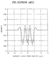
- FIG. 4 and FIG. 5 of the accompanying drawings show the results of a SOLID (Simulation of Optical Lithography In three Dimensions) simulator, wherein an exposing and developing process simulation based on a conventional photo mask as shown in FIG. 3 of the accompanying drawings is performed.
- the simulation is performed using a deep ultraviolet (DUV) stepper at a wavelength ( ⁇ ) of 0.248 ⁇ m and a numerical aperture (NA) of 0.45.
- DUV deep ultraviolet
- FIG. 3 is a layout view showing a conventional photo mask.
- a rectangular opaque mask pattern 7 for selectively blocking light is formed on a substrate, and the area where the opaque mask pattern 7 does not block the light is an optical transmission area.
- the dimensions of the rectangular opaque mask pattern 7 are as follows.
- the width 31 and length 33 of each portion of rectangular opaque mask pattern 7 are 0.42 ⁇ m and 1.18 ⁇ m, respectively, and a spacing 32 (X-axis) and a spacing 34 (y-axis) between the opaque mask patterns are 0.28 ⁇ m and 0.22 ⁇ m, respectively.
- FIG. 4 is a plan view showing an aerial image created by the simulation when a mask pattern is transferred on a substrate using the photo mask of FIG. 3.
- contour lines around the point of a reference character 5a are much denser than in other areas. These densely formed contour lines correspond to an optical transmission area between the edges of opaque mask patterns 7 (FIG. 3). Especially, in the optical transmission area between opaque mask patterns 7, light is gathered when the mask pattern is transferred, to thereby exhibit the maximum degree of the proximity effect.
- FIG. 5 is a graph representing the simulated light intensity along line a-a' of FIG. 4.
- the light intensity along line a-a' is not uniform, and is high at the portions indicated by reference numeral 5 (corresponding to reference numeral 5a of FIG. 4) by a proximity effect.
- EP-A-0,529,338 and EP-A-0,551,621 each disclose a photo mask which includes a phase shifting mask for shifting the phase of transmitted light.
- a photo mask for transferring a mask pattern onto a semiconductor wafer comprising:
- the optical transmittance control film is preferably formed of a material selected from the group consisting of spin-on-glass (SOG), photoresist (PR), silicon oxide (SiO 2 ), aluminum (Al), silicon nitride (Si 3 N 4 ), a polysilicon, titanium (Ti), titanium nitride (TiN), chromium (Cr) and tungsten (W).
- SOG spin-on-glass
- PR photoresist
- SiO 2 silicon oxide
- Al aluminum
- Si 3 N 4 silicon nitride
- a polysilicon titanium (Ti), titanium nitride (TiN), chromium (Cr) and tungsten (W).
- a proximity effect is suppressed by forming an optical transmittance control film pattern in an intersection area of the transmission area and in areas adjacent thereto, the shape of a mask pattern is exactly transferred onto a substrate, to thereby increase capacitor area.
- SOLID Simulation of Optical Lithography In three Dimensions
- the simulation is performed using a deep ultraviolet (DUV) stepper at a wavelength ( ⁇ ) of 0.248 ⁇ m and a numerical aperture (NA) of 0.45.
- DUV deep ultraviolet
- NA numerical aperture
- an optical transmission rate of optical transmittance control film is controlled as 50%.
- FIG. 6 is a layout view of a photo mask according to a first embodiment of the present invention.
- a rectangular opaque mask pattern 11 for defining an optical transmission area is formed periodically on a mask substrate (not shown).
- an optical transmittance control film pattern 10 is formed in an intersection area of the optical transmission area between the opaque mask pattern 11 and in the areas adjacent thereto.
- the optical transmittance control film pattern 10 is formed in an area defined by edges of the opaque mask pattern 11.
- the optical transmittance control film pattern 10 is formed in a parallel direction (Y-axis) with respect to the longer side of the rectangular opaque mask pattern.
- the optical transmittance control film pattern 10 maintains a uniform light intensity, thereby suppressing a proximity effect.
- the size, shape and layout of the optical transmittance control film pattern 10 can be variably controlled.
- the width and length of the optical transmittance control film pattern 10 are 0.28 ⁇ m and 0.66 ⁇ m, respectively.
- the width and length of the opaque mask pattern 11 are 0.42 ⁇ m and 1.18 ⁇ m, respectively.
- the spacings between the opaque mask patterns 11 are 0.28 ⁇ m (X-axis) and 0.22 ⁇ m (y-axis), respectively.
- FIG. 7 is a plan view showing an aerial image created by a simulation, when a mask pattern is transferred onto a substrate using the photo mask shown in FIG. 6.
- the contour lines around a reference character 13a are less dense than those in FIG. 4. Areas in which the contour lines are not densely formed correspond to an optical transmission area between opaque mask patterns 11 shown in FIG. 6. Especially, in an optical transmission area between the opaque mask patterns 11 of FIG. 6, light is not gathered when a mask pattern is transferred, thereby suppressing a proximity effect.
- FIG. 8 is a graph representing the light intensity along line b-b' of FIG. 7.
- the light intensity along line b-b' is uniform since a light intensity (reference numeral 13) is very low as compared with reference numeral 5 of FIG. 5.
- the proximity effect is suppressed when a photoresist pattern is formed using a photo mask according to the present invention.
- FIG. 9 is a layout view of a photo mask according to the second embodiment of the present invention.
- a rectangular opaque mask pattern 15 for defining an optical transmission area is formed periodically on a mask substrate (not shown). Also, an optical transmittance control film pattern 14 is formed in an intersection area of the optical transmission area between the opaque mask patterns 15. In more detail, the optical transmittance control film pattern 15 is formed in an area defined by edges of the opaque mask pattern 14. Especially, when a mask pattern is transferred onto a substrate, the optical transmittance control film pattern 15 maintains a uniform light intensity, thereby suppressing a proximity effect. Also, the optical transmittance control film pattern 14 can be formed in a part of the intersection area of the optical transmission area between the opaque mask patterns 15. At this time, the proximity effect can be suppressed by controlling the transmission rate of the optical transmittance control film pattern 14.
- the width and length of the optical transmittance control film pattern 14 are 0.28 ⁇ m and 0.22 ⁇ m, respectively.
- the dimensions (width and length) of the opaque mask pattern 15 and the length between the opaque mask pattern 15 are the same as those of the first embodiment.
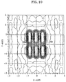
- FIG. 10 is a plan view showing an aerial image created by a simulation, when a mask pattern is transferred onto a substrate using the photo mask shown in FIG. 9.
- the contour lines around a reference character 16a are less dense than those formed in FIG. 4. Those areas where the contour lines are not densely formed correspond to an optical transmission area between an opaque mask patterns 15 as shown in FIG. 9. Especially, in an optical transmission area between the opaque mask patterns 15, light is not gathered when a mask pattern is transferred, thereby suppressing a proximity effect.
- FIG. 11 is a graph representing the light intensity along line c-c' of FIG. 10.
- the light intensity along line c-c' of FIG. 10 is relatively uniform since the light intensity at reference numeral 16 is much lower than that at reference numeral 5 of FIG. 5.
- a proximity effect is suppressed when a photoresist pattern is formed using a photo mask according to the present invention.
- FIG. 12 is a layout view of a photo mask according to the third embodiment of the present invention.
- a rectangular opaque mask pattern 20 for defining an optical transmission area is formed periodically on a mask substrate (not shown). Also, a first and second optical transmittance control film pattern 17 and 18 are formed in an intersection area of the optical transmission area between the opaque mask pattern 20 and in the areas adjacent thereto.
- the first optical transmittance control film pattern 17 is formed parallel to the longer side of the rectangular opaque mask pattern 20
- the second optical transmittance control film pattern 18 is formed perpendicular to the longer side of the rectangular opaque mask pattern 20.
- the first and second optical transmittance control film patterns 17 and 18 maintain a uniform light intensity, thereby suppressing a proximity effect.
- the width and length of the first optical transmittance control film pattern 17 are 0.28 ⁇ m and 0.42 ⁇ m, respectively, and the width and length of the second optical transmittance control film pattern 18 are 0.48 ⁇ m and 0.22 ⁇ m, respectively.
- the dimensions (width and length) of the opaque mask pattern 20 and the length between the opaque mask patterns 20 are the same as those of the first embodiment.
- FIG. 13 is a plan view showing an aerial image created by a simulation, when a mask pattern is transferred onto a substrate using the photo mask shown in FIG. 12.
- contour lines around a reference character 19a are less dense than those formed in FIG. 4. Areas where the contour lines are not densely formed correspond to an optical transmission area between an opaque mask patterns 20 as shown in FIG. 12. Especially, in an optical transmission area between an opaque mask patterns 20, light is not gathered when a mask pattern is transferred, thereby suppressing a proximity effect.
- FIG. 14 is a graph representing the light intensity along line d-d' of FIG. 13.
- the light intensity along line d-d' of FIG. 13 is very uniform since the light intensity at reference numeral 19 is much lower than that at reference numeral 5 of FIG. 5.
- the proximity effect is suppressed when a photoresist pattern is formed using a photo mask according to the present invention.
- FIG. 15A to FIG. 15D are sectional views illustrating a method for manufacturing a photo mask according to the first embodiment of the present invention.
- FIG. 15A shows a step of forming an opaque mask pattern 101 on a transparent substrate 100.
- an opaque material layer is formed on a substrate 100, a light-blocking material is used as the opaque material layer.
- a chromium layer is used as the opaque material layer.
- a photoresist layer (not shown) is formed on the opaque material layer and patterned to form a photoresist pattern (not shown) by exposing using an electron beam and developing process. Then, the opaque material is etched to form an opaque mask pattern 101 using the photoresist pattern as an etching mask. Thereafter, the photoresist pattern is removed.
- FIG. 15B shows a step of forming an optical transmittance control film 102 over the entire surface of the substrate 101.
- an optical transmittance control film 102 is formed on an opaque mask pattern 101 and a substrate 100.
- the optical transmittance control film 102 is formed of spin-on-glass (SOG), photoresist (PR), silicon oxide (SiO 2 ), aluminum (Al), silicon nitride (Si 3 N 4 ), a polysilicon, titanium (Ti), titanium nitride (TiN), chromium (Cr) or tungsten (W).
- FIG. 15C shows a step of forming a photoresist pattern (103a, 103b) for patterning the optical transmittance control film 102.
- a photoresist layer is formed on the optical transmittance control film 102 and patterned to form a photoresist pattern (103a, 103b) by exposing using an electron beam and developing process.
- the photoresist pattern (103a, 103b) is formed between the individual portions of the opaque mask pattern 101.
- FIG. 15D shows a step of forming a transmittance control film pattern (102a, 102b) between the opaque mask patterns 101.
- the transmittance control film 102 is etched to form a transmittance control film pattern (102a, 102b) using the photoresist pattern (103a, 103b) as an etching mask. Thereafter, the photoresist pattern is removed and a manufacturing process of a photo mask according to the present invention is completed.
- FIG. 16A to FIG. 16D are sectional views illustrating a method for manufacturing a photo mask according to the second embodiment of the present invention
- FIG. 16A shows a step of forming an opaque mask pattern 101 and etch stopping film 104 on a transparent substrate 100.
- an etch stopping film is formed on an opaque mask pattern 101 and a substrate 100, the etching stopping film is used as an etch stop when etching an optical transmittance control film by subsequent process.
- the etch stopping film 104 is spin-on-glass, silicon oxide or silicon nitride when the optical transmittance control film is a metal, e.g., aluminum or chromium.
- the formation of an opaque mask pattern 101 is the same as that of the first embodiment.
- FIG. 16B is a step of forming an optical transmittance control film 105 on the etch stopping film 104.
- an optical transmittance control film 105 is formed on the etch stopping film 104.
- the optical transmittance control film 105 is formed of spin-on-glass (SOG), photoresist (PR), silicon oxide (SiO 2 ), aluminum (Al), silicon nitride (Si 3 N 4 ), a polysilicon, titanium (Ti), titanium nitride (TiN), chromium (Cr) or tungsten (W).
- FIG. 16C shows a step of forming a photoresist pattern (106a, 106b) for patterning the optical transmittance control film 105 104.
- a photoresist layer is formed on the optical transmittance control film 105 and patterned the photoresist layer to form a photoresist pattern (106a, 106b) by exposing using an electron beam and developing process.
- the photoresist pattern (106a, 106b) is only formed between the opaque mask pattern 101.
- FIG. 16D shows a step of forming a transmittance control film pattern (105a, 105b) between the opaque mask pattern 101.
- the transmittance control film 105 is etched to form a transmittance control film pattern (105a, 105b) using the photoresist pattern (106a, 106b) as an etching mask. Thereafter, the photoresist pattern is removed and the manufacturing process of a photo mask according to the present invention is completed.
- FIG. 17A to FIG. 17D are sectional views illustrating a method for manufacturing a photo mask according to the third embodiment of the present invention.
- FIG. 17A shows a step of forming an photoresist layer 107 on an opaque mask pattern 101 and transparent substrate 100.
- an photoresist layer is formed on an opaque mask pattern 101 and a substrate 100.
- the formation of an opaque mask pattern 101 is the same as those of the first and second embodiments.
- FIG. 17B shows a step of forming a photoresist pattern (107a, 107b, 107c).
- a photoresist layer is patterned to form a photoresist pattern (107a, 107b, 107c) by exposing using an electron beam and developing process.
- the photoresist pattern (106a, 106b) is only formed on the opaque mask pattern 101.
- FIG. 17C shows a step of forming an optical transmittance control film 108 over the resultant material.
- an optical transmittance control film 108 is formed over the entire surface of the resultant material.
- the material used as the optical transmittance control film 108 is the same as those of the first and second embodiments.
- FIG. 17D shows a step of forming a transmittance control film pattern (108a, 108b) between the opaque mask pattern 101.
- the transmittance control film 108 is etched to form a transmittance control film pattern (108a, 108b) using a lift-off process. If so, the manufacturing process of a photo mask according to the present invention is completed.
- a proximity effect is suppressed by forming an optical transmittance control film pattern in an intersection area of the transmission area between the opaque mask pattern and in the areas adjacent thereto, the shape of a mask pattern is exactly transferred onto a substrate, thereby increasing a capacitor area and reliability of a semiconductor device.
Landscapes
- Physics & Mathematics (AREA)
- General Physics & Mathematics (AREA)
- Health & Medical Sciences (AREA)
- Toxicology (AREA)
- Preparing Plates And Mask In Photomechanical Process (AREA)
- Exposure And Positioning Against Photoresist Photosensitive Materials (AREA)
- Photosensitive Polymer And Photoresist Processing (AREA)
- Exposure Of Semiconductors, Excluding Electron Or Ion Beam Exposure (AREA)
Claims (5)
- Photomaske zur Übertragung eines Maskenmusters auf einen Halbleiterwafer, mit:dadurch gekennzeichnet, daß die Photomaske ferner ein optisches Durchlässigkeitssteuerungsfilmmuster (10; 14; 17, 18) aufweist, das innerhalb des optischen Transmissionsbereiches einen Nahwirkungseffekt unterdrückt, wobei das opake Maskenmuster (11; 15; 20) ein zweidimensionales Feld von Maskenteilen bildet, die gleich große rechtwinklige Formen haben, die derart mit regelmäßigen Abständen zueinander angeordnet sind, daß horizontal benachbarte Maskenteile durch säulenförmige optischen Transmissionsbereiche und vertikal benachbarte Maskenteile durch reihenweise angeordnete optische Transmissionsbereiche getrennt sind, und wobei das optische Durchlässigkeitssteuerungsfilmmuster an den Teilen des optischen Transmissionsbereiches gebildet ist, an denen die säulenförmigen optischen Transmissionsbereiche die reihenweise angeordneten Transmissionsbereiche kreuzen.einem transparenten Substrat (100); und,einem opaken Maskenmuster (11; 15; 20), das auf dem Substrat gebildet ist, wobei das opake Masken. muster einen optischen Transmissionsbereich zwischen Kanten von Teilen des opaken Maskenmusters definiert, die selektiv Licht blockieren,
- Photomaske nach Anspruch 1, bei der das optische Durchlässigkeitssteuerungsfilmmuster (10; 14; 17, 18) aus einem Material gebildet ist, das aus der Gruppe ausgewählt ist, die aus aufgeschleudertem Glas (spin-on-glas, SOG), Photoresist (PR), Siliciumoxid (SiO2), Aluminium (Al), Siliciumnitrid (Si3N4), Polysilicium, Titan (Ti), Titannitrid (TiN), Chrom (Cr) und Wolfram (W) besteht.
- Photomaske nach Anspruch 1 oder 2, bei der das optische Durchlässigkeitssteuerungsfilmmuster (10; 14; 17, 18) jeweilige optische Transmissionsbereiche des Substrates überdeckt.
- Photomaske nach Anspruch 3, bei der sich das optische Durchlässigkeitssteuerungsfilmmuster (10) in die säulenförmigen optischen Transmissionsbereiche zwischen den horizontal benachbarten Maskenteilen erstreckt.
- Photomaske nach Anspruch 4, bei der sich das optische Durchlässigkeitssteuerungsfilmmuster (18) in die reihenweise angeordneten optischen Transmissionsbereiche zwischen den vertikal benachbarten Maskenteilen erstreckt.
Applications Claiming Priority (2)
| Application Number | Priority Date | Filing Date | Title |
|---|---|---|---|
| KR1019940002310A KR0138297B1 (ko) | 1994-02-07 | 1994-02-07 | 포토 마스크 및 그 제조 방법 |
| KR9402310 | 1994-02-07 |
Publications (2)
| Publication Number | Publication Date |
|---|---|
| EP0666503A1 EP0666503A1 (de) | 1995-08-09 |
| EP0666503B1 true EP0666503B1 (de) | 2000-08-16 |
Family
ID=19376972
Family Applications (1)
| Application Number | Title | Priority Date | Filing Date |
|---|---|---|---|
| EP95300104A Expired - Lifetime EP0666503B1 (de) | 1994-02-07 | 1995-01-09 | Photomaske |
Country Status (6)
| Country | Link |
|---|---|
| US (1) | US5725973A (de) |
| EP (1) | EP0666503B1 (de) |
| JP (1) | JPH07219207A (de) |
| KR (1) | KR0138297B1 (de) |
| CN (1) | CN1088525C (de) |
| DE (1) | DE69518345T2 (de) |
Cited By (1)
| Publication number | Priority date | Publication date | Assignee | Title |
|---|---|---|---|---|
| DE10126130A1 (de) * | 2001-05-29 | 2002-12-12 | Infineon Technologies Ag | Verfahren zur Herstellung von Kontaktlöchern |
Families Citing this family (43)
| Publication number | Priority date | Publication date | Assignee | Title |
|---|---|---|---|---|
| JPH08297692A (ja) * | 1994-09-16 | 1996-11-12 | Mitsubishi Electric Corp | 光近接補正装置及び方法並びにパタン形成方法 |
| KR0161437B1 (ko) * | 1995-09-19 | 1999-02-01 | 김광호 | 반도체장치의 미세패턴 형성방법 |
| JP3431387B2 (ja) * | 1996-03-14 | 2003-07-28 | 株式会社東芝 | 露光強度分布表示方法とマスクパターン編集装置 |
| US6120942A (en) | 1997-02-18 | 2000-09-19 | Micron Technology, Inc. | Method for making a photomask with multiple absorption levels |
| US6078738A (en) * | 1997-05-08 | 2000-06-20 | Lsi Logic Corporation | Comparing aerial image to SEM of photoresist or substrate pattern for masking process characterization |
| KR100298192B1 (ko) * | 1997-12-27 | 2002-01-17 | 박종섭 | 포토바이어스개선을위한포토마스크 |
| KR100283408B1 (ko) * | 1998-01-21 | 2001-04-02 | 김영환 | 반도체용마스크 |
| KR100303799B1 (ko) * | 1998-03-19 | 2001-11-30 | 황인길 | 반도체소자용마스크패턴 |
| JP3367460B2 (ja) * | 1999-04-09 | 2003-01-14 | 日本電気株式会社 | 半導体装置の製造方法およびこれに用いるフォトマスク |
| TW497165B (en) * | 1999-06-30 | 2002-08-01 | Hitachi Ltd | Method for manufacturing semiconductor integrated circuit device, optical mask used therefor, method for manufacturing the same, and mask blanks used therefor |
| US6258490B1 (en) | 1999-07-09 | 2001-07-10 | International Business Machines Corporation | Transmission control mask utilized to reduce foreshortening effects |
| US6844118B2 (en) | 1999-08-19 | 2005-01-18 | Micron Technology, Inc. | Method and layout for high density reticle |
| US6465138B1 (en) * | 1999-08-19 | 2002-10-15 | William Stanton | Method for designing and making photolithographic reticle, reticle, and photolithographic process |
| US6682861B2 (en) | 1999-09-30 | 2004-01-27 | Photronics, Inc. | Disposable hard mask for phase shift photomask plasma etching |
| US6472107B1 (en) | 1999-09-30 | 2002-10-29 | Photronics, Inc. | Disposable hard mask for photomask plasma etching |
| US6569574B2 (en) | 1999-10-18 | 2003-05-27 | Micron Technology, Inc. | Methods of patterning radiation, methods of forming radiation-patterning tools, and radiation-patterning tools |
| US6294295B1 (en) | 2000-03-06 | 2001-09-25 | Taiwan Semiconductor Manufacturing Company | Variable transmittance phase shifter to compensate for side lobe problem on rim type attenuating phase shifting masks |
| US6465139B1 (en) * | 2000-06-05 | 2002-10-15 | Taiwan Semiconductor Manufacturing Company, Ltd. | Mask pattern for defining a floating gate region |
| JP2002341513A (ja) * | 2001-05-15 | 2002-11-27 | Oki Electric Ind Co Ltd | 露光用マスク及びそれを用いた半導体装置の製造方法 |
| KR100438433B1 (ko) * | 2001-06-26 | 2004-07-03 | 삼성전자주식회사 | 피디에이 겸용 디지털 카메라 통신 휴대 장치 |
| US6835504B2 (en) * | 2002-05-13 | 2004-12-28 | Macronix International Co., Ltd. | Photomask with illumination control over patterns having varying structural densities |
| JP4361248B2 (ja) * | 2002-07-31 | 2009-11-11 | 富士通マイクロエレクトロニクス株式会社 | フォトマスク、そのパターン欠陥検出方法及びそれを用いたパターン形成方法 |
| US6887629B2 (en) * | 2002-08-21 | 2005-05-03 | Micron Technology, Inc. | Radiation-patterning tool |
| US7049034B2 (en) * | 2003-09-09 | 2006-05-23 | Photronics, Inc. | Photomask having an internal substantially transparent etch stop layer |
| US7141338B2 (en) * | 2002-11-12 | 2006-11-28 | Infineon Technologies Ag | Sub-resolution sized assist features |
| US6933084B2 (en) * | 2003-03-18 | 2005-08-23 | Photronics, Inc. | Alternating aperture phase shift photomask having light absorption layer |
| US7074525B2 (en) * | 2003-04-29 | 2006-07-11 | Infineon Technologies Ag | Critical dimension control of printed features using non-printing fill patterns |
| US7118833B2 (en) * | 2003-09-26 | 2006-10-10 | Flipchip International, Llc | Forming partial-depth features in polymer film |
| KR20050033473A (ko) * | 2003-10-06 | 2005-04-12 | 마츠시타 덴끼 산교 가부시키가이샤 | 포토마스크 및 패턴형성방법 |
| US7560197B2 (en) * | 2004-02-23 | 2009-07-14 | Kabushiki Kaisha Toshiba | Mask pattern data producing method, patterning method, reticle correcting method, reticle manufacturing method, and semiconductor apparatus manufacturing method |
| US20060051681A1 (en) * | 2004-09-08 | 2006-03-09 | Phototronics, Inc. 15 Secor Road P.O. Box 5226 Brookfield, Conecticut | Method of repairing a photomask having an internal etch stop layer |
| US20060157898A1 (en) * | 2005-01-18 | 2006-07-20 | International Business Machines Corporation | Imprint reference template for multilayer or multipattern registration and method therefor |
| EP1992988A4 (de) * | 2006-03-09 | 2011-12-28 | Panasonic Corp | Photomaske, verfahren zur herstellung einer solchen photomaske und musterbildungsverfahren mit einer solchen photomaske |
| KR100746625B1 (ko) * | 2006-06-29 | 2007-08-08 | 주식회사 하이닉스반도체 | 높은 빔 컨트라스트를 나타내는 포토마스크 및 그제조방법과, 이를 이용한 노광방법 |
| CN101446758B (zh) * | 2007-11-28 | 2011-05-11 | 中国科学院微电子研究所 | 改善微机械非制冷红外成像芯片中反光板平整度的方法 |
| KR100976791B1 (ko) * | 2007-12-17 | 2010-08-19 | 주식회사 동부하이텍 | 이미지 센서 및 그 제조 방법 |
| US7939225B2 (en) * | 2008-01-09 | 2011-05-10 | Macronix International Co., Ltd. | Mask for controlling line end shortening and corner rounding arising from proximity effects |
| CN103616804B (zh) * | 2013-12-05 | 2015-09-02 | 中山新诺科技有限公司 | 一种拼贴法制备单片集成电容触摸屏的动态掩膜板系统 |
| CN103631095B (zh) * | 2013-12-05 | 2015-11-25 | 中山新诺科技有限公司 | 一种拼贴法制备单片集成电容触摸屏的动态电子掩膜板系统 |
| CN104752169B (zh) * | 2013-12-30 | 2018-12-21 | 中芯国际集成电路制造(上海)有限公司 | 掩膜图形的形成方法 |
| TWI604267B (zh) * | 2014-12-17 | 2017-11-01 | Hoya股份有限公司 | 光罩之製造方法及顯示裝置之製造方法 |
| CN109143774A (zh) * | 2018-07-18 | 2019-01-04 | 深圳市华星光电半导体显示技术有限公司 | 掩膜板及金属线的制作方法 |
| CN114815520B (zh) * | 2022-04-27 | 2024-12-17 | 上海华力集成电路制造有限公司 | 一种用于opc模型验证的参数自动寻优方法及系统 |
Family Cites Families (4)
| Publication number | Priority date | Publication date | Assignee | Title |
|---|---|---|---|---|
| US4902899A (en) * | 1987-06-01 | 1990-02-20 | International Business Machines Corporation | Lithographic process having improved image quality |
| US5208124A (en) * | 1991-03-19 | 1993-05-04 | Hewlett-Packard Company | Method of making a mask for proximity effect correction in projection lithography |
| JPH0534897A (ja) * | 1991-07-30 | 1993-02-12 | Fujitsu Ltd | 光学マスク及びその製造方法 |
| US5382483A (en) * | 1992-01-13 | 1995-01-17 | International Business Machines Corporation | Self-aligned phase-shifting mask |
-
1994
- 1994-02-07 KR KR1019940002310A patent/KR0138297B1/ko not_active Expired - Fee Related
-
1995
- 1995-01-09 EP EP95300104A patent/EP0666503B1/de not_active Expired - Lifetime
- 1995-01-09 DE DE69518345T patent/DE69518345T2/de not_active Expired - Fee Related
- 1995-01-10 CN CN95101151A patent/CN1088525C/zh not_active Expired - Fee Related
- 1995-01-12 JP JP300095A patent/JPH07219207A/ja active Pending
-
1996
- 1996-04-16 US US08/632,834 patent/US5725973A/en not_active Expired - Fee Related
Cited By (1)
| Publication number | Priority date | Publication date | Assignee | Title |
|---|---|---|---|---|
| DE10126130A1 (de) * | 2001-05-29 | 2002-12-12 | Infineon Technologies Ag | Verfahren zur Herstellung von Kontaktlöchern |
Also Published As
| Publication number | Publication date |
|---|---|
| CN1121189A (zh) | 1996-04-24 |
| JPH07219207A (ja) | 1995-08-18 |
| EP0666503A1 (de) | 1995-08-09 |
| US5725973A (en) | 1998-03-10 |
| DE69518345D1 (de) | 2000-09-21 |
| CN1088525C (zh) | 2002-07-31 |
| DE69518345T2 (de) | 2001-01-25 |
| KR0138297B1 (ko) | 1998-06-01 |
| KR950025858A (ko) | 1995-09-18 |
Similar Documents
| Publication | Publication Date | Title |
|---|---|---|
| EP0666503B1 (de) | Photomaske | |
| US7494765B2 (en) | Method for patterning photoresist pillars using a photomask having a plurality of chromeless nonprinting phase shifting windows | |
| US5656400A (en) | Photomask and pattern forming method employing the same | |
| JP2593601B2 (ja) | 位相シフトマスクの作製方法 | |
| KR100299343B1 (ko) | 코너형이미지형성방법및그것에의해형성된포토마스크 | |
| EP0464492A1 (de) | Photomaske, die in der Photolithographie benutzt wird und ein Herstellungsverfahren derselben | |
| JPH04136854A (ja) | 半導体装置の製造方法 | |
| US5888678A (en) | Mask and simplified method of forming a mask integrating attenuating phase shifting mask patterns and binary mask patterns on the same mask substrate | |
| US7291425B2 (en) | Radiation patterning tools, and methods of forming radiation patterning tools | |
| US5837426A (en) | Photolithographic process for mask programming of read-only memory devices | |
| JP4497259B2 (ja) | フォトマスク及びこれを用いた半導体素子の微細パターン形成方法 | |
| US6428938B1 (en) | Phase-shift mask for printing high-resolution images and a method of fabrication | |
| KR20020081345A (ko) | 반도체 소자 피처들을 제조하기 위한 무크롬 교번형 레티클 | |
| US20060204859A1 (en) | An extra dose trim mask, method of manufacture, and lithographic process using the same | |
| KR19980026623A (ko) | 위상 쉬프트 마스크 및 그 제조방법 | |
| US6800402B2 (en) | Phase-shifting mask and method of forming pattern using the same | |
| US7144690B2 (en) | Photolithographic methods of using a single reticle to form overlapping patterns | |
| KR20010002127A (ko) | 하프톤형 위상반전마스크 및 그 형성방법 | |
| US5658695A (en) | Method for fabricating phase shift mask comprising the use of a second photoshield layer as a sidewall | |
| US5712063A (en) | Phase shift mask comprising light shielding regions having a multiple box structure | |
| US20030203286A1 (en) | High-transmittance halftone phase shift mask and manufacturing method of semiconductor device | |
| KR100380982B1 (ko) | 위상반전마스크및그제조방법 | |
| JP2734396B2 (ja) | 露光マスク | |
| JP3257232B2 (ja) | 位相シフトマスク | |
| US7226707B2 (en) | Methods of printing structures |
Legal Events
| Date | Code | Title | Description |
|---|---|---|---|
| PUAI | Public reference made under article 153(3) epc to a published international application that has entered the european phase |
Free format text: ORIGINAL CODE: 0009012 |
|
| AK | Designated contracting states |
Kind code of ref document: A1 Designated state(s): DE FR GB IT NL |
|
| 17P | Request for examination filed |
Effective date: 19960123 |
|
| 17Q | First examination report despatched |
Effective date: 19970701 |
|
| RTI1 | Title (correction) |
Free format text: PHOTO MASK |
|
| GRAG | Despatch of communication of intention to grant |
Free format text: ORIGINAL CODE: EPIDOS AGRA |
|
| GRAG | Despatch of communication of intention to grant |
Free format text: ORIGINAL CODE: EPIDOS AGRA |
|
| GRAH | Despatch of communication of intention to grant a patent |
Free format text: ORIGINAL CODE: EPIDOS IGRA |
|
| GRAH | Despatch of communication of intention to grant a patent |
Free format text: ORIGINAL CODE: EPIDOS IGRA |
|
| GRAA | (expected) grant |
Free format text: ORIGINAL CODE: 0009210 |
|
| AK | Designated contracting states |
Kind code of ref document: B1 Designated state(s): DE FR GB IT NL |
|
| PG25 | Lapsed in a contracting state [announced via postgrant information from national office to epo] |
Ref country code: IT Free format text: LAPSE BECAUSE OF FAILURE TO SUBMIT A TRANSLATION OF THE DESCRIPTION OR TO PAY THE FEE WITHIN THE PRE;WARNING: LAPSES OF ITALIAN PATENTS WITH EFFECTIVE DATE BEFORE 2007 MAY HAVE OCCURRED AT ANY TIME BEFORE 2007. THE CORRECT EFFECTIVE DATE MAY BE DIFFERENT FROM THE ONE RECORDED.SCRIBED TIME-LIMIT Effective date: 20000816 Ref country code: FR Free format text: LAPSE BECAUSE OF FAILURE TO SUBMIT A TRANSLATION OF THE DESCRIPTION OR TO PAY THE FEE WITHIN THE PRESCRIBED TIME-LIMIT Effective date: 20000816 |
|
| REF | Corresponds to: |
Ref document number: 69518345 Country of ref document: DE Date of ref document: 20000921 |
|
| EN | Fr: translation not filed | ||
| PLBE | No opposition filed within time limit |
Free format text: ORIGINAL CODE: 0009261 |
|
| STAA | Information on the status of an ep patent application or granted ep patent |
Free format text: STATUS: NO OPPOSITION FILED WITHIN TIME LIMIT |
|
| 26N | No opposition filed | ||
| REG | Reference to a national code |
Ref country code: GB Ref legal event code: IF02 |
|
| PGFP | Annual fee paid to national office [announced via postgrant information from national office to epo] |
Ref country code: NL Payment date: 20090104 Year of fee payment: 15 Ref country code: DE Payment date: 20090123 Year of fee payment: 15 |
|
| PGFP | Annual fee paid to national office [announced via postgrant information from national office to epo] |
Ref country code: GB Payment date: 20090114 Year of fee payment: 15 |
|
| REG | Reference to a national code |
Ref country code: NL Ref legal event code: V1 Effective date: 20100801 |
|
| GBPC | Gb: european patent ceased through non-payment of renewal fee |
Effective date: 20100109 |
|
| PG25 | Lapsed in a contracting state [announced via postgrant information from national office to epo] |
Ref country code: NL Free format text: LAPSE BECAUSE OF NON-PAYMENT OF DUE FEES Effective date: 20100801 |
|
| PG25 | Lapsed in a contracting state [announced via postgrant information from national office to epo] |
Ref country code: DE Free format text: LAPSE BECAUSE OF NON-PAYMENT OF DUE FEES Effective date: 20100803 |
|
| PG25 | Lapsed in a contracting state [announced via postgrant information from national office to epo] |
Ref country code: GB Free format text: LAPSE BECAUSE OF NON-PAYMENT OF DUE FEES Effective date: 20100109 |