EP0666782B1 - Accumulateur a bande - Google Patents
Accumulateur a bande Download PDFInfo
- Publication number
- EP0666782B1 EP0666782B1 EP94922166A EP94922166A EP0666782B1 EP 0666782 B1 EP0666782 B1 EP 0666782B1 EP 94922166 A EP94922166 A EP 94922166A EP 94922166 A EP94922166 A EP 94922166A EP 0666782 B1 EP0666782 B1 EP 0666782B1
- Authority
- EP
- European Patent Office
- Prior art keywords
- tape
- ring
- strip
- belt
- roller
- Prior art date
- Legal status (The legal status is an assumption and is not a legal conclusion. Google has not performed a legal analysis and makes no representation as to the accuracy of the status listed.)
- Expired - Lifetime
Links
Images

Classifications
-
- B—PERFORMING OPERATIONS; TRANSPORTING
- B21—MECHANICAL METAL-WORKING WITHOUT ESSENTIALLY REMOVING MATERIAL; PUNCHING METAL
- B21C—MANUFACTURE OF METAL SHEETS, WIRE, RODS, TUBES, PROFILES OR LIKE SEMI-MANUFACTURED PRODUCTS OTHERWISE THAN BY ROLLING; AUXILIARY OPERATIONS USED IN CONNECTION WITH METAL-WORKING WITHOUT ESSENTIALLY REMOVING MATERIAL
- B21C49/00—Devices for temporarily accumulating material
-
- B—PERFORMING OPERATIONS; TRANSPORTING
- B65—CONVEYING; PACKING; STORING; HANDLING THIN OR FILAMENTARY MATERIAL
- B65H—HANDLING THIN OR FILAMENTARY MATERIAL, e.g. SHEETS, WEBS, CABLES
- B65H20/00—Advancing webs
- B65H20/30—Arrangements for accumulating surplus web
-
- B—PERFORMING OPERATIONS; TRANSPORTING
- B65—CONVEYING; PACKING; STORING; HANDLING THIN OR FILAMENTARY MATERIAL
- B65H—HANDLING THIN OR FILAMENTARY MATERIAL, e.g. SHEETS, WEBS, CABLES
- B65H2408/00—Specific machines
- B65H2408/20—Specific machines for handling web(s)
- B65H2408/21—Accumulators
- B65H2408/211—Coil type accumulator
Definitions
- the invention relates to a tape storage device, consisting of an outer ring of drivable support rollers arranged radially with respect to the vertical ring axis for the upright inclusion of an outer tape roll with a tape feed from the outside, from a concentric inner ring of freely rotatable, radial support rollers for one with the outer tape roll by a deflection loop connected inner tape reel and from a roll core for the inner tape reel forming roller cage, from the axially parallel rollers one of which leads the tape as a discharge roller to an inclined take-off roller within the roller cage.
- the metal band entering the band store is wound from the outside onto an outer band wrap which rests on its edge on an annular rotary table or on an outer ring of drivable, preferably conical, idler rollers. Since this outer tape roll does not require a roll cage as the winding core, the inner diameter of the outer tape roll is only determined by the ratio of the tape feed speed to the number of revolutions of the table.
- the tape runs over a deflection loop to an inner tape roll, which is received by an inner ring provided within the annular turntable of freely rotatable supporting rollers and is supported on a winding core from a roller basket, which encloses an inclined take-off roller, via which Tape is pulled from the inside of the inner tape reel in the opposite direction to the direction of rotation of the incoming tape by a basket roller serving as a reel roll from the tape store.
- the tape is wound up with the same number of turns on the two tape coils during storage due to the deflection loop rotating at a speed corresponding to half the difference between the tape entry and the tape exit speed.
- the size of the deflection loop depends on the strip thickness and, in particular in the case of thicker strips, requires comparatively large bending radii, which requires correspondingly large outside diameters for the rotary table.
- the compressive forces exerted on the belt in the region of the deflection loop on the side of the outer belt winding can cause the belt to buckle.
- the position of the outer tape roll on the turntable is not stable due to various influences.
- the invention is therefore based on the object to improve a tape store of the type described with simple constructive means that it is suitable for thin as well as for thick sheet metal strips that its outer diameter can be chosen to be comparatively small regardless of the respective strip thickness and that there is a stable position for the outer tape winding.
- the invention solves this problem in that, in a tape storage device of the type mentioned, between the outer and the inner ring of the idler rollers for the deflection loop around the ring axis with a revolution speed corresponding to half the difference between the tape feed and the tape run speed of the memory Drivable deflection roller is provided and that the outer ring of the idler rollers has a ring of inclined rollers on the inside, which rise radially inwards and / or incline with respect to a radial orientation with respect to the ring axis in the opposite direction to the direction of rotation of the outer tape roll.
- the bending radius for the deflection loop of the tape is determined by the radius of the deflection roller and not by that of the tape thickness and the belt material dependent, free bending behavior of the belt, so that when the deflection roller is designed for the smallest permissible bending radius of the belt, which requires the largest bending radius from the belts suitable for the storage device, all the belts form the same deflection loops and the outer diameter of the belt storage device also for thick bands can be kept comparatively small.
- the tensile forces exerted on the belt in the area of the deflection loop by the deflection roller not only ensure that the belt is attached to the sheathing of the deflection roller, but also enable thin strips to be stored, because it is no longer possible to buckle due to pressure forces otherwise occurring in the deflection area.
- the outer tape reel In order to be able to take full advantage of a deflecting roller rotating between the two tape reels for the tape deflection, it must be ensured that the outer tape reel is in a stable position, which is not supported by a roller cage or the like.
- the ring of inclined rollers is provided, which, due to their inclined position, urge the inner turns of the outer tape roll reaching their area radially outward, so that a stable state of equilibrium results.
- the inclined rollers can be inclined both about an axis running in the circumferential direction of the tape roll and about a vertical axis.
- the position of the inner windings of the outer tape reel can be determined, so that constant working conditions exist for the loop-forming deflection roller between the two tape reels.
- the inclined rollers can be provided with a thrust collar in the area of their inner end, which results in a guide for the inner winding of the tape winding without hindering the unwinding of the innermost tape winding.
- the support rollers of the outer ring can be arranged sloping inwards, which also supports the stabilization of the position of the outer tape roll.
- the control of the drive for the deflection roller between the two tape reels must be controlled as a function of the tape feed and tape speed of the tape storage.
- the speed control of the drive for the deflection roller can control the torque as a function of the thickness and the width of the tape to be stored. This allows an advantageous adaptation to the tape to be stored with regard to the deflection conditions in the region of the deflection loop between the two tape reels.
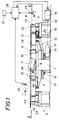
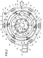
- the tape storage device essentially consists of a frame 2 which surrounds a table 1 in an annular manner and which carries an outer rim of driven support rollers 3 which are aligned radially with respect to the rim axis for the upright reception of an outer tape roll 4a.
- the table 1 has a concentric inner ring of likewise radially oriented support rollers 5, which are freely rotatable and extend radially outward from a roller cage 6, as can be seen in particular from FIG. 2.
- an inclined take-off roller 7 is provided, to which the belt 8 is fed from a discharge roller 9, which forms one of the rollers 10 of the roller cage 6.
- a deflection roller 11 is provided, which is freely rotatably mounted on an arm 12 of a rotating ring 13 and can be rotated around the table 1 with this rotating ring 13.
- the turntable 13 which is rotatably mounted on the table 1 is provided with a toothed ring 14 which meshes with a pinion 15.
- a motor 18 connected via a propeller shaft 16 to a gear 17 is provided, so that with the aid of the deflection roller 11 between the outer tape roll 4a and an inner tape roll 4b, which is wound onto the roller cage 6 and edgewise on the Supports support rollers 5 of the inner ring, a deflection loop 19 can be pulled, to the A support roller 20 is supported on the arm 12 for the deflection roller 11.
- the band 8 which runs into the band storage device via a band inlet 21 formed from a pair of rollers, reaches the support rollers 3 of the outer ring, which according to FIG. 1 are driven by a motor 22 with the interposition of a corresponding gear 23 via articulated shafts 24 and angular drives 25.
- the belt conveyance via the driven idler rollers 3 of the outer ring causes the band entering the band storage device to be wound into a band wrap 4a on the idler rollers 3.
- a ring of oblique rollers 26 is assigned to the outside of the idler rollers 3 on the inside, which according to the exemplary embodiment on the one hand rise towards the ring axis (FIG.
- the tape From the innermost turn of the outer tape roll 4a, the tape merges in a deflection loop 19 into the inner tape roll 4b, which is wound onto the roller cage 6 from the outside, the tape 8 moving inward from the innermost turn via the discharge roller 9 to the inclined take-off roller 7 from which it runs out of the tape storage.
- the deflection roller 11 rotates at half the tape feed speed, which Tape with the same number of turns is wound on the inner and outer tapes 4b and 4a.
- the deflection roller 11 moves in the opposite direction to the winding direction at half the tape running speed, and the tape turns are removed evenly from both the outer and the inner tape roll.
- a control device 28 is provided, which is connected on the one hand to a speed sensor 29 for the tape 8 entering the tape store and on the other hand to a speed transmitter 30 for the tape leaving the tape store, as is indicated in the block diagram in FIG. 1.
- the motor 18 is controlled for the deflection roller 11, by means of which the deflection loop 19 is advantageously formed, largely independently of the sizes and properties of the belt used in each case.
- the torque of the motor can also be regulated via the control device 28.
- the strip thickness is input via an input 31 into the control device 28, which, based on a predetermined dependency between the strip thickness and the required torque, presents a setpoint torque which is compared with the actual torque detected via a torque sensor 32, so that a corresponding difference between the setpoint and actual value Adjustment can take place.
- additional influencing variables such as the width of the strip to be stored or material properties, for controlling the torque of the motor 18 and thus the effective tensile stresses in the region of the deflection loop 19 can be taken into account.
- an outer roller basket 33 is provided, the basket rollers of which are designated by 34.
- This roller cage 33 is, however, not absolutely necessary for the actual tape storage in two opposite tape coils 4a and 4b connected by a deflection loop 19, as are the support rollers 35 and 36 for the tape in the area between the discharge roller 9 and the take-off roller 7, and for that leaking belt after the take-off roll can possibly be omitted.
Landscapes
- Engineering & Computer Science (AREA)
- Mechanical Engineering (AREA)
- Winding, Rewinding, Material Storage Devices (AREA)
- Winding Of Webs (AREA)
- Advancing Webs (AREA)
- Controlling Rewinding, Feeding, Winding, Or Abnormalities Of Webs (AREA)
- Storage Of Web-Like Or Filamentary Materials (AREA)
Abstract
Claims (4)
- Accumulateur à bande, constitué d'une couronne extérieure formée de rouleaux-support (3) susceptibles d'être entraînés, disposés radialement par rapport à l'axe vertical de la couronne, en vue de supporter sur champ, verticalement, un enroulement de bande (4a) extérieur avec une amenée de bande (21) venant de l'extérieur, d'une couronne intérieure, concentrique, formée de rouleaux-support (5) radiaux, montés de façon à pouvoir tourner librement et destinés à un enroulement de bande intérieure (4b) relié à l'enroulement de bande extérieure (4a) par une boucle de déviation (19), et d'une corbeille à rouleaux (6), constituant un noyau d'enroulement pour l'enroulement de bande intérieure (4b), corbeille à rouleaux des rouleaux (10) à axes parallèles desquels l'un d'entre eux guide la bande (8), à titre de rouleau d'évacuation (9), vers un rouleau d'extraction (7) placé obliquement à l'intérieur de la corbeille à rouleaux (6), caractérisé en ce que, entre la couronne extérieure et la couronne intérieure des rouleaux-support (3 et 5), est prévu, pour la boucle de déviation (19), un rouleau de renvoi (11) susceptible d'être entraîné, en tournant autour de l'axe de couronne, à une vitesse de rotation correspondant à la demi-différence entre la vitesse d'amenée de bande et la vitesse d'évacuation de bande de l'accumulateur, et en ce que la couronne extérieure des rouleaux-support (5) présente, intérieurement, une couronne de rouleaux obliques (26) s'étendant radialement en montant vers l'intérieur ou montant radialement vers l'intérieur, par rapport à une orientation radiale par rapport à l'axe de couronne, en étant inclinés en sens inverse, vis-à-vis de la direction périphérique de l'enroulement de bande extérieure (4a).
- Accumulateur à bande selon la revendication 1, caractérisé en ce que les rouleaux obliques (26) sont pourvus d'une collerette de franchissement (27) dans la zone de leur extrémité intérieure.
- Accumulateur à bande selon la revendication 1 ou 2, caractérisé en ce que les rouleaux-support (3) de la couronne extérieure sont disposés en allant en descendant vers l'intérieur.
- Accumulateur à bande selon l'une des revendications 1 à 3, caractérisé en ce qu'à la régulation de vitesse de l'entraînement du rouleau de renvoi (11) est susceptible d'être superposée une régulation de couple, faite en fonction de l'épaisseur et de la largeur de la bande (8) à stocker.
Applications Claiming Priority (3)
| Application Number | Priority Date | Filing Date | Title |
|---|---|---|---|
| AT0175293A AT401381B (de) | 1993-09-01 | 1993-09-01 | Bandspeicher |
| AT1752/93 | 1993-09-01 | ||
| PCT/AT1994/000113 WO1995006528A1 (fr) | 1993-09-01 | 1994-08-12 | Accumulateur a bande |
Publications (2)
| Publication Number | Publication Date |
|---|---|
| EP0666782A1 EP0666782A1 (fr) | 1995-08-16 |
| EP0666782B1 true EP0666782B1 (fr) | 1997-05-21 |
Family
ID=3520242
Family Applications (1)
| Application Number | Title | Priority Date | Filing Date |
|---|---|---|---|
| EP94922166A Expired - Lifetime EP0666782B1 (fr) | 1993-09-01 | 1994-08-12 | Accumulateur a bande |
Country Status (7)
| Country | Link |
|---|---|
| US (1) | US5575434A (fr) |
| EP (1) | EP0666782B1 (fr) |
| AT (1) | AT401381B (fr) |
| BR (1) | BR9405565A (fr) |
| CA (1) | CA2148134C (fr) |
| DE (1) | DE59402825D1 (fr) |
| WO (1) | WO1995006528A1 (fr) |
Families Citing this family (4)
| Publication number | Priority date | Publication date | Assignee | Title |
|---|---|---|---|---|
| WO1997035797A2 (fr) * | 1996-03-27 | 1997-10-02 | Oce Printing Systems Gmbh | Dispositif de stockage intermediaire pour materiau en bande |
| FR2751629A1 (fr) * | 1996-07-24 | 1998-01-30 | Protection Decoration Conditio | Accumulateur tampon pour une ligne de traitement en continu utilisant un produit en forme de ruban fourni par une bobine |
| KR100313474B1 (ko) * | 1999-04-13 | 2001-11-15 | 원웅재 | 로터리식 루퍼 |
| KR102369381B1 (ko) * | 2019-06-13 | 2022-03-02 | 주식회사 디엠씨 | 버티컬 스트립 어큐물레이터 |
Family Cites Families (12)
| Publication number | Priority date | Publication date | Assignee | Title |
|---|---|---|---|---|
| US3341139A (en) * | 1966-03-03 | 1967-09-12 | Armco Steel Corp | Apparatus and method for accumulating metallic strip and the like |
| US3782662A (en) * | 1971-02-24 | 1974-01-01 | Armco Steel Corp | Simplified strip accumulation |
| BE792974A (fr) * | 1971-12-21 | 1973-04-16 | Tube Prod Ltd | Accumulateur pour bande |
| JPS5220184B2 (fr) * | 1973-12-26 | 1977-06-01 | ||
| AT333691B (de) * | 1974-02-22 | 1976-12-10 | Ap Planungsgesellschaft M B H | Spiralbandspeicher |
| JPS5717326A (en) * | 1980-07-05 | 1982-01-29 | Nippon Steel Corp | Strip storing equipment |
| AT371743B (de) * | 1981-09-30 | 1983-07-25 | Voest Alpine Ag | Bandspeicher, insbesondere fuer blechbaender |
| US4473193A (en) * | 1983-01-13 | 1984-09-25 | Guild International Inc. | Helical feed-in mechanism for strip accumulator |
| JPS59203045A (ja) * | 1983-05-02 | 1984-11-17 | Hitachi Ltd | 帯状物のル−ピング装置 |
| DE3321786C2 (de) * | 1983-06-16 | 1987-03-19 | Dr. Weusthoff GmbH, 4000 Düsseldorf | Bandspeichermaschine |
| JPS6289527A (ja) * | 1985-10-15 | 1987-04-24 | Mitsubishi Heavy Ind Ltd | 帯板貯蔵装置 |
| SU1340855A1 (ru) * | 1986-03-03 | 1987-09-30 | Старо-Краматорский машиностроительный завод им.Орджоникидзе | Накопитель спирального типа дл прокатываемой полосы |
-
1993
- 1993-09-01 AT AT0175293A patent/AT401381B/de not_active IP Right Cessation
-
1994
- 1994-08-12 BR BR9405565-3A patent/BR9405565A/pt not_active Application Discontinuation
- 1994-08-12 DE DE59402825T patent/DE59402825D1/de not_active Expired - Fee Related
- 1994-08-12 CA CA002148134A patent/CA2148134C/fr not_active Expired - Fee Related
- 1994-08-12 WO PCT/AT1994/000113 patent/WO1995006528A1/fr not_active Ceased
- 1994-08-12 EP EP94922166A patent/EP0666782B1/fr not_active Expired - Lifetime
- 1994-08-12 US US08/433,419 patent/US5575434A/en not_active Expired - Fee Related
Also Published As
| Publication number | Publication date |
|---|---|
| WO1995006528A1 (fr) | 1995-03-09 |
| BR9405565A (pt) | 1999-09-08 |
| AT401381B (de) | 1996-08-26 |
| DE59402825D1 (de) | 1997-06-26 |
| EP0666782A1 (fr) | 1995-08-16 |
| US5575434A (en) | 1996-11-19 |
| ATA175293A (de) | 1996-01-15 |
| CA2148134C (fr) | 2005-01-04 |
| CA2148134A1 (fr) | 1995-03-09 |
Similar Documents
| Publication | Publication Date | Title |
|---|---|---|
| EP0290731A2 (fr) | Dispositif de stockage | |
| DE2349577C3 (de) | Wickelvorrichtung zur Herstellung von Kreuzspulen | |
| DE2262148A1 (de) | Verfahren und vorrichtung zur zwischenspeicherung von bandfoermigen materialien, insbesondere metallband, in kontinuierlichen bandzufuehrungen zu verarbeitungsmaschinen | |
| DE1925315A1 (de) | Verfahren und Vorrichtung zum Behandeln von Garn | |
| EP0165428A2 (fr) | Machine textile avec plusieurs unités de bobinage de fil à vitesse constante sur bobine conique | |
| DE2823718A1 (de) | Aufwickelvorrichtung fuer strangfoermiges gut | |
| DE2160867A1 (de) | Wickelmaschine | |
| EP0666782B1 (fr) | Accumulateur a bande | |
| DE2053957C2 (de) | Verfahren zum Umspinnen eines strangförmigen Gutes | |
| EP0652176A1 (fr) | Dispositif d'enroulage pour les structures flexibles et planes ainsi que la méthode d'enroulement des structures flexibles et planes | |
| DE19526445A1 (de) | Haspelvorrichtung | |
| DE2820674C2 (de) | Ringkernspulen-Wickelvorrichtung | |
| DE102017215696B3 (de) | Verfahren und Vorrichtung zum Umwickeln einer Materialbahnrolle mit einer Verpackungsbahn | |
| DE3717295C3 (de) | Verfahren und Vorrichtung zum Speichern von kontinuierlich angeliefertem strangförmigem Gut | |
| DE2619229A1 (de) | Wickelvorrichtung fuer garn oder baender | |
| DE3723838C2 (fr) | ||
| DE2501832C3 (de) | Maschine zum Wickeln eines Glühkörpers für eine elektrische Glühlampe oder eine Entladungsrohre | |
| CH428518A (de) | Spulmaschine | |
| AT227578B (de) | Ausgleichsvorrichtung für den Fadenabzug von nebeneinander angeordneten und vom Fadenabzug angetriebenen zylindrischen Spulen | |
| DE1088453B (de) | Aufnahmevorrichtung an Federwinde-maschinen fuer sehr lange Wendelfedern | |
| DE520210C (de) | Umroll- und Schneidemaschine | |
| EP0239921A1 (fr) | Dispositif pour dérouler du matériau profilé sensible à la flexion | |
| DE1924503C3 (de) | Spule für streifenförmiges Material | |
| DE19706131C2 (de) | Wickelspeicher | |
| EP0963030A2 (fr) | Dispositif d'enroulement de bobines |
Legal Events
| Date | Code | Title | Description |
|---|---|---|---|
| PUAI | Public reference made under article 153(3) epc to a published international application that has entered the european phase |
Free format text: ORIGINAL CODE: 0009012 |
|
| 17P | Request for examination filed |
Effective date: 19950503 |
|
| AK | Designated contracting states |
Kind code of ref document: A1 Designated state(s): DE FR IT |
|
| GRAG | Despatch of communication of intention to grant |
Free format text: ORIGINAL CODE: EPIDOS AGRA |
|
| GRAH | Despatch of communication of intention to grant a patent |
Free format text: ORIGINAL CODE: EPIDOS IGRA |
|
| 17Q | First examination report despatched |
Effective date: 19961014 |
|
| GRAH | Despatch of communication of intention to grant a patent |
Free format text: ORIGINAL CODE: EPIDOS IGRA |
|
| GRAA | (expected) grant |
Free format text: ORIGINAL CODE: 0009210 |
|
| AK | Designated contracting states |
Kind code of ref document: B1 Designated state(s): DE FR IT |
|
| REF | Corresponds to: |
Ref document number: 59402825 Country of ref document: DE Date of ref document: 19970626 |
|
| ET | Fr: translation filed | ||
| PLBE | No opposition filed within time limit |
Free format text: ORIGINAL CODE: 0009261 |
|
| STAA | Information on the status of an ep patent application or granted ep patent |
Free format text: STATUS: NO OPPOSITION FILED WITHIN TIME LIMIT |
|
| 26N | No opposition filed | ||
| PGFP | Annual fee paid to national office [announced via postgrant information from national office to epo] |
Ref country code: DE Payment date: 20040805 Year of fee payment: 11 |
|
| PGFP | Annual fee paid to national office [announced via postgrant information from national office to epo] |
Ref country code: FR Payment date: 20040809 Year of fee payment: 11 |
|
| PG25 | Lapsed in a contracting state [announced via postgrant information from national office to epo] |
Ref country code: IT Free format text: LAPSE BECAUSE OF NON-PAYMENT OF DUE FEES;WARNING: LAPSES OF ITALIAN PATENTS WITH EFFECTIVE DATE BEFORE 2007 MAY HAVE OCCURRED AT ANY TIME BEFORE 2007. THE CORRECT EFFECTIVE DATE MAY BE DIFFERENT FROM THE ONE RECORDED. Effective date: 20050812 |
|
| PG25 | Lapsed in a contracting state [announced via postgrant information from national office to epo] |
Ref country code: DE Free format text: LAPSE BECAUSE OF NON-PAYMENT OF DUE FEES Effective date: 20060301 |
|
| PG25 | Lapsed in a contracting state [announced via postgrant information from national office to epo] |
Ref country code: FR Free format text: LAPSE BECAUSE OF NON-PAYMENT OF DUE FEES Effective date: 20060428 |
|
| REG | Reference to a national code |
Ref country code: FR Ref legal event code: ST Effective date: 20060428 |