EP0667307A1 - Appareil pour la pose des porte-charges - Google Patents
Appareil pour la pose des porte-charges Download PDFInfo
- Publication number
- EP0667307A1 EP0667307A1 EP94200379A EP94200379A EP0667307A1 EP 0667307 A1 EP0667307 A1 EP 0667307A1 EP 94200379 A EP94200379 A EP 94200379A EP 94200379 A EP94200379 A EP 94200379A EP 0667307 A1 EP0667307 A1 EP 0667307A1
- Authority
- EP
- European Patent Office
- Prior art keywords
- arm
- load carrier
- placement
- cone joint
- male
- Prior art date
- Legal status (The legal status is an assumption and is not a legal conclusion. Google has not performed a legal analysis and makes no representation as to the accuracy of the status listed.)
- Granted
Links
Images



Classifications
-
- B—PERFORMING OPERATIONS; TRANSPORTING
- B65—CONVEYING; PACKING; STORING; HANDLING THIN OR FILAMENTARY MATERIAL
- B65D—CONTAINERS FOR STORAGE OR TRANSPORT OF ARTICLES OR MATERIALS, e.g. BAGS, BARRELS, BOTTLES, BOXES, CANS, CARTONS, CRATES, DRUMS, JARS, TANKS, HOPPERS, FORWARDING CONTAINERS; ACCESSORIES, CLOSURES, OR FITTINGS THEREFOR; PACKAGING ELEMENTS; PACKAGES
- B65D90/00—Component parts, details or accessories for large containers
- B65D90/12—Supports
- B65D90/14—Legs, e.g. detachable
- B65D90/143—Detachable individual legs
Definitions
- the present invention relates to a device for the placement of a load carrier, such as a container, a loading platform or the like, at a distance above a placement surface, the device comprising a number of legs which in the position of placement of the load carrier rest on the placement surface and are vertically extended at a horizontal distance laterally outwards from opposite sides of the load carrier.
- a load carrier such as a container, a loading platform or the like
- Devices of the above-mentioned type are today used for the placement of many different types of load carriers or transport boxes, such as containers, loading platforms, loading platforms with canvas covers etc, for example when such load carriers are delivered and taken away in connection with transportation by rail, ship or air.
- the object of the invention therefore is to provide a device of the type described by way of introduction, which does not have the shortcomings inherent in the prior art.
- the object of the invention is to provide a placement device which, at least partly, does not accompany the load carrier, yet ensuring a stable placement, with a view to reducing the weight of the load carrier during transportation as well as reducing costs, in that the parts of the device which do not accompany the load carrier can be used for other load carriers.
- a particular object of the invention is to provide a placement device which for reasons of safety does not have any protruding parts during transportation, and which is of lightweight design and, hence, easy to handle.
- each leg comprises an arm accompanying the load carrier and movable between a transport position and a projecting position in which the arm projects laterally from the load carrier and in which it is prevented from being rotated about its longitudinal axis, as well as a vertical support separate from the load carrier and adapted to be connected at the top to an end of the arm remote from the load carrier when the arm is in its projecting position, and that, with a view to bringing about the connection between the arm and the vertical support in a detachable, yet stable manner, each leg further comprises a cone joint consisting of a female member and a male member and having a vertical centre axis, one of the female member and the male member being supported by the arm and the other by the vertical support, said cone joint having a vertex angle which is greater than a locking angle at which said male and female members would be locked to each other when loaded.
- a distinctive feature of the invention is that the cone joint ensures, despite the fact that each leg is easily retractable and dividable by means of the cone joint, an extremely stable connection between the arm and the vertical support.
- Another, equally essential feature of the cone joint is that its stability increases as the vertical load on it increases.
- Yet another essential feature of the cone joint is that it is non-locking irrespective of the size of the vertical load, thanks to its vertex angle being selected to exceed the locking angle.
- the maximum permissible vertex angle of the cone joint depends on the desired stability but, generally speaking, the smaller the vertex angle of the cone joint, the greater the stability. Also other factors are of importance here, such as the vertical length of the cone joint and the friction between the engagement surfaces of the male and female members.
- the vertical support which is to be connected detachably, yet stably to each arm, may be designed, depending on the field of use, either as separate support legs for each arm or as a continuous frame.
- these legs may suitably be temporarily lockable to the respective arm after the parts of the cone joint have been assembled, so that the separate support legs can be "hung on to" the extended arms of a hoisted load carrier, whereupon the load carrier can be lowered with the thus-mounted support legs.
- the load carrier shown in Figs 1 and 2 consists of a container 10, which is defined by an upwardly openable panel 12, a rear wall 13, optionally also openable, two opposed, fixed side walls 14, a top 15, and a bottom frame 16.
- the container is provided in each corner of its bottom frame 16 with a horizontal arm 18.
- each arm 18 is displaceable linearly and horizontally at right angles towards and away from the side walls 14 between a transport position (shown by full lines in Fig. 3), in which the arm 18 is located substantially completely inwardly of the boundary plane P of the side wall 14, and a projecting position shown in Fig.
- the arm 18 protrudes laterally from the container 10.
- the protruding length of the arm 18 can be varied depending on the size and the weight of the container or other factors, such as the width of a vehicle platform or the like, which should have such a width that it can be moved in underneath the container 10 when this is in its position of placement.
- the arms 18 are provided with abutment and locking means for defining a predetermined distance the arms are to be extended, and for locking the arms in this predetermined position.
- Reference numeral 19 in Figs 1 and 2 designate openings known per se, which are provided in the four sides of the bottom frame 16 for receiving the fork of a fork-lift truck.
- Figs 3 and 4 show an arm 18 in more detail on an enlarged scale.
- the arm 18 is shown in full lines in its retracted transport position, and in dash-dot lines in its extended position of use.
- the arm 18 is supported by and displaceable in the direction of the double arrow in a horizontal guide beam 20, which is integrated with and fixedly connected to the bottom frame 16 and formed in its bottom with a longitudinal groove 22 (Fig. 4).
- a horizontal guide beam 20 which is integrated with and fixedly connected to the bottom frame 16 and formed in its bottom with a longitudinal groove 22 (Fig. 4).
- a stop screw 24 fixed to the inner end of the arm is moved in the groove 22 into abutment against a stop 26 blocking the groove 22, with a view to ensuring that a sufficient part of the arm 18 is located in the guide beam 20 also in the projecting position of use of the arm, and to defining the above-mentioned predetermined length the arm 18 should be extended in the position of placement.
- the screw 24 is articulated (at 25a) to one end of a rod 25b which is extended substantially horizontally within the arm 18, and which is provided at its opposite end (indicated by dash-dot lines in the extended position of the arm 18) with two downwardly-directed pins 25c and 25d which can project through corresponding openings in the underside of the arm 18.
- the pin 25d rests on the member 26 so that the pin 25c is prevented from falling down so as to lock the arm 18 against extension.
- the pin 25c will occupy the position indicated by dash-dot lines, in which it engages the bottom frame 16, whereby to prevent the arm 18 from moving inwards. In this extended position, the arm 18 is also locked in the other direction by means of the screw 24.
- the arm 18 can be operated manually, for which purpose a handle 28 is arranged at the extendable end 30 of the arm 18.
- Reference numeral 41 in Fig. 3 designates a rotatable plate or the like for retaining the arm 18 in the transport position. When the arm 18 is to be extended, this plate is swivelled aside.
- each arm 18 is intended to be connected to a vertical support 32 resting on the placement surface, in order to form therewith a complete, load-carrying "leg" for the placement of the container 10.
- the vertical support 32 can be designed in many different ways within the scope of the invention, the accompanying drawings illustrating two main variants.
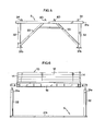
- Figs 5 and 6 show a first variant where all the vertical supports 32 are interconnected by means of horizontal elements 31 a and 31 b as well as oblique struts 33, so as to form a continuous placement frame S.
- the horizontal elements 31 a and 31 b have no load-carrying function but merely serve to maintain the vertical supports 32 upright and at a predetermined mutual distance before the container 10 is placed on the frame S.
- each vertical support 32 consists of a separate support leg.
- each separate support leg 32 has two handles 35 for manually handling the support legs.
- Fig. 8 schematically illustrates at 37 a vertical surface which is disposed, for example, immediately behind the driver's cabin on a transport vehicle, on which containers according to Fig. 1 are to be carried. At the lower end of the surface 37, two apertured holders 39 are provided, in which the individual support legs 32 can be placed and stored on the vehicle.
- this can be detachably connected to the free end 30 of the projecting arm 18 in order, together with the arm 18, to form a stable right-angled joint.
- This stable, yet dividable joint is achieved according to the invention by means of a cone joint having a vertical centre axis C and comprising a male member 34 and a female member 36.
- the male members 34 preferably are arranged on the vertical supports 32 while the female members 36 are arranged in the ends 30 of the arms 18 projecting from the container 10.
- the male member 34 is in the form of an upwardly directed, straight, cylindrical truncated cone, half the vertex angle of which is about 10 ° in the illustrated example.
- the female member 36 is in the form of a downwardly divergent cone which is open at the bottom and has a vertex angle matching that of the male member 34.
- the two parts 34 and 36 are made of a hard material, such as steel.
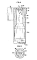
- the support leg 32 shown in Fig. 9 consists of a relatively light aluminium tube 32a which extends throughout substantially the entire height of the support leg and which at the top supports a relatively short male insert 32b of steel, which is cylindrical at the bottom.
- the vertex angle of cone joint exceeds the locking angle, i.e. exceeds the angle which would have brought about mutual locking of the male and female members when subjected to load.
- the joint is stable, i.e. that the right angle between the arm 18 and the vertical support 32 is safely maintained upon loading and also if the container 10, when in its position of placement, is subjected to lateral forces.
- the conicity of the parts 34 and 36 contributes to facilitate positioning the male member 34 in the female member 36, especially in the embodiment of Figs 5 and 6, where the load carrier 10 is to be lowered on to a frame S already in place, it should be emphasised that the primary purpose of the cone joint is not to facilitate positioning but to provide a joint between the arm 18 and the vertical support 32 which is completely stable when subjected to load. In the position of placement, the female member 36 is resting directly on the male member 34. The greater the load, the more stable the joint.
- the device according to the invention is preferably provided with locking means making it possible to temporarily lock the cone joint 32, 34. It thus becomes possible to lift the load carrier or the container 10, extend the arms 18, lift the support legs 32 one at a time and fit the male member 34 into the corresponding female member 36, whereupon this support leg 32 is locked to the arm 18 with the aid of the above-mentioned locking means before the next support leg 32 is mounted. When all the support legs 32 are thus mounted, the container 10 can be lowered.
- the locking means do not contribute to the stability of the cone joint, which is achieved only by the mutual engagement between the male and female members.
- the locking means can be designed in many different ways, the embodiment shown in Figs 9 and 10 being only one among several conceivable alternatives.
- the male member 34 is provided with a horizontal, circular top plate 42 fitted in an internal cylindrical channel 43 of the male insert 32b.
- the top plate 42 has a rectangular through groove or slot 44 and a fixed pin 46 projecting downwards from its underside (not shown in Fig. 9).
- the female member 36 is provided with a downwardly directed locking member 48 which matches the groove 44 and substantially is in the form of a flat arrow rigidly connected to the arm 18. As seen from the top view of Fig.
- the locking member 48 can be inserted unimpededly through the slot 44 of the top plate 42 when the support leg 32 is lifted up towards the arm 18, whereupon the support leg 32 can be rotated 90 ° about the centre axis C of the cone joint until the locking member 48 is brought into abutment against the pin 46, as indicated by dash-dot lines in Fig. 10.
- the male member 34 is prevented from leaving the female member 36, and it is understood that if the container 10 with the thus- locked support legs 32 is held in a raised position, then each support leg 32 will rest via its top plate 44 on the locking member 48.
- Fig. 9 shows an instance where the container is in its position of placement with the male member 34 and the female member 36 engaging each other.
- Placement frames according to the principle in Figs 5 and 6 are especially usable on placement surfaces which are frequently used for accommodating load carriers 10. Several such frames can then be interconnected, if desired.
- One advantage of this frame design, as compared with separate support legs according to Figs 7-10, is that the horizontal element 31 a, combined with the diagonal struts 33, improves the stability of the device against tilting in the direction of the element 31a. This is advantageous, for example, if a vehicle is to be reversed in underneath in load carrier 10 between the vertical supports 32.
- Fig. 6 shows how a container according to Figs 1 and 2 is brought into position, for instance, by means of a fork-lift truck (not shown) with its arms 18 extended, on the frame S composed of four vertical supports 32.
- the frame S in Figs 5 and 6 can also be used for narrower containers whose width, and hence the distance between the arms 18, is substantially half the width of the container 10 of Fig. 2.
- the frame in Figs 5 and 6 is provided with extra male members 40, such that the frame can simultaneously carry two such narrower containers beside each other.
- the parts of the coin joint may change places, so that the male member is arranged on the arm and the female member on the vertical support, although the variant illustrated in the drawings is preferable.
- the arm may execute a non-linear movement instead of a linear one, for example a horizontal outward pivotal movement from a transport position parallel to the corresponding side of the load carrier to a swung-out operative position.
Landscapes
- Engineering & Computer Science (AREA)
- Mechanical Engineering (AREA)
- Forklifts And Lifting Vehicles (AREA)
- Crushing And Grinding (AREA)
- Polarising Elements (AREA)
- Handcart (AREA)
- Fittings On The Vehicle Exterior For Carrying Loads, And Devices For Holding Or Mounting Articles (AREA)
- Pallets (AREA)
Priority Applications (3)
| Application Number | Priority Date | Filing Date | Title |
|---|---|---|---|
| EP94200379A EP0667307B1 (fr) | 1994-02-14 | 1994-02-14 | Appareil pour la pose des porte-charges |
| AT94200379T ATE158254T1 (de) | 1994-02-14 | 1994-02-14 | Vorrichtung zum aufsetzen von lastträgern |
| DE69405704T DE69405704T2 (de) | 1994-02-14 | 1994-02-14 | Vorrichtung zum Aufsetzen von Lastträgern |
Applications Claiming Priority (1)
| Application Number | Priority Date | Filing Date | Title |
|---|---|---|---|
| EP94200379A EP0667307B1 (fr) | 1994-02-14 | 1994-02-14 | Appareil pour la pose des porte-charges |
Publications (2)
| Publication Number | Publication Date |
|---|---|
| EP0667307A1 true EP0667307A1 (fr) | 1995-08-16 |
| EP0667307B1 EP0667307B1 (fr) | 1997-09-17 |
Family
ID=8216643
Family Applications (1)
| Application Number | Title | Priority Date | Filing Date |
|---|---|---|---|
| EP94200379A Expired - Lifetime EP0667307B1 (fr) | 1994-02-14 | 1994-02-14 | Appareil pour la pose des porte-charges |
Country Status (3)
| Country | Link |
|---|---|
| EP (1) | EP0667307B1 (fr) |
| AT (1) | ATE158254T1 (fr) |
| DE (1) | DE69405704T2 (fr) |
Cited By (2)
| Publication number | Priority date | Publication date | Assignee | Title |
|---|---|---|---|---|
| WO1997030615A1 (fr) * | 1996-02-22 | 1997-08-28 | Fehlbaum & Co. | Plaque a montants pour presentation d'articles |
| CN113023146A (zh) * | 2019-12-24 | 2021-06-25 | 南通中集特种运输设备制造有限公司 | 具有外挂设备的集装箱 |
Citations (4)
| Publication number | Priority date | Publication date | Assignee | Title |
|---|---|---|---|---|
| DE840527C (de) * | 1949-12-03 | 1952-06-03 | Emil Otto | Verfahren und Vorrichtung zum Be- und Entladen von Lastkraftwagen |
| US3173562A (en) * | 1961-10-30 | 1965-03-16 | Gen Am Transport | Systems for transferring demountable freight containers between movable vehicles andexternal supports |
| FR2071371A5 (fr) * | 1969-12-24 | 1971-09-17 | Meilleurat Henri | |
| FR2497182A1 (fr) * | 1980-12-26 | 1982-07-02 | Marquet Jean Marie | Plate-forme de transport et de transfert de charges |
-
1994
- 1994-02-14 DE DE69405704T patent/DE69405704T2/de not_active Expired - Fee Related
- 1994-02-14 AT AT94200379T patent/ATE158254T1/de not_active IP Right Cessation
- 1994-02-14 EP EP94200379A patent/EP0667307B1/fr not_active Expired - Lifetime
Patent Citations (4)
| Publication number | Priority date | Publication date | Assignee | Title |
|---|---|---|---|---|
| DE840527C (de) * | 1949-12-03 | 1952-06-03 | Emil Otto | Verfahren und Vorrichtung zum Be- und Entladen von Lastkraftwagen |
| US3173562A (en) * | 1961-10-30 | 1965-03-16 | Gen Am Transport | Systems for transferring demountable freight containers between movable vehicles andexternal supports |
| FR2071371A5 (fr) * | 1969-12-24 | 1971-09-17 | Meilleurat Henri | |
| FR2497182A1 (fr) * | 1980-12-26 | 1982-07-02 | Marquet Jean Marie | Plate-forme de transport et de transfert de charges |
Cited By (3)
| Publication number | Priority date | Publication date | Assignee | Title |
|---|---|---|---|---|
| WO1997030615A1 (fr) * | 1996-02-22 | 1997-08-28 | Fehlbaum & Co. | Plaque a montants pour presentation d'articles |
| CN113023146A (zh) * | 2019-12-24 | 2021-06-25 | 南通中集特种运输设备制造有限公司 | 具有外挂设备的集装箱 |
| CN113023146B (zh) * | 2019-12-24 | 2024-11-05 | 南通中集特种运输设备制造有限公司 | 具有外挂设备的集装箱 |
Also Published As
| Publication number | Publication date |
|---|---|
| ATE158254T1 (de) | 1997-10-15 |
| DE69405704T2 (de) | 1998-03-12 |
| DE69405704D1 (de) | 1997-10-23 |
| EP0667307B1 (fr) | 1997-09-17 |
Similar Documents
| Publication | Publication Date | Title |
|---|---|---|
| US5106247A (en) | Automatic locking system | |
| US3664273A (en) | Load carrying stacking platforms | |
| US6957613B2 (en) | Airlift pallet for container roll-in/out platform (CROP) | |
| EP1513744B1 (fr) | Systeme de conteneur modulaire pour le transport aerien | |
| US5810186A (en) | Goods transporting platform | |
| EP1967466A1 (fr) | Conteneur de fret approprié pour le transport de bobines | |
| US11661269B2 (en) | Vehicle transport structures | |
| JP2002087150A (ja) | コンテナの荷役積載装置 | |
| US3420379A (en) | Load carrying device | |
| US4854807A (en) | Freight container lifting means | |
| CA2089685A1 (fr) | Cadre d'appui auxiliaire pour le chargement et le dechargement, a l'aide d'un appareil de manutention dote d'un bras de levage hydraulique, de marchandises destinees au transport | |
| JPS6253379B2 (fr) | ||
| US5924248A (en) | Collapsible frame device | |
| EP0667307B1 (fr) | Appareil pour la pose des porte-charges | |
| US7374193B2 (en) | Transporting apparatus and trailer conversion kit and method | |
| EP0597979B1 (fr) | Plate-forme de transport de marchandises | |
| GB2104875A (en) | Container handling device | |
| US7500683B2 (en) | Filing cabinet dolly | |
| CN211310699U (zh) | 用于提升和降低重物的设备 | |
| US20080190810A1 (en) | Collapsible Transport and Storage Container | |
| EP0163621A1 (fr) | Patte de support repliable et réglable pour châssis porte-charges | |
| JPH0924838A (ja) | 薄形矩形物等搬送方法およびその装置 | |
| US3734315A (en) | Means for transporting palletized loads | |
| GB2197296A (en) | Freight containers lifting means | |
| WO2003068616A1 (fr) | Plates-formes de transport de bobines |
Legal Events
| Date | Code | Title | Description |
|---|---|---|---|
| PUAI | Public reference made under article 153(3) epc to a published international application that has entered the european phase |
Free format text: ORIGINAL CODE: 0009012 |
|
| AK | Designated contracting states |
Kind code of ref document: A1 Designated state(s): AT CH DE FR LI NL |
|
| 17P | Request for examination filed |
Effective date: 19960214 |
|
| GRAG | Despatch of communication of intention to grant |
Free format text: ORIGINAL CODE: EPIDOS AGRA |
|
| 17Q | First examination report despatched |
Effective date: 19961218 |
|
| GRAH | Despatch of communication of intention to grant a patent |
Free format text: ORIGINAL CODE: EPIDOS IGRA |
|
| GRAH | Despatch of communication of intention to grant a patent |
Free format text: ORIGINAL CODE: EPIDOS IGRA |
|
| GRAA | (expected) grant |
Free format text: ORIGINAL CODE: 0009210 |
|
| AK | Designated contracting states |
Kind code of ref document: B1 Designated state(s): AT CH DE FR LI NL |
|
| PG25 | Lapsed in a contracting state [announced via postgrant information from national office to epo] |
Ref country code: NL Free format text: LAPSE BECAUSE OF FAILURE TO SUBMIT A TRANSLATION OF THE DESCRIPTION OR TO PAY THE FEE WITHIN THE PRESCRIBED TIME-LIMIT Effective date: 19970917 Ref country code: LI Effective date: 19970917 Ref country code: CH Effective date: 19970917 |
|
| REF | Corresponds to: |
Ref document number: 158254 Country of ref document: AT Date of ref document: 19971015 Kind code of ref document: T |
|
| REG | Reference to a national code |
Ref country code: CH Ref legal event code: EP |
|
| REF | Corresponds to: |
Ref document number: 69405704 Country of ref document: DE Date of ref document: 19971023 |
|
| ET | Fr: translation filed | ||
| PGFP | Annual fee paid to national office [announced via postgrant information from national office to epo] |
Ref country code: FR Payment date: 19980210 Year of fee payment: 5 Ref country code: AT Payment date: 19980210 Year of fee payment: 5 |
|
| NLV1 | Nl: lapsed or annulled due to failure to fulfill the requirements of art. 29p and 29m of the patents act | ||
| REG | Reference to a national code |
Ref country code: CH Ref legal event code: PL |
|
| PLBE | No opposition filed within time limit |
Free format text: ORIGINAL CODE: 0009261 |
|
| STAA | Information on the status of an ep patent application or granted ep patent |
Free format text: STATUS: NO OPPOSITION FILED WITHIN TIME LIMIT |
|
| 26N | No opposition filed | ||
| PG25 | Lapsed in a contracting state [announced via postgrant information from national office to epo] |
Ref country code: AT Free format text: LAPSE BECAUSE OF NON-PAYMENT OF DUE FEES Effective date: 19990214 |
|
| PG25 | Lapsed in a contracting state [announced via postgrant information from national office to epo] |
Ref country code: FR Free format text: LAPSE BECAUSE OF NON-PAYMENT OF DUE FEES Effective date: 19991029 |
|
| REG | Reference to a national code |
Ref country code: FR Ref legal event code: ST |
|
| PGFP | Annual fee paid to national office [announced via postgrant information from national office to epo] |
Ref country code: DE Payment date: 20030205 Year of fee payment: 10 |
|
| PG25 | Lapsed in a contracting state [announced via postgrant information from national office to epo] |
Ref country code: DE Free format text: LAPSE BECAUSE OF NON-PAYMENT OF DUE FEES Effective date: 20040901 |