EP0667986B1 - Dispositif permettant de proteger un onduleur - Google Patents
Dispositif permettant de proteger un onduleur Download PDFInfo
- Publication number
- EP0667986B1 EP0667986B1 EP94900003A EP94900003A EP0667986B1 EP 0667986 B1 EP0667986 B1 EP 0667986B1 EP 94900003 A EP94900003 A EP 94900003A EP 94900003 A EP94900003 A EP 94900003A EP 0667986 B1 EP0667986 B1 EP 0667986B1
- Authority
- EP
- European Patent Office
- Prior art keywords
- inverter
- semiconductor switch
- voltage
- diode
- arrangement
- Prior art date
- Legal status (The legal status is an assumption and is not a legal conclusion. Google has not performed a legal analysis and makes no representation as to the accuracy of the status listed.)
- Expired - Lifetime
Links
- 239000004065 semiconductor Substances 0.000 claims abstract description 21
- 239000003990 capacitor Substances 0.000 claims abstract description 7
- 230000000903 blocking effect Effects 0.000 claims abstract 2
- 230000001788 irregular Effects 0.000 claims description 3
- 238000011084 recovery Methods 0.000 abstract 2
- 230000001172 regenerating effect Effects 0.000 description 3
- 230000006378 damage Effects 0.000 description 1
- 230000007423 decrease Effects 0.000 description 1
- 230000002950 deficient Effects 0.000 description 1
- 238000012423 maintenance Methods 0.000 description 1
- 238000012544 monitoring process Methods 0.000 description 1
- 238000011144 upstream manufacturing Methods 0.000 description 1
Images
Classifications
-
- H—ELECTRICITY
- H02—GENERATION; CONVERSION OR DISTRIBUTION OF ELECTRIC POWER
- H02H—EMERGENCY PROTECTIVE CIRCUIT ARRANGEMENTS
- H02H7/00—Emergency protective circuit arrangements specially adapted for specific types of electric machines or apparatus or for sectionalised protection of cable or line systems, and effecting automatic switching in the event of an undesired change from normal working conditions
- H02H7/10—Emergency protective circuit arrangements specially adapted for specific types of electric machines or apparatus or for sectionalised protection of cable or line systems, and effecting automatic switching in the event of an undesired change from normal working conditions for converters; for rectifiers
- H02H7/12—Emergency protective circuit arrangements specially adapted for specific types of electric machines or apparatus or for sectionalised protection of cable or line systems, and effecting automatic switching in the event of an undesired change from normal working conditions for converters; for rectifiers for static converters or rectifiers
- H02H7/122—Emergency protective circuit arrangements specially adapted for specific types of electric machines or apparatus or for sectionalised protection of cable or line systems, and effecting automatic switching in the event of an undesired change from normal working conditions for converters; for rectifiers for static converters or rectifiers for inverters, i.e. DC/AC converters
- H02H7/1222—Emergency protective circuit arrangements specially adapted for specific types of electric machines or apparatus or for sectionalised protection of cable or line systems, and effecting automatic switching in the event of an undesired change from normal working conditions for converters; for rectifiers for static converters or rectifiers for inverters, i.e. DC/AC converters responsive to abnormalities in the input circuit, e.g. transients in the DC input
Definitions
- the invention relates to an arrangement in an inverter, preferably a pulse-controlled inverter, which is connected on the input side to a DC voltage and feeds an AC motor, in particular an asynchronous motor, the arrangement being looped in between a line reactor and a parallel capacitor at the input of the inverter.
- an inverter preferably a pulse-controlled inverter
- Such an arrangement is known from AT-A-329 659.
- tram networks With tram networks, it is common to divide them into individual supply sections. It can therefore happen that a tram set enters a short-circuit section, e.g. in the event of a public transport accident, the corresponding section is grounded and there is a possibility that the subsequent train set will enter the grounded section.
- individual sections of the route are often grounded for safety, although entry into this section of the route with a bracket attached cannot be ruled out. Without suitable measures, an inadmissibly high feedback current (I R ) would flow in this fault case, which would lead to the destruction of the semiconductor valves of the inverter. A number of measures are conceivable to control this error.
- the task now is to create an arrangement with which earth or short circuits in the supply network can be optimally controlled.
- the invention is characterized in that the arrangement of a freewheeling diode in the reverse direction, which is connected to the DC voltage, and an anti-parallel circuit consisting of a semiconductor switch, in particular a thyristor (GTO) that can be switched off, and a diode which is connected to the positive DC voltage line is connected, wherein the cathode of the freewheeling diode is connected on the one hand to the anode of the diode and on the other hand to the emitter or the cathode of the semiconductor switch, and that a current and a voltage measuring element is provided which recognize an input short circuit in which the Semiconductor switch is blocked. This ensures that excessive currents do not occur in the semiconductors of the inverter.
- GTO thyristor
- the semiconductor switch In the event of a fault, the semiconductor switch is blocked and the freewheeling diode takes over the mains current.
- the diode of the anti-parallel circuit is arranged so that this diode conducts when power is drawn from the DC voltage network.
- current only flows through the semiconductor switch when energy is fed back into the network.
- the parallel or Backup capacitor If the inverter is not quickly disconnected from the grid in the event of a grid short circuit, the parallel or Backup capacitor. This affects the AC motor like a terminal short circuit.
- a control is provided for the semiconductor switch, which blocks the semiconductor switch in the event of an irregular voltage drop and / or an increase in the feedback current to impermissibly high values.
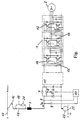
- the drawing shows a three-phase inverter 1 with an upstream brake actuator 11.
- a parallel capacitor 4 or backup capacitor is provided at the input of the brake actuator 11.
- the inverter 1, which feeds the asynchronous motor 2, consists of six transistors 12, each of which a freewheeling diode 13 is assigned in parallel. Each transistor 12 is connected to a control 14, the two controls 14 for the transistors 12 of one phase being connected to monitoring electronics 15. The currents and voltages in the feed lines to the asynchronous motor 2 are detected and fed to a control, not shown, which is also connected to the controls 14.
- the arrangement according to the invention is connected between a line choke 3 and a parallel capacitor 4.
- This consists of a freewheeling diode 5 in the reverse direction, which is connected to the DC voltage.
- An anti-parallel circuit consisting of a semiconductor switch 6, in this case a thyristor (GTO) which can be switched off, and a diode 7 is connected to the positive DC voltage line.
- the cathode of the freewheeling diode 5 is connected to the anode of the diode 7 and to the cathode of the thyristor 6 which can be switched off.
- Furthermore there are a current 8 and a Voltage measuring element 9 is provided which detects an input short circuit in which the thyristor 6 which can be switched off is blocked.
- a control 10 is provided for the thyristor 6 which can be switched off, to which the current 8 and the voltage measuring element 9 are connected and which blocks the thyristor 6 in the event of an irregular voltage drop and / or an increase in the feedback current I R to inadmissibly high values.
- the regenerative current I R always flows in the direction shown.
- the illustration shown in the figure is a drive for a rail vehicle, for example a tram.
- the line choke 3 is connected here with a connection via a current collector 16 and a switch 18 to the overhead line 17, which is the positive pole of the DC supply voltage.
- a second switch 19 with a charging resistor 20 is connected in series.
- the negative pole of the DC voltage is the rail 21 of the tram, which has earth potential, the connection with the brake actuator 11 and the inverter 1 being established via the wheels 22 of the rail vehicle.
- the semiconductor diodes of the brake actuator 11 are likewise not loaded with impermissibly high currents by the arrangement according to the invention in the event of a short circuit.
- the thyristor 6 that can be switched off is always conductive.
Landscapes
- Engineering & Computer Science (AREA)
- Power Engineering (AREA)
- Inverter Devices (AREA)
- Emergency Protection Circuit Devices (AREA)
- Control Of Electric Motors In General (AREA)
- Control Of Ac Motors In General (AREA)
- Control Of Motors That Do Not Use Commutators (AREA)
- Stopping Of Electric Motors (AREA)
Claims (2)
- Dispositif prévu pour un onduleur (1), de préférence un onduleur à impulsions, raccordé côté entrée à une tension continue et alimentant un moteur à courant alternatif, en particulier un moteur asynchrone, le dispositif étant branché en boucle entre une bobine d'arrêt (3) et un condensateur parallèle (4), à l'entrée de l'onduleur (1), caractérisé en ce que le dispositif est constitué d'une diode de roue libre (5) dans la direction de blocage, placée sous l'effet de la tension continue, et d'un branchement antiparallèle constitué d'un commutateur à semi-conducteur (6), en particulier d'un thyristor déconnectable (GTO) et d'une diode (7), branchée dans la ligne positive de la tension continue, la cathode de la diode à roue libre (5) étant reliée, d'une part, à l'anode de la diode (7) et, d'autre part, à l'émetteur, respectivement à la cathode du commutateur à semi-conducteur (8), et en ce qu'un organe de mesure d'intensité (8) et un organe de mesure de tension (9) sont prévus, qui identifient un court-circuit à l'entrée, pour lequel le commutateur à semi-conducteur (6) est bloqué.
- Dispositif selon la revendication 1, caractérisé en ce qu'est prévue pour le commutateur à semi-conducteur (6), une commande (10) qui, en cas d'apparition d'irrégularités de tension et/ou d'une augmentation du courant d'alimentation de retour (IR) ayant des valeurs inadmissibles, bloque le commutateur à semi-conducteur (6).
Applications Claiming Priority (3)
| Application Number | Priority Date | Filing Date | Title |
|---|---|---|---|
| AT0217592A AT400991B (de) | 1992-11-04 | 1992-11-04 | Vorrichtung zum schutz eines wechselrichters |
| AT2175/92 | 1992-11-04 | ||
| PCT/AT1993/000170 WO1994010733A1 (fr) | 1992-11-04 | 1993-11-04 | Dispositif permettant de proteger un onduleur |
Publications (2)
| Publication Number | Publication Date |
|---|---|
| EP0667986A1 EP0667986A1 (fr) | 1995-08-23 |
| EP0667986B1 true EP0667986B1 (fr) | 1997-03-05 |
Family
ID=3529337
Family Applications (1)
| Application Number | Title | Priority Date | Filing Date |
|---|---|---|---|
| EP94900003A Expired - Lifetime EP0667986B1 (fr) | 1992-11-04 | 1993-11-04 | Dispositif permettant de proteger un onduleur |
Country Status (5)
| Country | Link |
|---|---|
| EP (1) | EP0667986B1 (fr) |
| AT (2) | AT400991B (fr) |
| DE (1) | DE59305661D1 (fr) |
| GR (1) | GR3023388T3 (fr) |
| WO (1) | WO1994010733A1 (fr) |
Families Citing this family (2)
| Publication number | Priority date | Publication date | Assignee | Title |
|---|---|---|---|---|
| US3980010A (en) * | 1974-09-18 | 1976-09-14 | Luigi Collinucci | Cooking spit |
| RU2119707C1 (ru) * | 1996-09-17 | 1998-09-27 | Акционерное общество открытого типа "Научно-исследовательский институт по передаче электроэнергии постоянным током высокого напряжения" | Устройство защиты автономного инвертора на запираемых тиристорах от однофазного опрокидывания |
Family Cites Families (2)
| Publication number | Priority date | Publication date | Assignee | Title |
|---|---|---|---|---|
| DE2349161C3 (de) * | 1973-09-29 | 1978-09-21 | Brown, Boveri & Cie Ag, 6800 Mannheim | Anordnung zum Schutz eines von einem Gleichspannungszwischenkreis gespeisten selbstgeführten Wechselrichters |
| DE4115856A1 (de) * | 1991-05-15 | 1992-11-19 | Abb Patent Gmbh | Verfahren und vorrichtung zum abschalten eines ueberstromes bei einem wechselrichter |
-
1992
- 1992-11-04 AT AT0217592A patent/AT400991B/de not_active IP Right Cessation
-
1993
- 1993-11-04 DE DE59305661T patent/DE59305661D1/de not_active Expired - Lifetime
- 1993-11-04 AT AT94900003T patent/ATE149757T1/de active
- 1993-11-04 EP EP94900003A patent/EP0667986B1/fr not_active Expired - Lifetime
- 1993-11-04 WO PCT/AT1993/000170 patent/WO1994010733A1/fr not_active Ceased
-
1997
- 1997-05-09 GR GR970401041T patent/GR3023388T3/el unknown
Also Published As
| Publication number | Publication date |
|---|---|
| AT400991B (de) | 1996-05-28 |
| GR3023388T3 (en) | 1997-08-29 |
| WO1994010733A1 (fr) | 1994-05-11 |
| ATE149757T1 (de) | 1997-03-15 |
| EP0667986A1 (fr) | 1995-08-23 |
| DE59305661D1 (de) | 1997-04-10 |
| ATA217592A (de) | 1995-09-15 |
Similar Documents
| Publication | Publication Date | Title |
|---|---|---|
| EP1917706B1 (fr) | Montage convertisseur comprenant des accumulateurs d'energie repartis | |
| DE112017007140T5 (de) | Halbleitervorrichtung und Leistungsumwandlungssystem | |
| WO2010025758A1 (fr) | Dispositif présentant un convertisseur de fréquence | |
| DE112017000253T5 (de) | Leistungsumwandlungsvorrichtung | |
| DE102012024728A1 (de) | Verfahren und Vorrichtung zur Überwachung einer elektrischen Anlage auf einen Rückstrom | |
| EP0706218A2 (fr) | Procédé pour éliminer des erreurs dans un dispositif de ciruit rédresseur | |
| WO2019170475A1 (fr) | Dispositif de charge à courant alternatif pour un véhicule à moteur et procédé pour faire fonctionner un dispositif de charge à courant alternatif pour un véhicule à moteur | |
| DE3688347T2 (de) | Leistungsversorgungseinrichtung fuer elektrische gleichstromeisenbahn. | |
| DE3032328A1 (de) | Ueberstromschutzschaltung | |
| EP3652849B1 (fr) | Couplage de circuit intermédiaire dans des groupes d'entraînement | |
| EP0667986B1 (fr) | Dispositif permettant de proteger un onduleur | |
| DE2223828C3 (de) | Überstromschutzanordnung | |
| DE10146868A1 (de) | Schaltungsanordnung zum Vorladen eines stromrichtergespeisten Kondensators | |
| EP2220738B1 (fr) | Système d'entraînement et procédé de commande correspondant | |
| EP1782527A1 (fr) | Dispositif d'alimentation de groupes auxiliaires destines a un vehicule a entrainement electrothermique | |
| EP4652061A1 (fr) | Protection contre les courts-circuits au moyen d'un commutateur à semi-conducteurs | |
| DE19833551A1 (de) | Stromversorgungseinrichtung für eine Last | |
| WO2019042566A1 (fr) | Ensemble convertisseur | |
| EP3804112A1 (fr) | Convertisseur modulaire multiniveau présentant différents types de sous-module | |
| DE19833490C2 (de) | Spannungszwischenkreisumrichter | |
| DE2831495A1 (de) | Ueberstromschutz fuer einen zwischenkreisumrichter oder selbstgefuehrten wechselrichter | |
| EP0332974A1 (fr) | Protection contre les court-circuits pour un convertisseur d'impulsions alimentant une macine électriqe utilisée aussi bien en génératrice qu'en réceptrice | |
| EP0592696A1 (fr) | Circuit de protection pour une branche d'onduleur | |
| DE102022208424B3 (de) | Elektrische Schaltung zur Unterbrechung eines Stromkreises und Verfahren zum Betreiben eines Hochvolt-Gleichspannungsnetzes mit der Schaltung | |
| DE4126816C2 (de) | Schaltungsanordnung für ein Gleichrichter-Unterwerk |
Legal Events
| Date | Code | Title | Description |
|---|---|---|---|
| PUAI | Public reference made under article 153(3) epc to a published international application that has entered the european phase |
Free format text: ORIGINAL CODE: 0009012 |
|
| 17P | Request for examination filed |
Effective date: 19950420 |
|
| AK | Designated contracting states |
Kind code of ref document: A1 Designated state(s): AT BE CH DE DK ES FR GB GR IT LI NL SE |
|
| GRAG | Despatch of communication of intention to grant |
Free format text: ORIGINAL CODE: EPIDOS AGRA |
|
| 17Q | First examination report despatched |
Effective date: 19960131 |
|
| GRAH | Despatch of communication of intention to grant a patent |
Free format text: ORIGINAL CODE: EPIDOS IGRA |
|
| GRAH | Despatch of communication of intention to grant a patent |
Free format text: ORIGINAL CODE: EPIDOS IGRA |
|
| GRAA | (expected) grant |
Free format text: ORIGINAL CODE: 0009210 |
|
| AK | Designated contracting states |
Kind code of ref document: B1 Designated state(s): AT BE CH DE DK ES FR GB GR IT LI NL SE |
|
| PG25 | Lapsed in a contracting state [announced via postgrant information from national office to epo] |
Ref country code: NL Free format text: LAPSE BECAUSE OF FAILURE TO SUBMIT A TRANSLATION OF THE DESCRIPTION OR TO PAY THE FEE WITHIN THE PRESCRIBED TIME-LIMIT Effective date: 19970305 Ref country code: IT Free format text: LAPSE BECAUSE OF FAILURE TO SUBMIT A TRANSLATION OF THE DESCRIPTION OR TO PAY THE FEE WITHIN THE PRE;WARNING: LAPSES OF ITALIAN PATENTS WITH EFFECTIVE DATE BEFORE 2007 MAY HAVE OCCURRED AT ANY TIME BEFORE 2007. THE CORRECT EFFECTIVE DATE MAY BE DIFFERENT FROM THE ONE RECORDED.SCRIBED TIME-LIMIT Effective date: 19970305 Ref country code: ES Free format text: THE PATENT HAS BEEN ANNULLED BY A DECISION OF A NATIONAL AUTHORITY Effective date: 19970305 Ref country code: DK Effective date: 19970305 |
|
| REF | Corresponds to: |
Ref document number: 149757 Country of ref document: AT Date of ref document: 19970315 Kind code of ref document: T |
|
| REG | Reference to a national code |
Ref country code: CH Ref legal event code: EP |
|
| REF | Corresponds to: |
Ref document number: 59305661 Country of ref document: DE Date of ref document: 19970410 |
|
| GBT | Gb: translation of ep patent filed (gb section 77(6)(a)/1977) |
Effective date: 19970425 |
|
| PG25 | Lapsed in a contracting state [announced via postgrant information from national office to epo] |
Ref country code: SE Effective date: 19970605 |
|
| ET | Fr: translation filed | ||
| REG | Reference to a national code |
Ref country code: GR Ref legal event code: FG4A Free format text: 3023388 |
|
| NLV1 | Nl: lapsed or annulled due to failure to fulfill the requirements of art. 29p and 29m of the patents act | ||
| PLBE | No opposition filed within time limit |
Free format text: ORIGINAL CODE: 0009261 |
|
| STAA | Information on the status of an ep patent application or granted ep patent |
Free format text: STATUS: NO OPPOSITION FILED WITHIN TIME LIMIT |
|
| 26N | No opposition filed | ||
| REG | Reference to a national code |
Ref country code: GB Ref legal event code: IF02 |
|
| REG | Reference to a national code |
Ref country code: DE Ref legal event code: R081 Ref document number: 59305661 Country of ref document: DE Owner name: ELIN EBG TRACTION GMBH, AT Free format text: FORMER OWNER: ELIN ENERGIEANWENDUNG GES.M.B.H., WIEN, AT Effective date: 20111128 |
|
| REG | Reference to a national code |
Ref country code: AT Ref legal event code: PC Ref document number: 149757 Country of ref document: AT Kind code of ref document: T Owner name: SIEMENS AG OESTERREICH, AT Effective date: 20120419 |
|
| PGFP | Annual fee paid to national office [announced via postgrant information from national office to epo] |
Ref country code: GR Payment date: 20121112 Year of fee payment: 20 Ref country code: GB Payment date: 20121115 Year of fee payment: 20 |
|
| PGFP | Annual fee paid to national office [announced via postgrant information from national office to epo] |
Ref country code: FR Payment date: 20121214 Year of fee payment: 20 Ref country code: AT Payment date: 20121010 Year of fee payment: 20 |
|
| PGFP | Annual fee paid to national office [announced via postgrant information from national office to epo] |
Ref country code: BE Payment date: 20121217 Year of fee payment: 20 Ref country code: DE Payment date: 20130118 Year of fee payment: 20 Ref country code: CH Payment date: 20130211 Year of fee payment: 20 |
|
| REG | Reference to a national code |
Ref country code: DE Ref legal event code: R071 Ref document number: 59305661 Country of ref document: DE |
|
| REG | Reference to a national code |
Ref country code: DE Ref legal event code: R071 Ref document number: 59305661 Country of ref document: DE |
|
| REG | Reference to a national code |
Ref country code: CH Ref legal event code: PL |
|
| REG | Reference to a national code |
Ref country code: GB Ref legal event code: PE20 Expiry date: 20131103 |
|
| BE20 | Be: patent expired |
Owner name: *ELIN ENERGIEANWENDUNG G.M.B.H. Effective date: 20131104 |
|
| REG | Reference to a national code |
Ref country code: AT Ref legal event code: MK07 Ref document number: 149757 Country of ref document: AT Kind code of ref document: T Effective date: 20131104 |
|
| PG25 | Lapsed in a contracting state [announced via postgrant information from national office to epo] |
Ref country code: DE Free format text: LAPSE BECAUSE OF EXPIRATION OF PROTECTION Effective date: 20131105 Ref country code: GB Free format text: LAPSE BECAUSE OF EXPIRATION OF PROTECTION Effective date: 20131103 |
|
| REG | Reference to a national code |
Ref country code: GR Ref legal event code: MA Ref document number: 970401041 Country of ref document: GR Effective date: 20131105 |