EP0668487B1 - Compteur d'eau composé - Google Patents
Compteur d'eau composé Download PDFInfo
- Publication number
- EP0668487B1 EP0668487B1 EP94102381A EP94102381A EP0668487B1 EP 0668487 B1 EP0668487 B1 EP 0668487B1 EP 94102381 A EP94102381 A EP 94102381A EP 94102381 A EP94102381 A EP 94102381A EP 0668487 B1 EP0668487 B1 EP 0668487B1
- Authority
- EP
- European Patent Office
- Prior art keywords
- shut
- valve
- water meter
- composite water
- auxiliary
- Prior art date
- Legal status (The legal status is an assumption and is not a legal conclusion. Google has not performed a legal analysis and makes no representation as to the accuracy of the status listed.)
- Expired - Lifetime
Links
- XLYOFNOQVPJJNP-UHFFFAOYSA-N water Substances O XLYOFNOQVPJJNP-UHFFFAOYSA-N 0.000 title claims description 34
- 150000001875 compounds Chemical class 0.000 title description 8
- 238000007789 sealing Methods 0.000 claims description 21
- 239000002131 composite material Substances 0.000 claims description 13
- 230000004888 barrier function Effects 0.000 claims description 4
- 238000011144 upstream manufacturing Methods 0.000 claims description 4
- 239000000463 material Substances 0.000 claims 1
- 229920003023 plastic Polymers 0.000 claims 1
- 239000004033 plastic Substances 0.000 claims 1
- 230000006835 compression Effects 0.000 description 7
- 238000007906 compression Methods 0.000 description 7
- 238000005259 measurement Methods 0.000 description 7
- 230000007935 neutral effect Effects 0.000 description 5
- 238000010276 construction Methods 0.000 description 3
- 238000000034 method Methods 0.000 description 3
- 230000008569 process Effects 0.000 description 3
- 230000000694 effects Effects 0.000 description 2
- JEIPFZHSYJVQDO-UHFFFAOYSA-N iron(III) oxide Inorganic materials O=[Fe]O[Fe]=O JEIPFZHSYJVQDO-UHFFFAOYSA-N 0.000 description 2
- 230000009467 reduction Effects 0.000 description 2
- 235000008733 Citrus aurantifolia Nutrition 0.000 description 1
- 235000011941 Tilia x europaea Nutrition 0.000 description 1
- 230000033228 biological regulation Effects 0.000 description 1
- 230000008859 change Effects 0.000 description 1
- 230000003247 decreasing effect Effects 0.000 description 1
- 230000005484 gravity Effects 0.000 description 1
- 238000002347 injection Methods 0.000 description 1
- 239000007924 injection Substances 0.000 description 1
- 239000004571 lime Substances 0.000 description 1
- 239000002245 particle Substances 0.000 description 1
- 238000010079 rubber tapping Methods 0.000 description 1
- 230000001960 triggered effect Effects 0.000 description 1
- 238000005303 weighing Methods 0.000 description 1
Images


Classifications
-
- G—PHYSICS
- G01—MEASURING; TESTING
- G01F—MEASURING VOLUME, VOLUME FLOW, MASS FLOW OR LIQUID LEVEL; METERING BY VOLUME
- G01F7/00—Volume-flow measuring devices with two or more measuring ranges; Compound meters
Definitions
- the invention relates to a composite water meter Main counter for measuring the larger flows, one automatically acting changeover valve arranged behind, one sitting in a secondary line or a secondary channel Auxiliary meter for measuring the smaller flows and an exit of branch line or branch duct, the side opens into the housing of the changeover valve, according to Preamble of claim 1.
- DE-A-39 29 381 is a changeover valve for Compound water meter reveals which a permanent magnet used to a in the closed position of the valve plate exert additional holding force on this. This can the return spring is correspondingly weaker and / or shorter be made.
- This changeover valve also has a Lip seal that at the beginning of the opening stroke of the Valve plates initially "stick" to the sealing seat and only breaks off when the holding effect of the permanent magnet is overcome.
- the use of permanent magnets in Switching valves is used by most users rejected because it is feared that floating in the water Rust particles are attracted and disrupt the function. Also has been shown that the lip seal in connection with the protruding edge of the valve plate an additional Thrust in the opening direction is generated by a reinforced Magnetic and / or spring force must be compensated.
- the present invention has for its object a Specify compound counters of the type mentioned at the beginning, so is constructed that all the valve disc in Hydraulic and other forces reduced to a minimum or entirely are eliminated so that the valve plate in Spring holding the closing position minimally weak and / or short can be.
- the strong narrowing of the main flow sealing seat it works only a small opening pressure on the shut-off device, which the Allows use of the weak or short spring.
- the with such a strong narrowing of the Flow cross-section usually connected high Pressure loss is caused by the long inlet funnel avoided.
- Due to the conically narrowing downstream Annular chamber jacket is also ensured that the on Shutoff acting flow forces after opening the Main flow passage continuously increase, so that the Edge of the shut-off device suddenly the barrage overcomes while closing the Main flow passage and after overcoming the barrage also decrease continuously so that the shut-off device abruptly closes.
- shut-off Ring chamber at the secondary flow in the receiving the shut-off Ring chamber is initiated, so the introduction takes place via Control slots in a separate slot zone, which is between the cylindrical zone and the conical zone of the Annular chamber is located. This ensures that the the shut-off element triggered by the bypass flow forces only act in the opening direction when this completed a defined initial stroke and the Differential water pressure a certain minimum value has exceeded.
- a control valve in the secondary line or in the secondary duct which throttles the sidestream as soon as the Flow rate exceeds a certain level.
- a pressure surge is exerted on the shut-off element, which Edge of the shut-off device through the cylindrical zone of the Ring chamber pushes into its conical zone, whereupon the Flow forces the shut-off device as already described suddenly postpone.
- Fig. 1 shows schematically a compound water meter, in essentially consisting of a main counter 1, a Sub-counter 3 and a secondary line 2, the output 6 in the housing 5 of a changeover valve 4 opens. All parts are screwed together and mutually sealed. The extremely short overall length of the changeover valve is striking 4th
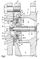
- Fig. 2 shows a longitudinal section on an enlarged scale by a first changeover valve 4.
- This has a Valve housing 5 with inlet flange 37, outlet flange 38 and connecting piece 39 for the secondary line 2.
- the from Sub-meter 3 incoming water flows through a secondary channel 2 in a central annular channel 40 of the valve housing 5.
- a compact switch insert 7 with his Fadedring 42 out in a housing fitting 43 and by means of O-ring 44 sealed against the rear housing part 11 is.
- the switching insert 7 consists essentially of one Switch insert carrier 13, on the front part 46 of which a hub 30 is integrally formed, on which a central sliding pin 8th screwed or injection molded. Connect support ribs 47 the central hub 30 with an outer ring 48.
- a longitudinally movable shut-off element 9 On the Slide pin 8 is a longitudinally movable shut-off element 9 a lip seal 27, a preloaded compression spring 12 and a clamping nut 45. Furthermore, a seal 34 is provided, against which the shut-off device 9 bears.
- the outer part 28 of the lip seal 27 is on the plate edge 17th of the shut-off element 9 is trapped.
- the inner part 29 of the Lip seal 27 is closed when the valve is closed labyrinthine support 50 and the compression spring 12 firmly against a circular sealing edge 49 of the switch insert carrier 13 pressed.
- inlet funnel 23 In front of the sealing edge 49 there is an inlet funnel 23, which is as long and flat as possible to avoid the pressure loss the water when passing through the opposite Nominal cross section of the valve is very narrow - typical an area reduction of 30 to 40% - cross section of the Mainstream flow zone 22 suffers to reduce. At maximum water flow may be according to the calibration regulations of Do not exceed a pressure drop of 0.5 bar.
- the switch insert carrier 7 also has an annular chamber 15 with a cylindrical zone 14, a slot zone 51 and a downstream conical one Dam level 52.
- the plate-shaped edge 17 of the shut-off element 9 is free of force and contact when the valve is closed the cylindrical zone 14.
- the cylindrical zone 14 can therefore also be referred to as a neutral zone.
- shut-off device 9 For controlling the shut-off device 9 when opening and Closing the same are the outer edge 18 of the Plate rim 17, the slot zone 51, the conical barrage 52 and the lip seal 27 responsible. These work when opening the shut-off element 9 as follows:
- the water to be measured overflows the secondary line 2 is measured in the secondary counter 3 and then flows through the connecting piece 39 in the Annular channel 40 of the valve housing 5. From there it passes through the control slots 31 and the conical barrage 52 in the Rear part of housing 11. This creates a pressure drop of about 0.2 to 0.4 bar. There is a back space 11 in the housing lower pressure than in main meter 1. This Differential pressure acts on the sealing edge 49 sealed shut-off device 9 in the opening direction. The Compression spring 12 initially holds the shut-off element 9 closed.
- shut-off 9 begins to move against the force of the compression spring 12. That remains the elastic lip seal 27 is initially still closed.
- the plate rim 17 of the shut-off element 9 slides through the neutral zone 14 to approximately in the middle of the slot zone 51.
- the secondary flow detects the plate 17 and pushes him in the conical barrage 52.
- the narrow annular gap 20 between the rim of the plate 17 and Annular chamber jacket 19 continuously; therefore the In any case, beyond the end of the Barrage 52 pushed.
- the lip seal 27 breaks from the sealing edge 49 and the bulk of the water flows through the main counter 1 and Main flow flow zone 22. This opening process takes place very quickly, so that measurement errors do not occur.
- shut-off device becomes 9 of the water flowing through against the resistance of the Compression spring 12 on the sliding pin 8 further downstream pushed until it reaches its end position (Fig. 3).
- the changeover valve is closed in reverse Sequence. With a decrease in the main flow the shut-off element 9 slides through the closing force of the Compression spring 12 upstream from its end position until it arrives at the barrage 52. The shut-off device 9 remains here stand until the water flow drops so far that the Force of the compression spring 12 the backlog resistance of the hydraulic Can overcome rest. The shut-off device 9 then slides without Delay back to its closed position, the continuous expansion of the annular gap 20 the Closing movement accelerates. The main flow flow 22 is closed suddenly; the water just flows still by the secondary counter 3.
- FIG. 3 shows the switching insert 7 from FIG. 2 on an enlarged scale Scale and with the shut-off element open to the maximum 9. This rests with its hub 53 on the spring lock nut 45.
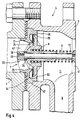
- Fig. 4 shows a longitudinal section through another Changeover valve 4.
- the outlet 6 of the secondary line opens here 2 behind the switching valve insert 7 in the valve housing 5.
- the outer ring 48 with the fitting ring 42 of the Switch insert carrier 13 were structurally changed.
- the for Opening and closing of the shut-off element 9 required control takes over here Conventional control valve arranged in the secondary line 2, which if exceeded a certain flow rate, the secondary line 2 throttles heavily.
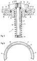
- Fig. 5 shows a modified switch insert 7, in which the main current flow zone 22 is sealed with an O-ring 26. This is fixed in an annular groove 54 clamped on the shut-off device 9. So that the shut-off device 9 has a certain initial stroke can run without the main flow passage being located at the end of the long inlet funnel 23 a cylindrical sealing seat passage 24. This should be as short as only remain possible so that the pressure loss in the strongly restricted main flow flow zone does not rise inadmissibly.
- the neutral zone is not cylindrical as on P. 5, lines 13, 14. Are covered by claim 1 exclusively Embodiments in which the neutral zone is cylindrical.
- Fig. 6 shows a section of a cross section along the line VI-VI 3 in the region of the slot zone 51.
- FIGS. 2, 4 and 5 are for the optimal functioning of the changeover valve 4 responsible characteristics together. It is the most constricted Main flow flow zone 22 to reduce the spring force or to shorten the Spring 12, the long inlet funnel 23 to reduce the pressure loss, the consequent avoidance of all further pressure and flow forces that are in the Activate neutral zone 14 located shutoff 9 in the opening direction could, and the conical barrage 52, which ensures that the shut-off 9 either only completely in the annular chamber 15 or only completely outside the same can.
- the sum of these features leads to an extremely short construction Switch valve 4, which has only a single sealing seat owns, is very simple, inexpensive and reliable, no tools or assistants to open and Closing required and any measurement errors in the switchover range reduced to an absolute minimum.
Landscapes
- Physics & Mathematics (AREA)
- Fluid Mechanics (AREA)
- General Physics & Mathematics (AREA)
- Measuring Volume Flow (AREA)
Claims (11)
- Compteur d'eau combiné comprenant un compteur principal (1) pour la mesure des débits importants, une vanne de commutation (4) disposée en aval, fonctionnant automatiquement et ne comportant pas de verrouillage magnétique, un compteur auxiliaire (3) pour la mesure des débits plus faibles, se trouvant dans une conduite auxiliaire (2) ou dans un canal auxiliaire, et une sortie (6) de la conduite auxiliaire (2) ou du canal auxiliaire, qui pénètre latéralement dans le carter (5) de la vanne de commutation (4), la vanne de commutation (4) comprenant une garniture complète de manoeuvre (7) se composant d'un support (13), d'un axe coulissant central (8) qui y est fixé, d'un élément de barrage (9) qui y est guidé de manière mobile et qui est actionné par un ressort (12) en direction de fermeture, d'un siège d'étanchéité pour le flux principal (49) qui est muni d'un joint souple (26, 27), dont le diamètre est rétréci et qui est disposé entre le support (13) et l'élément de barrage (9) et d'une chambre annulaire (15) recevant l'élément de barrage (9), qui est ouverte vers l'aval et qui se termine en un étage de retenue se rétrécissant en forme de cône (52), la vanne de commutation ne comportant, en dehors du siège d'étanchéité pour le flux principal, pas d'autre siège d'étanchéité non placé directement sur l'axe coulissant central et dans lequel il est prévu par ailleurs que la zone de passage du flux principal (22) de la garniture de manoeuvre (7) se compose d'un cône d'entrée (23) se rétrécissant vers l'aval avec à l'extrémité un siège d'étanchéité pour le flux principal (49) rétréci de 20 à 40% par rapport au diamètre nominal de la vanne, que le joint (26, 27) est fixé sur l'élément de barrage (9), que la chambre annulaire (15) comprend une zone cylindrique (14), que l'élément de barrage (9) possède un rebord plat (17) dont la partie frontale (16) se trouve, en position de fermeture, à l'intérieur de la zone cylindrique (14), sans être soumis à des efforts et à des contacts, et de ce fait en amont du flux et en dehors de la zone d'entrée du flux auxiliaire, les efforts hydrauliques produits par le flux auxiliaire n'agissant, en position de fermeture de la vanne, en aucun cas sur l'élément de barrage en direction d'ouverture, que l'enveloppe de la chambre annulaire (19) ne se rétrécit qu'au contact de la zone cylindrique (14), qu'il reste une étroite fente annulaire (20) entre le bord extérieur (18) du rebord plat (17) et l'enveloppe de la chambre annulaire (19) et que le rebord plat est poussé jusque derrière l'extrémité de l'étage de retenue lors de l'ouverture.
- Compteur d'eau combiné selon la revendication 1 caractérisé en ce que le support (13), l'enveloppe de la chambre annulaire (19) et l'étage de retenue (52) sont réalisés d'une seule pièce et sont en particulier fabriqués en plastique moulé par injection, et en ce que l'axe coulissant (8) est vissé ou moulé dans un moyeu (30) du support (13).
- Compteur d'eau combiné selon la revendication 1 ou 2, caractérisé en ce que des surfaces d'étanchéité placées sur l'axe coulissant central (8) et correspondant entre elles se trouvent aussi bien sur le coté arrière (32) du moyeu (30) du support (13) que sur le coté avant (33) de l'élément de barrage (9).
- Compteur d'eau combiné selon l'une des revendications 1 à 3, caractérisé en ce qu'un joint souple (34) est placé entre le coté arrière (32) du moyeu (30) du support (13) et le coté avant (33) de l'élément de barrage (9) sur l'axe coulissant (8).
- Compteur d'eau combiné selon l'une des revendications 1 à 4, caractérisé en ce qu'un court passage cylindrique du siège d'étanchéité (24) est prévu à l'extrémité du cône d'entrée (23) devant le siége d'étanchéité pour le flux principal (49).
- Compteur d'eau combiné selon la revendication 5, caractérisé en ce que l'élément de barrage (9) est muni sur son coté avant d'un joint torique (26) dont le diamètre extérieur assure l'étanchéité du passage du siège d'étanchéité (24) de façon telle que l'étanchéité est maintenue sur une longueur de course prédéterminée lors de l'ouverture de la vanne.
- Compteur d'eau combiné selon l'une des revendications 1 à 5, caractérisé en ce que l'élément de barrage (9) porte sur son coté avant un joint à lèvre de forme circulaire (27) dont le bord extérieur (28) est fixé de manière serrée sur l'élément de barrage (9) tandis que, lors de l'ouverture de la vanne, son bord intérieur (29) se déforme en direction axiale sur une longueur de course prédéterminée tout en maintenant l'étanchéité et en ce qu'une surface d'appui en forme de labyrinthe (50) est prévue sous le joint à lèvre (27).
- Compteur d'eau combiné selon l'une des revendications 1 à 7, caractérisé en ce que le support de garniture de manoeuvre (13) est muni entre la zone cylindrique (14) et la zone conique (52) d'une zone de fente (51) comprenant des fentes de commande (31) par lesquelles le flux auxiliaire s'écoule dans la chambre annulaire (15) et en ce que la partie frontale (16) du rebord plat (17) de l'élément de barrage (9) se trouve à l'intérieur de la zone cylindrique (14) de la chambre annulaire (15) en position de fermeture de la vanne, sans pour cela subir l'action du flux auxiliaire.
- Compteur d'eau combiné selon la revendication 8, caractérisé en ce qu'un canal annulaire (40) ouvert en direction des fentes de commande (31) est prévu dans le carter (5).
- Compteur d'eau combiné selon l'une des revendications 1 à 7, caractérisé en ce que le canal auxiliaire ou la conduite auxiliaire (2) aboutit directement dans la partie arrière du carter (11) et comprend une vanne de commande (21).
- Compteur d'eau combiné selon l'une des revendications 1 à 10, caractérisé en ce qu'au passage du siège d'étanchéité (24) la section de la zone du flux principal (22) est réduite d'environ 30% par rapport à la section nominale de la vanne de commutation (4).
Priority Applications (3)
| Application Number | Priority Date | Filing Date | Title |
|---|---|---|---|
| DE59409567T DE59409567D1 (de) | 1994-02-17 | 1994-02-17 | Verbundwasserzähler |
| EP94102381A EP0668487B1 (fr) | 1994-02-17 | 1994-02-17 | Compteur d'eau composé |
| US08/216,700 US5517855A (en) | 1994-02-17 | 1994-03-23 | Combined water meter |
Applications Claiming Priority (2)
| Application Number | Priority Date | Filing Date | Title |
|---|---|---|---|
| EP94102381A EP0668487B1 (fr) | 1994-02-17 | 1994-02-17 | Compteur d'eau composé |
| US08/216,700 US5517855A (en) | 1994-02-17 | 1994-03-23 | Combined water meter |
Publications (2)
| Publication Number | Publication Date |
|---|---|
| EP0668487A1 EP0668487A1 (fr) | 1995-08-23 |
| EP0668487B1 true EP0668487B1 (fr) | 2000-10-25 |
Family
ID=26135479
Family Applications (1)
| Application Number | Title | Priority Date | Filing Date |
|---|---|---|---|
| EP94102381A Expired - Lifetime EP0668487B1 (fr) | 1994-02-17 | 1994-02-17 | Compteur d'eau composé |
Country Status (2)
| Country | Link |
|---|---|
| US (1) | US5517855A (fr) |
| EP (1) | EP0668487B1 (fr) |
Families Citing this family (4)
| Publication number | Priority date | Publication date | Assignee | Title |
|---|---|---|---|---|
| DE19630158C1 (de) * | 1996-07-26 | 1997-12-11 | Hydrometer Gmbh | Verbundwasserzähler |
| US8539827B2 (en) | 2011-01-31 | 2013-09-24 | Badger Meter, Inc. | Water meter with integral flow restriction valve |
| DE102015122426B4 (de) * | 2015-12-21 | 2023-05-04 | Zenner International Gmbh & Co. Kg | Verbundwasserzähler |
| CN105758491B (zh) * | 2016-04-20 | 2018-11-27 | 镭蒙(宁波)股份有限公司 | 具有三防功能的电子水表 |
Family Cites Families (15)
| Publication number | Priority date | Publication date | Assignee | Title |
|---|---|---|---|---|
| DE92631C (fr) * | ||||
| CH361139A (de) * | 1957-03-22 | 1962-03-31 | Pollux Gmbh | Flüssigkeits-Verbundzähler |
| DE1077884C2 (de) * | 1957-03-22 | 1962-05-03 | Pollux G M B H | Schalteinrichtung für Flüssigkeits-Verbundzähler |
| DE1498396A1 (de) * | 1965-09-22 | 1969-04-24 | Josef Marx | Ventil-Umschaltvorrichtung fuer Verbund-Zaehler |
| US3707872A (en) * | 1971-05-10 | 1973-01-02 | Gamon Calmet Ind Inc | Compound fluid meter |
| US4217929A (en) * | 1976-12-01 | 1980-08-19 | Badger Meter, Inc. | Flow control composite valve |
| US4175434A (en) * | 1976-12-01 | 1979-11-27 | Badger Meter Inc. | Compound meter assembly |
| DE3034056A1 (de) * | 1980-09-10 | 1982-04-15 | Hydrometer Gmbh, 8800 Ansbach | Umschaltventil fuer verbundzaehler |
| US4429571A (en) * | 1982-01-25 | 1984-02-07 | Neptune Water Meter Company | Compound liquid flow meter |
| DE3316205A1 (de) * | 1983-05-04 | 1984-11-08 | Bopp & Reuther Gmbh, 6800 Mannheim | Verbundwasserzaehler mit federumschaltventil |
| DE3515565A1 (de) * | 1985-04-30 | 1986-11-13 | Bopp & Reuther Gmbh, 6800 Mannheim | Umschaltventileinrichtung fuer verbundwasserzaehler |
| DE3929381C2 (de) * | 1989-09-05 | 1996-02-15 | Meinecke Ag H | Verbundwasserzähler |
| US5088322A (en) * | 1990-05-29 | 1992-02-18 | Equimeter, Inc. | Extended range flow meter |
| US5117856A (en) * | 1991-09-19 | 1992-06-02 | The Babcock & Wilcox Company | Flow range extending valve |
| US5257537A (en) * | 1992-10-26 | 1993-11-02 | Schlumberger Industries, Inc. | Self actuating throttle valve |
-
1994
- 1994-02-17 EP EP94102381A patent/EP0668487B1/fr not_active Expired - Lifetime
- 1994-03-23 US US08/216,700 patent/US5517855A/en not_active Expired - Fee Related
Also Published As
| Publication number | Publication date |
|---|---|
| US5517855A (en) | 1996-05-21 |
| EP0668487A1 (fr) | 1995-08-23 |
Similar Documents
| Publication | Publication Date | Title |
|---|---|---|
| DE2816139A1 (de) | Dosierventil | |
| DE102013008781B4 (de) | Ultraschalldurchflusszähler | |
| DE102007026162A1 (de) | Absperrvorrichtung | |
| EP0668487B1 (fr) | Compteur d'eau composé | |
| DE3124371C1 (de) | Umschaltventil fuer Verbundzaehler | |
| DE69401098T2 (de) | Umschaltventil und damit ausgerüstetes Durchflussregelventil | |
| EP1082589B1 (fr) | Compteur d'eau double | |
| DE69418171T2 (de) | Ventil | |
| DE4412683C2 (de) | Verbundwasserzähler | |
| DE3034056C2 (fr) | ||
| DD296148A5 (de) | Sicherheitsventil | |
| DE3929381A1 (de) | Verbundwasserzaehler | |
| EP1950354B1 (fr) | Séparateur de système | |
| DE3035047C2 (de) | Vorrichtung zur Umschaltung von Verbundzählern | |
| DE4232774A1 (de) | Verbundwasserzähler | |
| DE3316205C2 (fr) | ||
| DE2639034C3 (de) | Regelbares Druckhalteventil | |
| DE3405835A1 (de) | Volumenstromregler | |
| DE3007787C2 (fr) | ||
| DE3040220C1 (de) | Umschaltventil fuer Verbundzaehler | |
| EP0064048A1 (fr) | Vanne de régulation, en particulier vanne de mélange ou de dosage | |
| DE2307188C3 (de) | Zwischen eine eine hinsichtlich des Druckes pulsierende Flüssigkeit aufnehmende Leitung und ein Manometer od. dgl. einsetzbare Vorrichtung | |
| DE10123429A1 (de) | Verbund-Wasserzähler | |
| DE3928937C2 (fr) | ||
| DE2352325C3 (de) | Kondensatableiter |
Legal Events
| Date | Code | Title | Description |
|---|---|---|---|
| PUAI | Public reference made under article 153(3) epc to a published international application that has entered the european phase |
Free format text: ORIGINAL CODE: 0009012 |
|
| AK | Designated contracting states |
Kind code of ref document: A1 Designated state(s): DE FR GB |
|
| 17P | Request for examination filed |
Effective date: 19950802 |
|
| 17Q | First examination report despatched |
Effective date: 19970404 |
|
| GRAG | Despatch of communication of intention to grant |
Free format text: ORIGINAL CODE: EPIDOS AGRA |
|
| 17Q | First examination report despatched |
Effective date: 19970404 |
|
| GRAG | Despatch of communication of intention to grant |
Free format text: ORIGINAL CODE: EPIDOS AGRA |
|
| GRAH | Despatch of communication of intention to grant a patent |
Free format text: ORIGINAL CODE: EPIDOS IGRA |
|
| GRAH | Despatch of communication of intention to grant a patent |
Free format text: ORIGINAL CODE: EPIDOS IGRA |
|
| GRAA | (expected) grant |
Free format text: ORIGINAL CODE: 0009210 |
|
| AK | Designated contracting states |
Kind code of ref document: B1 Designated state(s): DE FR GB |
|
| REF | Corresponds to: |
Ref document number: 59409567 Country of ref document: DE Date of ref document: 20001130 |
|
| ET | Fr: translation filed | ||
| GBT | Gb: translation of ep patent filed (gb section 77(6)(a)/1977) |
Effective date: 20010112 |
|
| PLBE | No opposition filed within time limit |
Free format text: ORIGINAL CODE: 0009261 |
|
| STAA | Information on the status of an ep patent application or granted ep patent |
Free format text: STATUS: NO OPPOSITION FILED WITHIN TIME LIMIT |
|
| 26N | No opposition filed | ||
| REG | Reference to a national code |
Ref country code: GB Ref legal event code: IF02 |
|
| PGFP | Annual fee paid to national office [announced via postgrant information from national office to epo] |
Ref country code: GB Payment date: 20040126 Year of fee payment: 11 |
|
| PGFP | Annual fee paid to national office [announced via postgrant information from national office to epo] |
Ref country code: DE Payment date: 20040203 Year of fee payment: 11 |
|
| PGFP | Annual fee paid to national office [announced via postgrant information from national office to epo] |
Ref country code: FR Payment date: 20040217 Year of fee payment: 11 |
|
| REG | Reference to a national code |
Ref country code: FR Ref legal event code: CJ Ref country code: FR Ref legal event code: CD |
|
| PG25 | Lapsed in a contracting state [announced via postgrant information from national office to epo] |
Ref country code: GB Free format text: LAPSE BECAUSE OF NON-PAYMENT OF DUE FEES Effective date: 20050217 |
|
| PG25 | Lapsed in a contracting state [announced via postgrant information from national office to epo] |
Ref country code: DE Free format text: LAPSE BECAUSE OF NON-PAYMENT OF DUE FEES Effective date: 20050901 |
|
| GBPC | Gb: european patent ceased through non-payment of renewal fee |
Effective date: 20050218 |
|
| PG25 | Lapsed in a contracting state [announced via postgrant information from national office to epo] |
Ref country code: FR Free format text: LAPSE BECAUSE OF NON-PAYMENT OF DUE FEES Effective date: 20051031 |
|
| REG | Reference to a national code |
Ref country code: FR Ref legal event code: ST Effective date: 20051031 |