EP0668628A2 - Crimp kontakt zum Anschliessen elektrischer Drähte - Google Patents
Crimp kontakt zum Anschliessen elektrischer Drähte Download PDFInfo
- Publication number
- EP0668628A2 EP0668628A2 EP95830015A EP95830015A EP0668628A2 EP 0668628 A2 EP0668628 A2 EP 0668628A2 EP 95830015 A EP95830015 A EP 95830015A EP 95830015 A EP95830015 A EP 95830015A EP 0668628 A2 EP0668628 A2 EP 0668628A2
- Authority
- EP
- European Patent Office
- Prior art keywords
- crimp contact
- strip
- soldering material
- contact according
- electrically conductive
- Prior art date
- Legal status (The legal status is an assumption and is not a legal conclusion. Google has not performed a legal analysis and makes no representation as to the accuracy of the status listed.)
- Withdrawn
Links
Images

Classifications
-
- H—ELECTRICITY
- H01—ELECTRIC ELEMENTS
- H01R—ELECTRICALLY-CONDUCTIVE CONNECTIONS; STRUCTURAL ASSOCIATIONS OF A PLURALITY OF MUTUALLY-INSULATED ELECTRICAL CONNECTING ELEMENTS; COUPLING DEVICES; CURRENT COLLECTORS
- H01R4/00—Electrically-conductive connections between two or more conductive members in direct contact, i.e. touching one another; Means for effecting or maintaining such contact; Electrically-conductive connections having two or more spaced connecting locations for conductors and using contact members penetrating insulation
- H01R4/10—Electrically-conductive connections between two or more conductive members in direct contact, i.e. touching one another; Means for effecting or maintaining such contact; Electrically-conductive connections having two or more spaced connecting locations for conductors and using contact members penetrating insulation effected solely by twisting, wrapping, bending, crimping, or other permanent deformation
- H01R4/18—Electrically-conductive connections between two or more conductive members in direct contact, i.e. touching one another; Means for effecting or maintaining such contact; Electrically-conductive connections having two or more spaced connecting locations for conductors and using contact members penetrating insulation effected solely by twisting, wrapping, bending, crimping, or other permanent deformation by crimping
- H01R4/187—Electrically-conductive connections between two or more conductive members in direct contact, i.e. touching one another; Means for effecting or maintaining such contact; Electrically-conductive connections having two or more spaced connecting locations for conductors and using contact members penetrating insulation effected solely by twisting, wrapping, bending, crimping, or other permanent deformation by crimping combined with soldering or welding
Definitions
- the present invention concerns a crimp contact used for connecting electrical wires.
- the contact disclosed is of the type consisting of a strip of electrically conductive material designed to be crimped so as to form a substantially square shape and to grip one or more wires, whether enamelled or not, between its crimped ends.
- This type of contact is used mainly for connecting wires in electric motors, transformers and other electrical units.
- contacts of this type are usually coated with insulating material and must fit easily into the slots or seats of electrical units, which are often extremely small.
- the contacts known to prior art have sharp edges and pointed corners and are relatively large sized (approximately 8 to 10 mm long and 4 to 5 mm wide).
- the angular shape makes them difficult to insulate since the insulating material applied to the contacts tends to tear (or fails to be applied properly) at the sharp edges and corners of the contacts themselves.
- crimp contacts cannot be used in the place of ordinary soldered contacts or preformed pressure fitted contacts.
- the space for contacts inside electrical units is often insufficient for crimp contacts of this kind.
- this contact too is made of a single material (usually copper or alluminium) and is applied to the wires by a simple hot crimping operation, that is to say, by heating the copper strip so as to melt or burn the enamel coating of the wires and bending the ends of the strip in such a way as to form the crimp contact.
- the principal aim of the present invention is to eliminate the disadvantages of the crimp contacts known to prior art by providing a crimp contact capable of guaranteeing a perfect, reliable contact between the wires it connects, under all conditions of use.
- Another aim of the invention is to provide a crimp contact that has negligible electrical resistance and that is very economical to make.
- the crimp contact forming the subject-matter of the present invention which is of the type consisting of a strip of electrically conductive material crimped to form a substantially square shape, with rounded corners and edges, wherein the base material forming the aforesaid strip of electrical conductor is backed with a soldering material.
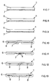
- the numeral 1 indicates a metal strip, previously bent into a semicircular shape as shown in Fig. 2 by an appropriate tool (not illustrated) and then inserted between jaws 2 and 3 of a hot crimping machine.
- Wires 4 are inserted into the hollow defined by the bent strip 1 and the strip 1 is then laterally compressed as shown in Figures 2 to 6 which illustrate different stages in the compression operation.
- the strip 1 then assumes the shape illustrated in Figures 1 and 6.
- the numeral 5 indicates the crimp contact formed by the strip 1 after being shaped and compressed.
- the strip 1 is made of an electrically conductive base material 6 (for example copper) backed with a soldering material (for example tin or silver).
- a soldering material for example tin or silver
- This method in addition to crimping the contact, also forms a soldered joint.
- Figures 7 to 13 are cross sections of different forms which the strip 1 may have before being finished, that is, before it is bent over and compressed to form the crimp contact 5.
- the layer of soldering material 7 has a corrugated surface to improve the grip of the strip 1 on the wires 4.
- the layer 7 is a flat lamina placed inside the hollow formed by the layer 6 which is bent into a flattened C shape.
- Fig. 11 is similar to the strip illustrated in Fig. 10 but the layer of soldering material 7 is bowed.
- soldering material 7 is a wire or circular bar.
- the layer 7 has a quadrangular, trapezoidal section.
- the numeral 8 indicates solder flux in powder or paste form placed between the base conductor 6 and the soldering material 7 (see Figs. 10, 11, 12 and 13).
- the function of the flux is to improve the soldering by eliminating the so-called "cool spots".
- the strip 1 may have longitudinal ribbing (not illustrated) designed to increase the mechanical strength of the contact 5 and to stop it from accidentally opening.
- the crimp contact disclosed by the present invention may therefore be used to make perfect electrical connection between wires that are simply enamelled.
- the crimp contact 5 made in this way can be quickly and easily fitted to the contact base (of the power supply, for example) which thus becomes a type of female connector.
- the contact 5 disclosed also advantageously assumes the function of a connecting pin.
Landscapes
- Connections Effected By Soldering, Adhesion, Or Permanent Deformation (AREA)
- Installation Of Indoor Wiring (AREA)
- Clamps And Clips (AREA)
Applications Claiming Priority (2)
| Application Number | Priority Date | Filing Date | Title |
|---|---|---|---|
| ITVR940013 | 1994-02-22 | ||
| IT94VR000013U IT233591Y1 (it) | 1994-02-22 | 1994-02-22 | Graffa di collegamento per fili elettrici |
Publications (2)
| Publication Number | Publication Date |
|---|---|
| EP0668628A2 true EP0668628A2 (de) | 1995-08-23 |
| EP0668628A3 EP0668628A3 (de) | 1997-06-04 |
Family
ID=11427784
Family Applications (1)
| Application Number | Title | Priority Date | Filing Date |
|---|---|---|---|
| EP95830015A Withdrawn EP0668628A3 (de) | 1994-02-22 | 1995-01-20 | Crimp kontakt zum Anschliessen elektrischer Drähte. |
Country Status (6)
| Country | Link |
|---|---|
| US (1) | US5504275A (de) |
| EP (1) | EP0668628A3 (de) |
| JP (1) | JPH07263058A (de) |
| CN (1) | CN1111830A (de) |
| CA (1) | CA2140583A1 (de) |
| IT (2) | IT233591Y1 (de) |
Cited By (2)
| Publication number | Priority date | Publication date | Assignee | Title |
|---|---|---|---|---|
| GB2349018A (en) * | 1999-04-15 | 2000-10-18 | Yazaki Corp | Joining an electrical terminal to a wire by crimping followed by fusion |
| WO2006128204A1 (de) * | 2005-06-01 | 2006-12-07 | Luvata Oy | Elektrisches verbindungselement |
Families Citing this family (7)
| Publication number | Priority date | Publication date | Assignee | Title |
|---|---|---|---|---|
| US6462297B1 (en) * | 2000-11-10 | 2002-10-08 | Motorola, Inc. | Spot-welded interconnection and method of welding electrical tabs |
| JP2002216864A (ja) * | 2001-01-19 | 2002-08-02 | Yazaki Corp | 電線の接続構造及び接続方法 |
| JP2004349026A (ja) * | 2003-05-20 | 2004-12-09 | Yazaki Corp | ホルダ及びコネクタ |
| US8436506B2 (en) * | 2010-04-13 | 2013-05-07 | GM Global Technology Operations LLC | Electric motor assemblies and systems and methods associated with joining wires of electric motor assemblies |
| US9190741B2 (en) | 2013-03-12 | 2015-11-17 | Thomas & Betts International Llc | Hybrid grounding connector |
| CN108346869B (zh) * | 2017-01-24 | 2020-07-03 | 泰科电子(上海)有限公司 | 线缆连接器 |
| DE102017123286B4 (de) * | 2017-10-06 | 2019-08-14 | Tdk Electronics Ag | Crimpverbindungsvorrichtung, gecrimpte Anordnung und Verfahren zur Herstellung einer gecrimpten Anordnung |
Family Cites Families (16)
| Publication number | Priority date | Publication date | Assignee | Title |
|---|---|---|---|---|
| US2250156A (en) * | 1939-06-02 | 1941-07-22 | Bell Telephone Labor Inc | Electrical connection |
| US2449496A (en) * | 1943-03-31 | 1948-09-14 | Frank J Matan | Electrical connection |
| US3020333A (en) * | 1953-09-29 | 1962-02-06 | Gen Electric | Means for strengthening an integrally formed joint |
| US3034195A (en) * | 1959-02-20 | 1962-05-15 | Leclabart Jean | Strand package |
| US3226471A (en) * | 1962-08-10 | 1965-12-28 | Stephen N Buchanan | Insulated splicer cap |
| US3517804A (en) * | 1967-06-07 | 1970-06-30 | Plessey Co Ltd | Jointing clips for insulated electric wires and method of making same |
| US3523173A (en) * | 1967-08-17 | 1970-08-04 | Sprague Electric Co | Insulated lead connection |
| US3443256A (en) * | 1968-03-18 | 1969-05-06 | Advance Transformer Co | Electromagnetic device with terminal connections and the method of making the connections |
| US3541227A (en) * | 1968-11-13 | 1970-11-17 | Amp Inc | Terminal for interconnecting foil conductor and wire conductor |
| US3835241A (en) * | 1972-06-30 | 1974-09-10 | Gen Cable Corp | Adaptor for modifying connector to accommodate smaller conductors |
| US4067105A (en) * | 1974-12-30 | 1978-01-10 | General Staple Co., Inc. | Method of making an insulated splice and an insulated terminal and composite supply strip therefor |
| US4087889A (en) * | 1975-07-18 | 1978-05-09 | Kabushiki Kaisha Saneisha Seisakusho | Wire connecting sleeve |
| DE3047684C2 (de) * | 1980-12-18 | 1984-02-23 | Kabelwerke Reinshagen Gmbh, 5600 Wuppertal | Elektrischer Steckverbinder, Verfahren zu seinem Anschluß und Vorrichtung zur Durchführung des Verfahrens |
| DE3921990A1 (de) * | 1988-07-08 | 1990-01-11 | Yazaki Corp | Quetschanschlussverbinder fuer leiter und verfahren zur herstellung eines quetschverbinderanschlusses |
| US5063659A (en) * | 1990-09-27 | 1991-11-12 | Gte Products Corporation | Method of joining a soldered connector to a shielded coaxial cable |
| IT224350Z2 (it) * | 1991-05-21 | 1996-03-14 | Scramoncin Ernesto | Graffa di collegamento per fili elettrici |
-
1994
- 1994-02-22 IT IT94VR000013U patent/IT233591Y1/it active IP Right Grant
- 1994-02-22 IT IT94VR000013A patent/ITVR940013A1/it unknown
-
1995
- 1995-01-19 CA CA002140583A patent/CA2140583A1/en not_active Abandoned
- 1995-01-20 EP EP95830015A patent/EP0668628A3/de not_active Withdrawn
- 1995-02-01 US US08/382,199 patent/US5504275A/en not_active Expired - Lifetime
- 1995-02-15 CN CN95101974A patent/CN1111830A/zh active Pending
- 1995-02-21 JP JP7032332A patent/JPH07263058A/ja active Pending
Cited By (4)
| Publication number | Priority date | Publication date | Assignee | Title |
|---|---|---|---|---|
| GB2349018A (en) * | 1999-04-15 | 2000-10-18 | Yazaki Corp | Joining an electrical terminal to a wire by crimping followed by fusion |
| US6334798B1 (en) | 1999-04-15 | 2002-01-01 | Yazaki Corporation | Method of and structure for connecting electric wire and connecting terminal |
| GB2349018B (en) * | 1999-04-15 | 2002-04-03 | Yazaki Corp | Method of and structure for connecting electric wire and connecting terminal |
| WO2006128204A1 (de) * | 2005-06-01 | 2006-12-07 | Luvata Oy | Elektrisches verbindungselement |
Also Published As
| Publication number | Publication date |
|---|---|
| US5504275A (en) | 1996-04-02 |
| ITVR940013A1 (it) | 1995-08-22 |
| CN1111830A (zh) | 1995-11-15 |
| ITVR940013A0 (it) | 1994-02-22 |
| CA2140583A1 (en) | 1995-08-23 |
| ITVR940013U1 (it) | 1995-08-22 |
| JPH07263058A (ja) | 1995-10-13 |
| IT233591Y1 (it) | 2000-02-01 |
| EP0668628A3 (de) | 1997-06-04 |
| ITVR940013V0 (it) | 1994-02-22 |
Similar Documents
| Publication | Publication Date | Title |
|---|---|---|
| US5025554A (en) | Method of connecting a crimp-style terminal to electrical conductors of an electrical wire | |
| US5191710A (en) | Method of forming an electrode unit | |
| JP3862870B2 (ja) | 半田レスの端子金具を備えた電気部品 | |
| US4288141A (en) | Insulation displacement contact for an electrical connector | |
| US5504275A (en) | Crimp contact for connecting electrical wires | |
| KR20010110125A (ko) | 땜납 용착물이 있는 납땜 가능한 전기적 연결 요소 | |
| US2402122A (en) | Resistive device | |
| GB2208976A (en) | Electrical crimp connector | |
| US4074065A (en) | Insulated wire splice | |
| JP3550880B2 (ja) | モータ及びモータの固定子コイル端末線接続方法 | |
| JPS648437B2 (de) | ||
| EP0675568A1 (de) | Vorrichtung und Methode zur mechanischen und elektrischen Verbindung eines Anschlusses | |
| JPH0638377Y2 (ja) | 電線接続端子 | |
| US4378619A (en) | Method for attaching connectors in foil capacitors | |
| US4644625A (en) | Plier tool for making an improved electrical connection | |
| US4482782A (en) | Method of providing a soldered electrical connection and the electrical connection | |
| JPH05300688A (ja) | 導体接続方法 | |
| JPH1079282A (ja) | 圧接端子の電線圧接方法及び圧接装置 | |
| CN1268042C (zh) | 压接热保护器件的方法 | |
| KR960007857Y1 (ko) | 형광등 안정기의 접속단자(Terminal of a power transformer) | |
| EP0027087B1 (de) | Einteiliger elektrischer Kontakt und Verfahren zur Herstellung eines einteiligen elektrischen Kontaktes | |
| JPS644218Y2 (de) | ||
| JPH01241768A (ja) | 電線圧着端子 | |
| JP2966806B2 (ja) | 平角導線の接合機構とその接合方法 | |
| JPH02219438A (ja) | 回転電機のセラミックスブラシ |
Legal Events
| Date | Code | Title | Description |
|---|---|---|---|
| PUAI | Public reference made under article 153(3) epc to a published international application that has entered the european phase |
Free format text: ORIGINAL CODE: 0009012 |
|
| AK | Designated contracting states |
Kind code of ref document: A2 Designated state(s): AT BE CH DE DK ES FR GB GR IT LI NL PT SE |
|
| RAX | Requested extension states of the european patent have changed |
Free format text: SI PAYMENT 950202 |
|
| PUAL | Search report despatched |
Free format text: ORIGINAL CODE: 0009013 |
|
| AK | Designated contracting states |
Kind code of ref document: A3 Designated state(s): AT BE CH DE DK ES FR GB GR IT LI NL PT SE |
|
| AX | Request for extension of the european patent |
Free format text: SI PAYMENT 950202 |
|
| 17P | Request for examination filed |
Effective date: 19970805 |
|
| 17Q | First examination report despatched |
Effective date: 19980529 |
|
| STAA | Information on the status of an ep patent application or granted ep patent |
Free format text: STATUS: THE APPLICATION IS DEEMED TO BE WITHDRAWN |
|
| 18D | Application deemed to be withdrawn |
Effective date: 19981009 |