EP0668983B2 - Un four - Google Patents
Un four Download PDFInfo
- Publication number
- EP0668983B2 EP0668983B2 EP94900173A EP94900173A EP0668983B2 EP 0668983 B2 EP0668983 B2 EP 0668983B2 EP 94900173 A EP94900173 A EP 94900173A EP 94900173 A EP94900173 A EP 94900173A EP 0668983 B2 EP0668983 B2 EP 0668983B2
- Authority
- EP
- European Patent Office
- Prior art keywords
- jets
- recovery boiler
- levels
- lowest
- black liquor
- Prior art date
- Legal status (The legal status is an assumption and is not a legal conclusion. Google has not performed a legal analysis and makes no representation as to the accuracy of the status listed.)
- Expired - Lifetime
Links
- 239000007789 gas Substances 0.000 claims abstract description 48
- QVGXLLKOCUKJST-UHFFFAOYSA-N atomic oxygen Chemical compound [O] QVGXLLKOCUKJST-UHFFFAOYSA-N 0.000 claims abstract description 17
- 239000001301 oxygen Substances 0.000 claims abstract description 17
- 229910052760 oxygen Inorganic materials 0.000 claims abstract description 17
- 238000002156 mixing Methods 0.000 claims abstract description 10
- 238000011084 recovery Methods 0.000 claims description 20
- 238000002485 combustion reaction Methods 0.000 claims description 15
- 239000000446 fuel Substances 0.000 abstract description 11
- 239000002245 particle Substances 0.000 abstract description 7
- 238000009826 distribution Methods 0.000 abstract description 3
- 239000007787 solid Substances 0.000 abstract description 3
- 239000012530 fluid Substances 0.000 abstract description 2
- 239000003039 volatile agent Substances 0.000 abstract 1
- MWUXSHHQAYIFBG-UHFFFAOYSA-N nitrogen oxide Inorganic materials O=[N] MWUXSHHQAYIFBG-UHFFFAOYSA-N 0.000 description 7
- 239000003546 flue gas Substances 0.000 description 6
- NINIDFKCEFEMDL-UHFFFAOYSA-N Sulfur Chemical compound [S] NINIDFKCEFEMDL-UHFFFAOYSA-N 0.000 description 5
- 239000005864 Sulphur Substances 0.000 description 5
- 238000000034 method Methods 0.000 description 5
- UGFAIRIUMAVXCW-UHFFFAOYSA-N Carbon monoxide Chemical compound [O+]#[C-] UGFAIRIUMAVXCW-UHFFFAOYSA-N 0.000 description 4
- 238000004519 manufacturing process Methods 0.000 description 3
- 239000000203 mixture Substances 0.000 description 3
- 238000004537 pulping Methods 0.000 description 3
- 238000000197 pyrolysis Methods 0.000 description 3
- 238000010304 firing Methods 0.000 description 2
- 239000010881 fly ash Substances 0.000 description 2
- 239000000463 material Substances 0.000 description 2
- 238000002844 melting Methods 0.000 description 2
- 230000008018 melting Effects 0.000 description 2
- 238000006722 reduction reaction Methods 0.000 description 2
- 239000007921 spray Substances 0.000 description 2
- 239000000126 substance Substances 0.000 description 2
- UCKMPCXJQFINFW-UHFFFAOYSA-N Sulphide Chemical compound [S-2] UCKMPCXJQFINFW-UHFFFAOYSA-N 0.000 description 1
- 230000015572 biosynthetic process Effects 0.000 description 1
- 238000006243 chemical reaction Methods 0.000 description 1
- 239000003638 chemical reducing agent Substances 0.000 description 1
- 238000004140 cleaning Methods 0.000 description 1
- 238000005094 computer simulation Methods 0.000 description 1
- 238000010276 construction Methods 0.000 description 1
- 238000001816 cooling Methods 0.000 description 1
- 230000007797 corrosion Effects 0.000 description 1
- 238000005260 corrosion Methods 0.000 description 1
- 230000007423 decrease Effects 0.000 description 1
- 230000006735 deficit Effects 0.000 description 1
- 238000001035 drying Methods 0.000 description 1
- 230000000694 effects Effects 0.000 description 1
- 230000007613 environmental effect Effects 0.000 description 1
- 230000002349 favourable effect Effects 0.000 description 1
- 239000002657 fibrous material Substances 0.000 description 1
- 229910010272 inorganic material Inorganic materials 0.000 description 1
- 239000011147 inorganic material Substances 0.000 description 1
- 239000002655 kraft paper Substances 0.000 description 1
- 238000005259 measurement Methods 0.000 description 1
- 239000000155 melt Substances 0.000 description 1
- 210000003739 neck Anatomy 0.000 description 1
- 239000011368 organic material Substances 0.000 description 1
- 239000000123 paper Substances 0.000 description 1
- 238000004886 process control Methods 0.000 description 1
- 150000003839 salts Chemical class 0.000 description 1
- 159000000000 sodium salts Chemical class 0.000 description 1
- XTQHKBHJIVJGKJ-UHFFFAOYSA-N sulfur monoxide Chemical class S=O XTQHKBHJIVJGKJ-UHFFFAOYSA-N 0.000 description 1
- 239000002699 waste material Substances 0.000 description 1
Images


Classifications
-
- F—MECHANICAL ENGINEERING; LIGHTING; HEATING; WEAPONS; BLASTING
- F23—COMBUSTION APPARATUS; COMBUSTION PROCESSES
- F23L—SUPPLYING AIR OR NON-COMBUSTIBLE LIQUIDS OR GASES TO COMBUSTION APPARATUS IN GENERAL ; VALVES OR DAMPERS SPECIALLY ADAPTED FOR CONTROLLING AIR SUPPLY OR DRAUGHT IN COMBUSTION APPARATUS; INDUCING DRAUGHT IN COMBUSTION APPARATUS; TOPS FOR CHIMNEYS OR VENTILATING SHAFTS; TERMINALS FOR FLUES
- F23L9/00—Passages or apertures for delivering secondary air for completing combustion of fuel
- F23L9/02—Passages or apertures for delivering secondary air for completing combustion of fuel by discharging the air above the fire
-
- D—TEXTILES; PAPER
- D21—PAPER-MAKING; PRODUCTION OF CELLULOSE
- D21C—PRODUCTION OF CELLULOSE BY REMOVING NON-CELLULOSE SUBSTANCES FROM CELLULOSE-CONTAINING MATERIALS; REGENERATION OF PULPING LIQUORS; APPARATUS THEREFOR
- D21C11/00—Regeneration of pulp liquors or effluent waste waters
- D21C11/12—Combustion of pulp liquors
-
- F—MECHANICAL ENGINEERING; LIGHTING; HEATING; WEAPONS; BLASTING
- F23—COMBUSTION APPARATUS; COMBUSTION PROCESSES
- F23C—METHODS OR APPARATUS FOR COMBUSTION USING FLUID FUEL OR SOLID FUEL SUSPENDED IN A CARRIER GAS OR AIR
- F23C7/00—Combustion apparatus characterised by arrangements for air supply
- F23C7/02—Disposition of air supply not passing through burner
-
- F—MECHANICAL ENGINEERING; LIGHTING; HEATING; WEAPONS; BLASTING
- F23—COMBUSTION APPARATUS; COMBUSTION PROCESSES
- F23G—CREMATION FURNACES; CONSUMING WASTE PRODUCTS BY COMBUSTION
- F23G7/00—Incinerators or other apparatus for consuming industrial waste, e.g. chemicals
- F23G7/04—Incinerators or other apparatus for consuming industrial waste, e.g. chemicals of waste liquors, e.g. sulfite liquors
-
- F—MECHANICAL ENGINEERING; LIGHTING; HEATING; WEAPONS; BLASTING
- F23—COMBUSTION APPARATUS; COMBUSTION PROCESSES
- F23C—METHODS OR APPARATUS FOR COMBUSTION USING FLUID FUEL OR SOLID FUEL SUSPENDED IN A CARRIER GAS OR AIR
- F23C2201/00—Staged combustion
- F23C2201/10—Furnace staging
- F23C2201/101—Furnace staging in vertical direction, e.g. alternating lean and rich zones
Definitions
- the invention relates to a system and a device for firing fuel supplied into the furnace as solid or fluid particles of such size and quality that their trajectories are affected by gas flows in the furnace.
- the intention is, by feeding in oxygen-containing gas, which may be air, odorous gases (which will be converted environmentally compatible in the combustion process) or flue gas, to establish such a flow pattern that intensifies the combustion process.
- oxygen-containing gas which may be air, odorous gases (which will be converted environmentally compatible in the combustion process) or flue gas
- the invention relates to combustion of waste or residual products from pulp production.
- Spent liquors from pulping processes contain organic material which produces energy when burned, and additionally, inorganic chemicals, mainly sodium salts.
- the spent liquor is sprayed into the furnace of the so-called black liquor recovery boiler by means of one or more liquor sprays, which disperse the liquor into droplets of variable size.
- Oxygen-containing gas - usually air - is in somewhat more than stoichiometric amount supplied into the furnace through special wall openings, so-called air ports. These are usually arranged at three levels called primary, secondary and tertiary. Each of these levels consists of one or, sometimes, two (one lower and one higher) horizontal or almost horizontal rows, to which air or other oxygen-containing gas mixtures are fed from one or, sometimes, two approximately horizontal ducts.
- the lowest level i.e. primary, affects the so-called char bed on the furnace floor (2).
- the bed contains solid residues of the organic content of the fuel and the inorganic material which melts and flows out of the furnace.
- the primary air oxidates the char, providing heat necessary for both melting of the inorganic salts and the chemical reduction of sulphur into sulphide.
- the latter reaction is necessary to make sulphur recovery possible in a kraft pulping process.
- the area in which the drying and pyrolysis of the liquor droplets take place is provided with necessary oxygen from the secondary level.
- the ports for this air are usually located below the liquor sprayers. In boilers with split secondary level, the upper level is sometimes located above the liquor sprays.
- the tertiary ports are usually located at one level.
- Patent publication FI 85187 sets forth an application in which the secondary air inlet ports are located at two levels.
- the patent application SE 467741 sets forth that "in the future, additional air supply over the tertiary level may be realized”.
- Velocity energy of the supplied oxygen-containing gas is of importance.
- the primary and to a certain extent also the secondary flows affect the gas layer nearest the bed surface and consequently its burning. Secondary and tertiary air are given a high velocity in order to secure good mixing of oxygen with combustible gases.
- the jets often produce very complicated, stable or unstable flow patterns, providing changing combinations of both favorable and unfavorable results.
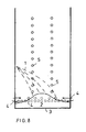
- a gas jet flowing into the furnace through a port (6) sucks and carries ambient gas (11) along with it. Consequently gas flows from all directions along the wall towards the port (jet). If there are several inlet ports near each other in a horizontal row (as in furnaces of conventional design), the jets form one resultant flat and horizontal jet. This will cause a long flat recirculation flow (10) parallelly with the wall from above and another from below. Actually, no considerable horizontal suction flows between the air inlet ports are possible, because each adjacent jet sucks in the opposite direction.
- the invention in this patent is based on the conventional construction being turned 90 degrees. A few vertical rows with a large - compared to the conventional number of levels - number of ports in each are obtained. So the flow model in the furnace is also turned 90 degrees. The long recirculation flows will work horizontally, while vertical flows - except the net flow upwards - are effectively cut by the large number of vertical jets. Instead of vertical mixing with vertically equalized temperatures and concentrations, efficient horizontal mixing is obtained. This gives considerably clearer horizontal layers where each layer is remarkably thinner than in conventional systems, and consequently stronger vertical gradients in terms of both temperatures and composition are obtained.
- jets referred to in this patent can derive from a group of adjacent inlet ports.
- the invention in this patent is not intended to cover the (two) lowest air levels which can direct affect a bed, if any, on the furnace floor.
- At least partly vertical systems are utilized instead of approximately horizontal ducts of conventional design in supplying the ports with oxygen-containing gas. Besides less complicated and thus more cost-effective designs, more simplified and efficient process control is also achieved.
- Separate vertical sections, of which each is formed of several levels arranged above each other, can therefore be controlled separately.
- Asymmetric temperature or concentration profiles in the furnace cross-section, for example, can be corrected easily by changing the pressure of oxygen-containing gas supplied to said section, without jeopardizing the vertical balance between the individual air jets.
- inlet ports are located in adjacent walls, in the front and the side wall for example, the jets cross each other. In that case the gas jet shall be located in such a manner that it passes above or below the other. If jets are directed only from opposite walls, the flow pattern can be further improved. This is obtained by letting the meeting jets by-pass each other laterally and/or vertically. If said opposite walls are a front and a rear wall, the important side geometry of the furnace can be easily controlled.
- the level of the lowest (horizontal) jet row is at a height of 1.5 m above the centre of the furnace floor.
- the distance between the levels of jets in the vertical rows is 1.5 m until about 0.5b from the furnace outlet. This means that in a 30 m high and 12 m wide furnace there are about 14 jets in each vertical row.
- the jets in the vertical rows differentiate in such a manner that the three lowest jets come from inlet ports with a larger cross-section and are supplied with air at a lower pressure than the remaining ones above.
- the jets in the vertical rows take their oxygen-containing gas from likewise vertical ducts, one duct for each row, except for the inlet ports in the middle row of the front wall. These get their gas alternately from the ducts of the left row and the right row.
- the present patent is also intended to cover the cases in which the angle between the projection of the gas jets on the horizontal plane and the wall from which they are discharged deviates from 90 degrees.
- An arrangement in which the inlet ports laterally are deviated so little that it has no considerable significance to the appearance of the flow pattern is also referred to as vertical rows.
Landscapes
- Engineering & Computer Science (AREA)
- Mechanical Engineering (AREA)
- General Engineering & Computer Science (AREA)
- Environmental & Geological Engineering (AREA)
- Chemical & Material Sciences (AREA)
- Combustion & Propulsion (AREA)
- Paper (AREA)
- Air Supply (AREA)
- Combustion Of Fluid Fuel (AREA)
- Furnace Details (AREA)
- Investigating Or Analysing Biological Materials (AREA)
- Inorganic Insulating Materials (AREA)
- Organic Low-Molecular-Weight Compounds And Preparation Thereof (AREA)
- Muffle Furnaces And Rotary Kilns (AREA)
Claims (12)
- Installation pour envoyer un gaz contenant de l'oxygène sous forme de jets, chaque jet étant formé soit par une seule embouchure d'entrée soit par un groupe d'embouchures adjacentes et les jets s'étendant à des niveaux séparés de manière à ce que tous les jets qui sont situés verticalement dans une région de +/- 0,5 m soient considérés comme des jets de même niveau dont les deux niveaux plus bas peuvent consister en rangées de jets horizontales ou légèrement inclinées, jusque dans une chaudière de récupération avec des parois approximativement plates et une section approximativement rectangulaire ou carrée, cette installation étant destinée à la combustion de liqueur noire, caractérisée en ce que aux niveaux situés au-dessus des deux plus bas, les vitesses maximales du débit de gaz vertical sont réduites et le mixage horizontal est amélioré dans la chaudière par quelques niveaux de jets approximativement horizontaux, par quoi au moins trois niveaux de jets sont situés au-dessus des deux plus bas dans l'une des parois au moins.
- Installation pour envoyer un gaz contenant de l'oxygène sous forme de jets, chaque jet étant formé soit par une seule embouchure d'entrée soit par un groupe d'embouchures adjacentes et les jets s'étendant à des niveaux séparés de manière à ce que tous les jets qui sont situés verticalement dans une région de +/- 0,5 m soient considérés comme des jets de même niveau dont les deux niveaux plus bas peuvent consister en rangées de jets horizontales ou légèrement inclinées, jusque dans une chaudière de récupération avec des parois approximativement plates et une section approximativement rectangulaire ou carrée, cette installation étant destinée à la combustion de liqueur noire, caractérisée en ce que aux niveaux situés au-dessus des deux plus bas, les vitesses maximales du débit vertical de gaz sont réduites et le mixage horizontal est amélioré dans la chaudière par un jet vertical dont la hauteur dépasse un mètre à l'origine.
- Installation selon les revendications 1 et 2, caractérisée en ce que deux des niveaux au moins situés au-dessus des deux plus bas sont disposés de telle manière qu'un jet au moins en un niveau et un jet au moins en l'autre sont alimentés avec du gaz dont la pression instantanée est commandée avec le même dispositif de commande.
- Installation selon l'une quelconque des revendications 1 à 3, caractérisée en ce que l'un des jets au moins situé au-dessus des deux niveaux les plus bas est disposé ou dirigé de telle manière à ce qu'il passe au-dessous ou au-dessus des jets rencontrés et essentiellement sans entrer en collision avec ces jets provenant des autres parois adjacentes.
- Installation selon l'une quelconque des revendications 1 à 4, caractérisée en ce que des jets (13) provenant des parois opposées (12), situés en au moins un niveau au-dessus des deux niveaux les plus bas, sont dirigés et/ou situés verticalement et/ou latéralement de telle manière qu'eux-mêmes ou leurs lignes de prolongement imaginaires (14) traversent, essentiellement sans entrer en collision avec les jets qu'ils rencontrent, le plan imaginaire (15) situé parallèlement et à mi-chemin entre lesdites parois.
- Installation selon l'une quelconque des revendications 1 à 5, caractérisée en ce qu' en des niveaux au-dessus des deux plus bas, des jets sont situés au moins en un niveau provenant principalement de la direction de deux parois opposées, appelée ici direction avant-arrière.
- Installation selon la revendication 6, caractérisée en ce qu'en des niveaux au-dessus des deux plus bas, l'agencement latéral dans la direction gauche/droite des jets est symétrique, au moins en un niveau latéral, et le nombre de jets dans la paroi avant/arrière ou dans la paroi arrière/avant est de un/deux ou deux/trois.
- Installation selon la revendication 7, caractérisée en ce qu'en des niveaux au-dessus des deux plus bas, le nombre de jets (13) par niveau et par paroi provenant des parois opposées (12) est, au moins en un niveau, de un, deux ou trois et l'agencement asymétrique de telle manière à ce que l'emplacement latéral du ou des jets sur une paroi soit approximativement symétrique avec l'image miroir des emplacements de la paroi opposée quand le plan (17) du miroir imaginaire passe par les axes centraux verticaux des parois opposées.
- Installation selon l'une quelconque des revendications 1 à 8, caractérisée en ce qu'en des niveaux au-dessus des deux plus bas, les jets dans une paroi sont situés au moins en un niveau (18) qui se situe approximativement à mi-chemin entre les niveaux (19) des jets de la paroi opposée.
- Installation selon l'une quelconque des revendications 1 à 9, caractérisée en ce qu'en des niveaux au-dessus des deux plus bas, un ou plusieurs jets situés en un niveau sont alimentés avec du gaz provenant du même conduit qu'un ou plusieurs jets situés en un ou plusieurs autres niveaux.
- Installation selon la revendication 10, caractérisée en ce qu' en des niveaux au-dessus des deux plus bas, le gaz est en un niveau envoyé à un ou plusieurs jets (20) situés dans la région comprise entre le coin (18) du fourneau et l'axe central de la paroi, axe éventuellement inclus, et provient du même conduit (21) que le ou les jets situés dans la région correspondante de ladite paroi en un ou plusieurs autres niveaux.
- Installation selon l'une quelconque des revendications 1 à 11, caractérisée en ce qu' au moins un niveau des embouchures d'entrée de gaz est situé à une hauteur minimale de 13 mètres au-dessus du point central du fond et un au moins des conduits distribuant le gaz dans les embouchures d'entrée est situé de manière à ce que l'angle entre le conduit et le plan horizontal dépasse 45°.
Applications Claiming Priority (3)
| Application Number | Priority Date | Filing Date | Title |
|---|---|---|---|
| FI925305A FI925305A0 (fi) | 1992-11-23 | 1992-11-23 | Foerfarande och anordning foer inmatning av foerbraenningsluft i en eldstad |
| FI925305 | 1992-11-23 | ||
| PCT/FI1993/000488 WO1994012829A1 (fr) | 1992-11-23 | 1993-11-18 | Systeme et dispositif d'alimentation d'un four en gaz contenant de l'oxygene |
Publications (3)
| Publication Number | Publication Date |
|---|---|
| EP0668983A1 EP0668983A1 (fr) | 1995-08-30 |
| EP0668983B1 EP0668983B1 (fr) | 1998-09-16 |
| EP0668983B2 true EP0668983B2 (fr) | 2004-09-08 |
Family
ID=8536261
Family Applications (1)
| Application Number | Title | Priority Date | Filing Date |
|---|---|---|---|
| EP94900173A Expired - Lifetime EP0668983B2 (fr) | 1992-11-23 | 1993-11-18 | Un four |
Country Status (9)
| Country | Link |
|---|---|
| US (1) | US5724895A (fr) |
| EP (1) | EP0668983B2 (fr) |
| AT (1) | ATE171259T1 (fr) |
| AU (1) | AU5467594A (fr) |
| CA (1) | CA2149755C (fr) |
| ES (1) | ES2124385T5 (fr) |
| FI (2) | FI925305A0 (fr) |
| SE (1) | SE508813C2 (fr) |
| WO (1) | WO1994012829A1 (fr) |
Cited By (1)
| Publication number | Priority date | Publication date | Assignee | Title |
|---|---|---|---|---|
| US7207280B2 (en) | 2001-04-06 | 2007-04-24 | Andritz Oy | Combustion air system for recovery boilers, burning spent liquors from pulping processes |
Families Citing this family (13)
| Publication number | Priority date | Publication date | Assignee | Title |
|---|---|---|---|---|
| US5715763A (en) * | 1995-09-11 | 1998-02-10 | The Mead Corporation | Combustion system for a black liquor recovery boiler |
| CA2220325C (fr) * | 1996-11-22 | 2003-01-14 | Mitsubishi Heavy Industries, Ltd. | Chaudiere de recuperation |
| FI102410B1 (fi) * | 1997-02-07 | 1998-11-30 | Kvaerner Pulping Oy | Menetelmä ja sovitelma ilman syöttämiseksi soodakattilaan |
| US5992337A (en) * | 1997-09-26 | 1999-11-30 | Air Liquide America Corporation | Methods of improving productivity of black liquor recovery boilers |
| FI118807B (fi) * | 2001-11-14 | 2008-03-31 | Polyrec Ab Oy | Järjestelmä soodakattilan virtauskentän hallitsemiseksi |
| US7185594B2 (en) * | 2003-07-03 | 2007-03-06 | Clyde Bergemann, Inc. | Method and apparatus for improving combustion in recovery boilers |
| FI118743B (fi) * | 2004-11-04 | 2008-02-29 | Andritz Oy | Hiillospedin ohjaus talteenottokattilassa |
| FI122982B (fi) * | 2006-06-21 | 2012-09-28 | Metso Power Oy | Menetelmä soodakattilan typpioksidipäästöjen vähentämiseksi ja soodakattila |
| US8276528B1 (en) | 2008-03-17 | 2012-10-02 | Daniel Richard Higgins | Pneumatic fuel distributor for solid fuel boilers |
| US8590463B1 (en) | 2008-05-23 | 2013-11-26 | Daniel Richard Higgins | Method and apparatus for drying solid fuels |
| US8707876B2 (en) | 2008-09-17 | 2014-04-29 | Daniel Richard Higgins | Stepped floor for solid fuel boilers |
| US8424150B1 (en) | 2009-06-11 | 2013-04-23 | Daniel Richard Higgins | Rod scraper |
| WO2015105989A1 (fr) | 2014-01-08 | 2015-07-16 | Sullivan Eugene J | Chaudière à combustion ayant une colonne de pré-séchage de combustible |
Family Cites Families (4)
| Publication number | Priority date | Publication date | Assignee | Title |
|---|---|---|---|---|
| SE149854C1 (fr) * | ||||
| JPS59205514A (ja) * | 1983-05-09 | 1984-11-21 | Toyota Kihan:Kk | 焼却炉 |
| FI85187C (fi) * | 1989-02-20 | 1992-03-10 | Tampella Oy Ab | Inmatningssystem foer braennluft i en aotervinningspanna. |
| SE9102546L (sv) * | 1991-09-05 | 1992-09-07 | Goetaverken Energy Ab | Foerbraenning av avfallsvaetskor |
-
1992
- 1992-11-23 FI FI925305A patent/FI925305A0/fi unknown
-
1993
- 1993-09-21 FI FI934123A patent/FI101420B2/fi not_active IP Right Cessation
- 1993-11-18 US US08/436,477 patent/US5724895A/en not_active Expired - Lifetime
- 1993-11-18 EP EP94900173A patent/EP0668983B2/fr not_active Expired - Lifetime
- 1993-11-18 WO PCT/FI1993/000488 patent/WO1994012829A1/fr not_active Ceased
- 1993-11-18 CA CA002149755A patent/CA2149755C/fr not_active Expired - Fee Related
- 1993-11-18 AT AT94900173T patent/ATE171259T1/de not_active IP Right Cessation
- 1993-11-18 ES ES94900173T patent/ES2124385T5/es not_active Expired - Lifetime
- 1993-11-18 AU AU54675/94A patent/AU5467594A/en not_active Abandoned
-
1995
- 1995-05-17 SE SE9501815A patent/SE508813C2/sv not_active IP Right Cessation
Non-Patent Citations (1)
| Title |
|---|
| Hjalmarsson, A.-K.: "NOx control technologies for coal combustion", in IEA Coal Research/24, June 1990, pp. 32-33 † |
Cited By (1)
| Publication number | Priority date | Publication date | Assignee | Title |
|---|---|---|---|---|
| US7207280B2 (en) | 2001-04-06 | 2007-04-24 | Andritz Oy | Combustion air system for recovery boilers, burning spent liquors from pulping processes |
Also Published As
| Publication number | Publication date |
|---|---|
| FI934123A0 (fi) | 1993-09-21 |
| FI925305A0 (fi) | 1992-11-23 |
| FI934123L (fi) | 1994-05-24 |
| CA2149755A1 (fr) | 1994-06-09 |
| SE9501815L (sv) | 1995-05-17 |
| ATE171259T1 (de) | 1998-10-15 |
| CA2149755C (fr) | 2005-06-07 |
| SE508813C2 (sv) | 1998-11-09 |
| AU5467594A (en) | 1994-06-22 |
| WO1994012829A1 (fr) | 1994-06-09 |
| US5724895A (en) | 1998-03-10 |
| SE9501815D0 (sv) | 1995-05-17 |
| EP0668983A1 (fr) | 1995-08-30 |
| EP0668983B1 (fr) | 1998-09-16 |
| ES2124385T5 (es) | 2005-03-16 |
| FI101420B (sv) | 1998-06-15 |
| FI101420B2 (fi) | 2004-09-13 |
| ES2124385T3 (es) | 1999-02-01 |
Similar Documents
| Publication | Publication Date | Title |
|---|---|---|
| EP0668983B2 (fr) | Un four | |
| US5007354A (en) | Combustion air supply system for a recovery furnace | |
| CA1308964C (fr) | Methode et appareil destines a ameliorer la circulation de fluide et le melange de gaz dans une chaudiere | |
| EP0960307B1 (fr) | Procede et dispositif de fourniture d'air a une chaudiere a lit fluidise | |
| US20090194262A1 (en) | Method for preventing corrosion on the heat exchange surfaces of a boiler, and a supply means for additional material | |
| CA2443640C (fr) | Systeme d'arrivee d'air de combustion pour chaudieres de recuperation, liqueurs residuaires de cuisson provenant de procedes kraft | |
| CA2046890C (fr) | Four de combustion en lit fluidise | |
| CS327791A3 (en) | System for the supply of combustion air and method for nox generation control | |
| CA2622163C (fr) | Systeme d'air de combustion de chaudiere de recuperation avec arrivees d'air de combustion intermediaires a alignement vertical avec niveaux multiples d'arrivees d'air tertiaires | |
| FI118807B (fi) | Järjestelmä soodakattilan virtauskentän hallitsemiseksi | |
| EP1467148B1 (fr) | Système d'air pour une chaudière à lit fluidisé | |
| CN102057220A (zh) | 在流化床锅炉中用于床料的导向漏斗、流化床锅炉及在流化床锅炉中使用的方法 | |
| WO1998035185A1 (fr) | Procede permettant d'alimenter en air une chaudiere de recuperation et dispositif a cet effet | |
| KR100231975B1 (ko) | 선화분사 구멍을 가진 질소산화물 저감형 이단노즐 | |
| CA2584050C (fr) | Systeme d'air de combustion pour chaudieres de recuperation, permettant de bruler des liqueurs residuaires provenant de procedes kraft | |
| JPS6160322B2 (fr) | ||
| KR100231974B1 (ko) | 균등분할되어 이형분사각을 갖는 질소산화물 저감형 이단노즐 |
Legal Events
| Date | Code | Title | Description |
|---|---|---|---|
| PUAI | Public reference made under article 153(3) epc to a published international application that has entered the european phase |
Free format text: ORIGINAL CODE: 0009012 |
|
| 17P | Request for examination filed |
Effective date: 19950526 |
|
| AK | Designated contracting states |
Kind code of ref document: A1 Designated state(s): AT ES FR PT |
|
| 17Q | First examination report despatched |
Effective date: 19960321 |
|
| GRAG | Despatch of communication of intention to grant |
Free format text: ORIGINAL CODE: EPIDOS AGRA |
|
| GRAG | Despatch of communication of intention to grant |
Free format text: ORIGINAL CODE: EPIDOS AGRA |
|
| GRAH | Despatch of communication of intention to grant a patent |
Free format text: ORIGINAL CODE: EPIDOS IGRA |
|
| GRAH | Despatch of communication of intention to grant a patent |
Free format text: ORIGINAL CODE: EPIDOS IGRA |
|
| GRAA | (expected) grant |
Free format text: ORIGINAL CODE: 0009210 |
|
| AK | Designated contracting states |
Kind code of ref document: B1 Designated state(s): AT ES FR PT |
|
| REF | Corresponds to: |
Ref document number: 171259 Country of ref document: AT Date of ref document: 19981015 Kind code of ref document: T |
|
| REG | Reference to a national code |
Ref country code: ES Ref legal event code: FG2A Ref document number: 2124385 Country of ref document: ES Kind code of ref document: T3 |
|
| ET | Fr: translation filed | ||
| REG | Reference to a national code |
Ref country code: PT Ref legal event code: SC4A Free format text: AVAILABILITY OF NATIONAL TRANSLATION Effective date: 19981210 |
|
| PLAV | Examination of admissibility of opposition |
Free format text: ORIGINAL CODE: EPIDOS OPEX |
|
| PLBQ | Unpublished change to opponent data |
Free format text: ORIGINAL CODE: EPIDOS OPPO |
|
| PLBI | Opposition filed |
Free format text: ORIGINAL CODE: 0009260 |
|
| 26 | Opposition filed |
Opponent name: KVAERNER PULPING OY Effective date: 19990614 |
|
| PLAV | Examination of admissibility of opposition |
Free format text: ORIGINAL CODE: EPIDOS OPEX |
|
| PLBF | Reply of patent proprietor to notice(s) of opposition |
Free format text: ORIGINAL CODE: EPIDOS OBSO |
|
| PLBF | Reply of patent proprietor to notice(s) of opposition |
Free format text: ORIGINAL CODE: EPIDOS OBSO |
|
| PLBQ | Unpublished change to opponent data |
Free format text: ORIGINAL CODE: EPIDOS OPPO |
|
| PLAB | Opposition data, opponent's data or that of the opponent's representative modified |
Free format text: ORIGINAL CODE: 0009299OPPO |
|
| R26 | Opposition filed (corrected) |
Opponent name: KVAERNER PULPING OY Effective date: 19990614 |
|
| PLAW | Interlocutory decision in opposition |
Free format text: ORIGINAL CODE: EPIDOS IDOP |
|
| RTI2 | Title (correction) |
Free format text: A FURNACE |
|
| RTI2 | Title (correction) |
Free format text: A FURNACE |
|
| APAC | Appeal dossier modified |
Free format text: ORIGINAL CODE: EPIDOS NOAPO |
|
| RTI2 | Title (correction) |
Free format text: A FURNACE |
|
| APAC | Appeal dossier modified |
Free format text: ORIGINAL CODE: EPIDOS NOAPO |
|
| APAC | Appeal dossier modified |
Free format text: ORIGINAL CODE: EPIDOS NOAPO |
|
| APAC | Appeal dossier modified |
Free format text: ORIGINAL CODE: EPIDOS NOAPO |
|
| APBU | Appeal procedure closed |
Free format text: ORIGINAL CODE: EPIDOSNNOA9O |
|
| APBU | Appeal procedure closed |
Free format text: ORIGINAL CODE: EPIDOSNNOA9O |
|
| PUAH | Patent maintained in amended form |
Free format text: ORIGINAL CODE: 0009272 |
|
| STAA | Information on the status of an ep patent application or granted ep patent |
Free format text: STATUS: PATENT MAINTAINED AS AMENDED |
|
| 27A | Patent maintained in amended form |
Effective date: 20040908 |
|
| AK | Designated contracting states |
Kind code of ref document: B2 Designated state(s): AT ES FR PT |
|
| APAA | Appeal reference recorded |
Free format text: ORIGINAL CODE: EPIDOS REFN |
|
| REG | Reference to a national code |
Ref country code: ES Ref legal event code: DC2A Date of ref document: 20041029 Kind code of ref document: T5 |
|
| ET3 | Fr: translation filed ** decision concerning opposition | ||
| APAH | Appeal reference modified |
Free format text: ORIGINAL CODE: EPIDOSCREFNO |
|
| PGFP | Annual fee paid to national office [announced via postgrant information from national office to epo] |
Ref country code: AT Payment date: 20071130 Year of fee payment: 15 |
|
| PGFP | Annual fee paid to national office [announced via postgrant information from national office to epo] |
Ref country code: PT Payment date: 20081119 Year of fee payment: 16 |
|
| PGFP | Annual fee paid to national office [announced via postgrant information from national office to epo] |
Ref country code: FR Payment date: 20081128 Year of fee payment: 16 |
|
| PG25 | Lapsed in a contracting state [announced via postgrant information from national office to epo] |
Ref country code: AT Free format text: LAPSE BECAUSE OF NON-PAYMENT OF DUE FEES Effective date: 20081118 |
|
| PGFP | Annual fee paid to national office [announced via postgrant information from national office to epo] |
Ref country code: ES Payment date: 20091120 Year of fee payment: 17 |
|
| REG | Reference to a national code |
Ref country code: PT Ref legal event code: MM4A Free format text: LAPSE DUE TO NON-PAYMENT OF FEES Effective date: 20100518 |
|
| PG25 | Lapsed in a contracting state [announced via postgrant information from national office to epo] |
Ref country code: PT Free format text: LAPSE BECAUSE OF NON-PAYMENT OF DUE FEES Effective date: 20100518 |
|
| REG | Reference to a national code |
Ref country code: FR Ref legal event code: ST Effective date: 20100730 |
|
| PG25 | Lapsed in a contracting state [announced via postgrant information from national office to epo] |
Ref country code: FR Free format text: LAPSE BECAUSE OF NON-PAYMENT OF DUE FEES Effective date: 20091130 |
|
| REG | Reference to a national code |
Ref country code: ES Ref legal event code: FD2A Effective date: 20120110 |
|
| PG25 | Lapsed in a contracting state [announced via postgrant information from national office to epo] |
Ref country code: ES Free format text: LAPSE BECAUSE OF NON-PAYMENT OF DUE FEES Effective date: 20101119 |