EP0669091B1 - ZAHNBüRSTE UND ELEKTRISCH ANGETRIEBENE ZAHNBüRSTE - Google Patents
ZAHNBüRSTE UND ELEKTRISCH ANGETRIEBENE ZAHNBüRSTE Download PDFInfo
- Publication number
- EP0669091B1 EP0669091B1 EP93923657A EP93923657A EP0669091B1 EP 0669091 B1 EP0669091 B1 EP 0669091B1 EP 93923657 A EP93923657 A EP 93923657A EP 93923657 A EP93923657 A EP 93923657A EP 0669091 B1 EP0669091 B1 EP 0669091B1
- Authority
- EP
- European Patent Office
- Prior art keywords
- tooth
- toothbrush
- bristles
- bristle
- grip handle
- Prior art date
- Legal status (The legal status is an assumption and is not a legal conclusion. Google has not performed a legal analysis and makes no representation as to the accuracy of the status listed.)
- Expired - Lifetime
Links
- 230000000712 assembly Effects 0.000 claims description 71
- 238000000429 assembly Methods 0.000 claims description 71
- 230000001154 acute effect Effects 0.000 claims description 2
- 239000012858 resilient material Substances 0.000 claims 1
- 210000003739 neck Anatomy 0.000 abstract description 49
- 208000006558 Dental Calculus Diseases 0.000 abstract description 17
- 238000007790 scraping Methods 0.000 abstract description 5
- 208000002925 dental caries Diseases 0.000 abstract description 3
- 201000010099 disease Diseases 0.000 abstract 1
- 208000037265 diseases, disorders, signs and symptoms Diseases 0.000 abstract 1
- 230000007246 mechanism Effects 0.000 description 19
- 230000001680 brushing effect Effects 0.000 description 14
- 238000000034 method Methods 0.000 description 8
- 230000008569 process Effects 0.000 description 4
- 229910001220 stainless steel Inorganic materials 0.000 description 3
- 239000010935 stainless steel Substances 0.000 description 3
- 210000000332 tooth crown Anatomy 0.000 description 3
- 239000000835 fiber Substances 0.000 description 2
- 241000904500 Oxyspora paniculata Species 0.000 description 1
- 230000008859 change Effects 0.000 description 1
- 230000008878 coupling Effects 0.000 description 1
- 238000010168 coupling process Methods 0.000 description 1
- 238000005859 coupling reaction Methods 0.000 description 1
- 238000010586 diagram Methods 0.000 description 1
- 235000013305 food Nutrition 0.000 description 1
- 230000018984 mastication Effects 0.000 description 1
- 238000010077 mastication Methods 0.000 description 1
- 235000012054 meals Nutrition 0.000 description 1
- 210000000056 organ Anatomy 0.000 description 1
- 230000003014 reinforcing effect Effects 0.000 description 1
- 230000007480 spreading Effects 0.000 description 1
- 229920003002 synthetic resin Polymers 0.000 description 1
- 239000000057 synthetic resin Substances 0.000 description 1
- XLYOFNOQVPJJNP-UHFFFAOYSA-N water Substances O XLYOFNOQVPJJNP-UHFFFAOYSA-N 0.000 description 1
Images









Classifications
-
- A—HUMAN NECESSITIES
- A61—MEDICAL OR VETERINARY SCIENCE; HYGIENE
- A61C—DENTISTRY; APPARATUS OR METHODS FOR ORAL OR DENTAL HYGIENE
- A61C17/00—Devices for cleaning, polishing, rinsing or drying teeth, teeth cavities or prostheses; Saliva removers; Dental appliances for receiving spittle
- A61C17/16—Power-driven cleaning or polishing devices
- A61C17/22—Power-driven cleaning or polishing devices with brushes, cushions, cups, or the like
- A61C17/222—Brush body details, e.g. the shape thereof or connection to handle
-
- A—HUMAN NECESSITIES
- A46—BRUSHWARE
- A46B—BRUSHES
- A46B5/00—Brush bodies; Handles integral with brushware
-
- A—HUMAN NECESSITIES
- A46—BRUSHWARE
- A46B—BRUSHES
- A46B13/00—Brushes with driven brush bodies or carriers
- A46B13/02—Brushes with driven brush bodies or carriers power-driven carriers
-
- A—HUMAN NECESSITIES
- A46—BRUSHWARE
- A46B—BRUSHES
- A46B5/00—Brush bodies; Handles integral with brushware
- A46B5/0004—Additional brush head
- A46B5/0008—Brushes with two or more heads on the same end of a handle not intended for simultaneous use
-
- A—HUMAN NECESSITIES
- A46—BRUSHWARE
- A46B—BRUSHES
- A46B5/00—Brush bodies; Handles integral with brushware
- A46B5/0004—Additional brush head
- A46B5/0012—Brushes with two or more heads on the same end of a handle for simultaneous use, e.g. cooperating with each-other
-
- A—HUMAN NECESSITIES
- A46—BRUSHWARE
- A46B—BRUSHES
- A46B7/00—Bristle carriers arranged in the brush body
- A46B7/02—Bristle carriers arranged in the brush body in an expanding or articulating manner
-
- A—HUMAN NECESSITIES
- A46—BRUSHWARE
- A46B—BRUSHES
- A46B9/00—Arrangements of the bristles in the brush body
- A46B9/02—Position or arrangement of bristles in relation to surface of the brush body, e.g. inclined, in rows, in groups
- A46B9/026—Position or arrangement of bristles in relation to surface of the brush body, e.g. inclined, in rows, in groups where the surface of the brush body or carrier is not in one plane, e.g. not flat
-
- A—HUMAN NECESSITIES
- A46—BRUSHWARE
- A46B—BRUSHES
- A46B9/00—Arrangements of the bristles in the brush body
- A46B9/02—Position or arrangement of bristles in relation to surface of the brush body, e.g. inclined, in rows, in groups
- A46B9/04—Arranged like in or for toothbrushes
-
- A—HUMAN NECESSITIES
- A46—BRUSHWARE
- A46B—BRUSHES
- A46B9/00—Arrangements of the bristles in the brush body
- A46B9/02—Position or arrangement of bristles in relation to surface of the brush body, e.g. inclined, in rows, in groups
- A46B9/04—Arranged like in or for toothbrushes
- A46B9/045—Arranged like in or for toothbrushes specially adapted for cleaning a plurality of tooth surfaces simultaneously
-
- A—HUMAN NECESSITIES
- A61—MEDICAL OR VETERINARY SCIENCE; HYGIENE
- A61C—DENTISTRY; APPARATUS OR METHODS FOR ORAL OR DENTAL HYGIENE
- A61C17/00—Devices for cleaning, polishing, rinsing or drying teeth, teeth cavities or prostheses; Saliva removers; Dental appliances for receiving spittle
- A61C17/16—Power-driven cleaning or polishing devices
- A61C17/22—Power-driven cleaning or polishing devices with brushes, cushions, cups, or the like
- A61C17/24—Power-driven cleaning or polishing devices with brushes, cushions, cups, or the like rotating continuously
- A61C17/26—Power-driven cleaning or polishing devices with brushes, cushions, cups, or the like rotating continuously driven by electric motor
-
- A—HUMAN NECESSITIES
- A61—MEDICAL OR VETERINARY SCIENCE; HYGIENE
- A61C—DENTISTRY; APPARATUS OR METHODS FOR ORAL OR DENTAL HYGIENE
- A61C17/00—Devices for cleaning, polishing, rinsing or drying teeth, teeth cavities or prostheses; Saliva removers; Dental appliances for receiving spittle
- A61C17/16—Power-driven cleaning or polishing devices
- A61C17/22—Power-driven cleaning or polishing devices with brushes, cushions, cups, or the like
- A61C17/32—Power-driven cleaning or polishing devices with brushes, cushions, cups, or the like reciprocating or oscillating
- A61C17/34—Power-driven cleaning or polishing devices with brushes, cushions, cups, or the like reciprocating or oscillating driven by electric motor
-
- A—HUMAN NECESSITIES
- A61—MEDICAL OR VETERINARY SCIENCE; HYGIENE
- A61C—DENTISTRY; APPARATUS OR METHODS FOR ORAL OR DENTAL HYGIENE
- A61C17/00—Devices for cleaning, polishing, rinsing or drying teeth, teeth cavities or prostheses; Saliva removers; Dental appliances for receiving spittle
- A61C17/16—Power-driven cleaning or polishing devices
- A61C17/22—Power-driven cleaning or polishing devices with brushes, cushions, cups, or the like
- A61C17/32—Power-driven cleaning or polishing devices with brushes, cushions, cups, or the like reciprocating or oscillating
- A61C17/34—Power-driven cleaning or polishing devices with brushes, cushions, cups, or the like reciprocating or oscillating driven by electric motor
- A61C17/3409—Power-driven cleaning or polishing devices with brushes, cushions, cups, or the like reciprocating or oscillating driven by electric motor characterized by the movement of the brush body
- A61C17/3445—Translation along the axis of the toothbrush handle
-
- A—HUMAN NECESSITIES
- A61—MEDICAL OR VETERINARY SCIENCE; HYGIENE
- A61C—DENTISTRY; APPARATUS OR METHODS FOR ORAL OR DENTAL HYGIENE
- A61C17/00—Devices for cleaning, polishing, rinsing or drying teeth, teeth cavities or prostheses; Saliva removers; Dental appliances for receiving spittle
- A61C17/16—Power-driven cleaning or polishing devices
- A61C17/22—Power-driven cleaning or polishing devices with brushes, cushions, cups, or the like
- A61C17/32—Power-driven cleaning or polishing devices with brushes, cushions, cups, or the like reciprocating or oscillating
- A61C17/34—Power-driven cleaning or polishing devices with brushes, cushions, cups, or the like reciprocating or oscillating driven by electric motor
- A61C17/349—Power-driven cleaning or polishing devices with brushes, cushions, cups, or the like reciprocating or oscillating driven by electric motor with multiple brush bodies
-
- B—PERFORMING OPERATIONS; TRANSPORTING
- B29—WORKING OF PLASTICS; WORKING OF SUBSTANCES IN A PLASTIC STATE IN GENERAL
- B29C—SHAPING OR JOINING OF PLASTICS; SHAPING OF MATERIAL IN A PLASTIC STATE, NOT OTHERWISE PROVIDED FOR; AFTER-TREATMENT OF THE SHAPED PRODUCTS, e.g. REPAIRING
- B29C45/00—Injection moulding, i.e. forcing the required volume of moulding material through a nozzle into a closed mould; Apparatus therefor
- B29C45/0001—Injection moulding, i.e. forcing the required volume of moulding material through a nozzle into a closed mould; Apparatus therefor characterised by the choice of material
-
- A—HUMAN NECESSITIES
- A46—BRUSHWARE
- A46B—BRUSHES
- A46B2200/00—Brushes characterized by their functions, uses or applications
- A46B2200/10—For human or animal care
- A46B2200/1066—Toothbrush for cleaning the teeth or dentures
-
- A—HUMAN NECESSITIES
- A61—MEDICAL OR VETERINARY SCIENCE; HYGIENE
- A61C—DENTISTRY; APPARATUS OR METHODS FOR ORAL OR DENTAL HYGIENE
- A61C17/00—Devices for cleaning, polishing, rinsing or drying teeth, teeth cavities or prostheses; Saliva removers; Dental appliances for receiving spittle
- A61C17/16—Power-driven cleaning or polishing devices
- A61C17/22—Power-driven cleaning or polishing devices with brushes, cushions, cups, or the like
- A61C17/32—Power-driven cleaning or polishing devices with brushes, cushions, cups, or the like reciprocating or oscillating
- A61C17/34—Power-driven cleaning or polishing devices with brushes, cushions, cups, or the like reciprocating or oscillating driven by electric motor
- A61C17/3409—Power-driven cleaning or polishing devices with brushes, cushions, cups, or the like reciprocating or oscillating driven by electric motor characterized by the movement of the brush body
- A61C17/3418—Rotation around the axis of the toothbrush handle
-
- A—HUMAN NECESSITIES
- A61—MEDICAL OR VETERINARY SCIENCE; HYGIENE
- A61C—DENTISTRY; APPARATUS OR METHODS FOR ORAL OR DENTAL HYGIENE
- A61C2204/00—Features not otherwise provided for
- A61C2204/002—Features not otherwise provided for using batteries
-
- B—PERFORMING OPERATIONS; TRANSPORTING
- B29—WORKING OF PLASTICS; WORKING OF SUBSTANCES IN A PLASTIC STATE IN GENERAL
- B29C—SHAPING OR JOINING OF PLASTICS; SHAPING OF MATERIAL IN A PLASTIC STATE, NOT OTHERWISE PROVIDED FOR; AFTER-TREATMENT OF THE SHAPED PRODUCTS, e.g. REPAIRING
- B29C45/00—Injection moulding, i.e. forcing the required volume of moulding material through a nozzle into a closed mould; Apparatus therefor
- B29C45/0025—Preventing defects on the moulded article, e.g. weld lines, shrinkage marks
-
- B—PERFORMING OPERATIONS; TRANSPORTING
- B29—WORKING OF PLASTICS; WORKING OF SUBSTANCES IN A PLASTIC STATE IN GENERAL
- B29K—INDEXING SCHEME ASSOCIATED WITH SUBCLASSES B29B, B29C OR B29D, RELATING TO MOULDING MATERIALS OR TO MATERIALS FOR MOULDS, REINFORCEMENTS, FILLERS OR PREFORMED PARTS, e.g. INSERTS
- B29K2059/00—Use of polyacetals, e.g. POM, i.e. polyoxymethylene or derivatives thereof, as moulding material
Definitions
- the present invention relates to a toothbrush and an electric toothbrush for efficiently removing plaque, tartar, and calculus from teeth.
- Teeth are an important organ indispensable for the mastication of food and the utterance of speech sounds. In order for the teeth to perform their functions, it is necessary for them to be brushed after meals or before sleeping to prevent tartar and calculus from being deposited on dental necks for protection against periodontites.
- Toothbrushes and electric toothbrushes which are respectively manually and automatically operable, are generally used by turning the bristle assemblies back and forth about the toothbrush axis.
- the bristle assemblies When the handle of a toothbrush is rocked about its own axis in use, the bristle assemblies are angularly moved alternately upwardly and downwardly. More specifically, when the user of an electric toothbrush holds its grip cylinder and angularly moves the bristle assemblies about the axis while keeping the bristle assemblies against a tooth side or neck, a downward swinging movement of the bristle assemblies peels an end of the gum off the tooth neck, and pushes a deposit of plaque into a recess that is formed between the peeled gum and the tooth neck. Therefore, the brushing operation tends to produce a deposit of tartar and calculus, causing periodontites such as dentoalveolitis.
- JP-U-54/83976, JP-U-61/86038, JP-U-59/73913 and JP-A-55/108310 (over which claim 1 has been characterised) to provide a toothbrush having bristles which are arranged to clean simultaneously more than one surface of the tooth during brushing, for example, the sides and the occlusal area of the tooth.
- CH-A-175862 It is also known from CH-A-175862 to provide a two headed toothbrush, the heads of which are held apart at a large obtuse angle by a coil spring.
- the bristles are arranged such that, in use, those bristles brushing the sides of the tooth are angled in a direction which extends away from the tip end and occlusal area of the tooth and toward the gum and root of the tooth.
- a toothbrush comprising:
- Such a toothbrush is advantageous because the frictional force exerted by the bristle tips is strong upon movement toward the tip of the crown and occlusal area of the tooth and weaker upon movement in the opposite direction. In this way, plaque, tartar and calculus deposited on the tooth side and tooth neck are brushed away from the region of the gum. The gum is also not peeled back away from the tooth neck during brushing with such a toothbrush, and so can be maintained in a healthy condition.
- a toothbrush comprises:
- an electric toothbrush comprises:
- the crown cap has adjusting means for adjusting the projection of one of the bristle assemblies, and mounting means for mounting a distal end of the grip handle or the handle detachably on a longitudinal end of the crown cap.
- the electric actuator means is not limited to any structure, but may comprise a known means such as a combination of a motor and a cam mechanism.
- the mounting means for detachably mounting the grip handle or the handle on the crown cap is not limited any particular structure.
- the mounting means may be composed of known means, e.g., engaging holes defined in the opposite ends of the crown cap and an engaging body mounted on the distal end of the grip handle or the handle and engaging in one of the engaging holes, or alternatively, an engaging hole defined longitudinally through the crown cap and an engaging shaft mounted on the distal end of the grip handle or the handle and engaging in the engaging hole.
- the bristle assemblies are inclined at an angle of 45°, for example, to the inner surfaces of the crown cap.
- the angle of inclination is not limited to 45°.
- the bristle assemblies are not limited to any particular length, but may have the same length or lengths that vary stepwise.
- the adjusting means for adjusting the projection of one of the bristle assemblies is not limited to any particular structure, but may be known means, e.g., a screw for moving a base on which the bristle assembly is planted into and out of the crown cap.
- a toothbrush comprises:
- an electric toothbrush comprises:
- the crown cap has only a molar tooth fitting portion and a bristle assembly corresponding thereto.
- the crown cap has only a front tooth fitting portion and a bristle assembly corresponding thereto.
- the bristle assemblies should preferably be inclined at an angle of 45° to the surfaces of a molar or front teeth that is fitted in the tooth fitting portion.
- the angle of inclination is not limited to 45°, but may be selected in a range from 30° to 60°.
- a toothbrush comprises:
- a toothbrush comprises:
- the toothbrush bodies should preferably be attached such that the bristle assemblies are inclined at an angle of 45° with respect to sides of teeth that are inserted.
- the angle of inclination is not limited to 45°, but may be selected in a range from 30° to 60°.
- the number of toothbrush bodies may generally range from two to three though not limited to any particular value. If two toothbrush bodies are employed, then they are positioned respectively on the corresponding opposite sides of teeth, or one of them is positioned on the occlusal tooth area of the teeth and the other on one of the sides of the teeth. If three toothbrush bodies are employed, then one of them is positioned on the occlusal tooth area of the teeth and the others on the respective sides of the teeth.
- the angle of inclination of the bristle assemblies were less than 30° or greater than 60°, then they would not sufficiently scrape off plaque or the like because the pressure applied by the tip ends of the bristle assemblies to the tooth surfaces would be weak.
- an electric toothbrush comprises a bristle assembly reciprocally angularly movable to swing upwardly along teeth sides while being held against the teeth sides or neighboring regions, reciprocally rocking means for angularly moving the bristle assembly and an actuator coupled to the reciprocally rocking means.
- the bristle assembly may be mounted in one side of a casing having a substantially inverted L shape, and a temporary positioning member may be mounted on the other side of the casing for temporarily positioning the bristle assembly for engagement with a tooth side.
- the temporary positioning member may comprise a resilient member.
- the temporary positioning member may comprise bristles.
- the temporary positioning member may be adjustable in height.
- the bristle assembly may comprise an upper set of bristles and a lower set of bristles, the lower set of bristles being longer than the upper set of bristles.
- the bristle assembly comprises an upper set of bristles, a middle set of bristles, and a lower set of bristles, the bristles being of longer, shorter, and medium lengths successively from the lower set through the middle set to the upper set.
- the toothbrush when the toothbrush is used, one of the bristle assemblies is held against the occlusal tooth areas of teeth and the other against the boundaries (tooth necks) between the tooth sides and the gum. If the toothbrush is a manual toothbrush, then the grip handle is manually angularly moved reciprocally about the axis thereof. If the toothbrush is an electric toothbrush, the grip handle is angularly moved reciprocally about the axis thereof by the electric actuator means.
- the toothbrush has the adjusting means for adjusting the projection of one of the bristle assemblies, then the projection of the bristle assembly is adjusted by the adjusting means such that the bristle assembly adjustable by the adjusting means will abut against the occlusal tooth areas of teeth and the other bristle assemblies will abut reliably against the boundaries (the tooth necks) between the tooth sides and the gum.
- the toothbrush with the adjusting means has a particular orientation in order to keep the adjustable bristle assembly in abutment against the occlusal tooth areas of teeth at all times.
- the crown cap can be attached in a different position to change the orientation of the toothbrush for brushing all the surfaces of teeth. Specific details will be described later with respect to embodiments given below.
- a molar tooth is fitted in the molar tooth fitting portion or a front tooth is fitted in the front tooth fitting portion.
- Each of the bristle assemblies is held in contact with the surface of the tooth at an angle ranging from 30° to 60°. If the toothbrush is a manual toothbrush, then the grip handle is manually angularly moved reciprocally about the axis thereof, or in the direction of the tooth axis, or in the direction normal thereto. If the toothbrush is an electric toothbrush, the grip handle is angularly moved reciprocally about the axis thereof, or in the direction of the tooth axis, or in the direction normal thereto, by the electric actuator means.
- a tooth when the toothbrush is used, a tooth is fitted in the space surrounded by the bristle assemblies.
- the bristle assemblies positioned on tooth sides are held in contact with the tooth sides at an angle ranging from 30° to 60°.
- the grip handle is manually vibrated about the axis thereof, or in the direction of the tooth axis, or in the direction normal thereto.
- the grip handle is vibrated about the axis thereof, or in the direction of the tooth axis, or in the direction normal thereto, by the electric actuator means.
- the bristle assembly when the electric toothbrush is used to brush a tooth, the bristle assembly is brought into abutment against a side or neck of the tooth while being held substantially horizontally, and angularly moved reciprocally so as to swing upwardly by the reciprocally rocking means coupled to the actuator.
- the bristle assembly may be mounted in one side of the casing of a substantially inverted L shape, and the temporary positioning member may be mounted on the other side of the casing for temporarily positioning the bristle assembly for engagement with the tooth side.
- the temporary positioning member can be held against the occlusal tooth area of the tooth crown for thereby accurately holding the bristle assembly against the tooth side or the tooth neck for scraping off deposited plaque.
- the temporary positioning member may comprise a resilient member or bristles, and may be adjustable in height. This arrangement allows the temporary positioning member to hold the bristle assembly accurately against a tooth surface ranging from the tooth side to the tooth neck without slipping over the occlusal tooth area of the tooth crown.
- the bristle assembly may comprise an upper set of bristles and a lower set of bristles, the lower set of bristles being longer than the upper set of bristles.
- the bristle assembly may comprise an upper set of bristles, a middle set of bristles, and a lower set of bristles, the bristles being of longer, shorter, and medium lengths successively from the lower set through the middle set to the upper set.
- the bristle assemblies since they are angularly movable reciprocally, are planted so as to be inclined to the tooth surface, the frictional force is stronger upon angular movement toward the tip end of the tooth, and weaker upon angular movement in the opposite direction. Therefore, plaque, tartar, and calculus deposited on the occlusal tooth area, the tooth side, and the tooth neck are gathered toward the center of the tooth fitting portion. For the same reason, the gum is not peeled off the tooth neck, and plaque, tartar, and calculus deposited, on the tooth neck are removed without being pushed between the tooth and the gum.
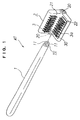
- a toothbrush A1 which is manually operable in use comprises a grip handle 1, a crown cap 2, and bristle assemblies 3, 3a.
- the grip handle 1 is in the form of a rod of plastic and has an engaging body 10 as a mounting means on its distal end.
- the engaging body 10 comprises a pair of juxtaposed flexible members 11 spaced from each other and each composed of an engaging member having a curved outer side projecting outwardly.
- the crown cap 2 comprises a member made of plastic and having a predetermined length, and has a substantially L-shaped cross section.
- the crown cap 2 has a vertical wing 21 for covering a tooth side and a horizontal wing 22 for covering an occlusal tooth area.
- the crown cap 2 has a pair of engaging holes 20 (one shown in FIG. 2) defined in the respective corners of longitudinal ends thereof, each of the engaging holes 20 serving as part of the mounting means for receiving the engaging body 10.
- the engaging body 10 can easily engage in and disengage from one of the engaging holes 20 with small forces, and can be fixed in position when engaging in one of the engaging holes 20.
- the bristle assemblies 3, 3a are mounted on respective inner surfaces of the vertical and horizontal wings 21, 22 of the crown cap 2.
- the bristle assemblies 3 on the vertical wing 21 are directly planted on the inner surface thereof such that their distal ends are inclined at an angle of substantially 45° toward the bent corner of the crown cap 2.
- the bristle assembly 3a on the horizontal wing 22 is mounted on its inner surface such that the projection of the bristle assembly 3a from the inner surface of the horizontal wing 22 can be adjusted in a certain range by an adjusting means.
- the adjusting means comprises a bristle base 30 in the form of an elongate rectangular plate.
- the bristle base 30 is disposed in a rectangular guide hole 24 defined in the horizontal wing 22 for sliding movement into and out of the guide hole 24.
- An adjustment screw 25 threaded through a ceiling of the guide hole 24 has a tip end rotatably mounted in a central area of an inner wall of the bristle base 30. When the adjustment screw 25 is turned, the bristle base 30 slides into or out of the guide hole 24, thereby adjusting the projection of the bristle assembly 3a in a certain range.
- the bristle assembly 3a is planted on the bristle base 30 such that their distal ends are inclined at an angle of substantially 45° toward the bent corner of the crown cap 2.
- the bristle assemblies 3, 3a have bristles 41 whose tip ends are bent toward the bent corner of the crown cap 2 and are rounded.
- the bristles 41 thus shaped are sufficiently effective to remove plaque off teeth without damaging. the gum when they brush the teeth.
- the toothbrush to brush the outer surfaces of teeth on the lower jaw ranging from left back teeth to front teeth, and the inner surfaces of teeth on the lower jaw ranging from right back to front teeth, and also to brush the inner surfaces of teeth on the upper jaw ranging from left back to front teeth and the outer surfaces of teeth on the upper jaw ranging from right back to front teeth.
- the toothbrush If the crown cap 2 is mounted in the opposite direction on the grip handle 1, then it is possible for the toothbrush to brush the outer surfaces of teeth on the lower jaw ranging from right back teeth to front teeth, and the inner surfaces of teeth on the lower jaw ranging from left back to front teeth, and also to brush the inner surfaces of teeth on the upper jaw ranging from right back to front teeth and the outer surfaces of teeth on the upper jaw ranging from left back to front teeth.
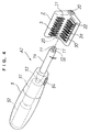
- FIG. 4 is an exploded perspective view of a preferred electric toothbrush according to the present invention.
- An electric toothbrush A2 has a grip base 5 including a handle 1a on its distal end.
- the handle 1a can be actuated by a motor 51 housed as an electric actuator means in the grip base. 5, to angularly move back and forth about its own axis through a converter mechanism 53.
- the converter mechanism 53 is of a known structure, and will not be described in detail.
- the handle 1a only moves angularly back and forth about its own axis. However, it is possible for the handle 1a to switch to back-and-forth sliding movement in the axial direction.
- a battery 52 is also housed in the grip base 5 and a switch 54 is mounted on the grip base 5.
- a method of using the electric toothbrush A2 and operation thereof are substantially the same as those of the toothbrush A1 except that the bristle assemblies 3, 3a are angularly moved back and forth by electric energy for higher efficiency.
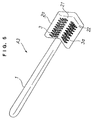
- FIG. 5 is a perspective view of a toothbrush according to another embodiment of the present invention.
- a toothbrush A3 which is manually operable in use in the same manner as with the toothbrush A1.
- the toothbrush A3 is structurally different from the toothbrush A1 in that a grip handle 1 is fixed to an end of a crown cap 2a, and a bristle assembly 3a is directly planted on a horizontal wing 22 without the brush base 30, etc. used as adjusting means.
- toothbrush A3 The structure of other portions of the toothbrush A3 is the same as that of the toothbrush A1, and will not be described in detail. Those parts of the toothbrush A3 which are identical or equivalent to those of the toothbrush A1 are denoted by identical reference numerals.
- a process of using the toothbrush A3 and operation thereof are substantially the same as those of the toothbrush A1.
- the toothbrush A3 has no adjusting means for bristle assemblies unlike the toothbrush A1, and the projection of the bristle assemblies cannot be adjusted. Since the wings of the crown cap 2a are structurally identical to each other, the toothbrush A3 has no particular orientation, and can be used more conveniently as the crown cap 2a does not need to be changed in direction.
- a toothbrush A4 which is manually operable in use comprises a grip handle 1 and a crown cap 2.
- the grip handle 1 is in the form of a rod of plastic and the crown cap 2 is fixed to a distal end of the grip handle 1.
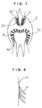
- the crown cap 2 is molded of plastic and has a molar tooth fitting portion 90 having a substantially heart-shaped cross section and a front tooth fitting portion 91 having a substantially V-shaped cross section.
- the front tooth fitting portion 91 is of a curved shape such that its central region is slightly narrow as viewed in plan.
- the crown cap 2 has a round outer profile for protecting the inside of a mouth when in use.
- a bristle assembly 3' is planted on the inner surface of the molar tooth fitting portion 90 substantially in its entirety such that the bristle assembly 3' is inclined at an angle of substantially 45° to surfaces of molar teeth to be fitted in the molar tooth fitting portion 90.
- a bristle assembly 3a' is planted on the inner surface of the front tooth fitting portion 91 substantially in its entirety such that the bristle assembly 3a' is inclined at an angle of substantially 45° to surfaces of front teeth to be fitted in the front tooth fitting portion 91.
- the bristle assemblies 3', 3a' have bristles 41 whose tip ends are bent toward the bent corner of the crown cap 2 and are rounded.
- the bristles 41 thus shaped are sufficiently effective to remove plaque off teeth without damaging the gum when they brush the teeth.
- FIG. 9 is a perspective view of an electric toothbrush according to a preferred embodiment of the present invention.
- An electric toothbrush A5 has a grip base 5 including a handle 1a on its distal end.
- the handle 1a can be actuated by a motor 51 housed as an electric actuator means in the grip base 5, to angularly move back and forth about its own axis (as indicated by the arrows "a") and in the direction of the tooth axis (as indicated by arrows "b") through a converter mechanism 53.
- the converter mechanism 53 is of a known structure, and will not be described in detail.
- the handle 1a it is possible for the handle 1a to switch in its movement between the direction around its own axis, the direction of the tooth axis, and the direction normal thereto with a selector switch (not shown).
- a battery 52 is also housed in the grip base 5 and a switch 54 is mounted on the grip base 5.
- a method of using the electric toothbrush A5 and operation thereof are substantially the same as those of the toothbrush A4 except that the bristle assemblies 3', 3a' are angularly moved back and forth by electric energy for higher efficiency.
- FIGS. 10 and 11 are front elevational views showing other structures of crown caps.
- a crown cap 2a shown in FIG. 10 is of a structure having a molar tooth fitting portion 90 and bristle assembly 3' only, and is used solely for brushing molar teeth.
- a crown cap 2b shown in FIG. 11 is of a structure having a front tooth fitting portion 91 and bristle assembly 3a' only, and is used solely for brushing front teeth.
- crown caps 2a, 2b operate substantially in the same manner as the crown cap 2 according to the above embodiment, the crown caps 2a, 2b are simpler in structure and smaller in size, and hence can be moved easily in the mouth.
- a toothbrush A6 which is manually operable in use comprises a grip handle 1 and three toothbrush bodies 92a, 92b, 92c.
- the grip handle 1 is in the form of a rod of plastic and the toothbrush bodies 92a, 92b, 92c are detachably mounted on a distal end of the grip handle 1.
- Each of the toothbrush bodies 92a, 92b, 92c has a handle 93 with bristle assemblies 94 mounted on its distal end portion which have a round profile for protecting the inside the mouth from damage during use.
- the structure by which the toothbrush bodies 92a, 92b, 92c are attached to the grip handle 1 will be described below.
- the distal end-of the grip handle 1 has three fixing holes 95a, 95b, 95c defined therein and three threaded holes also defined therein between the fixing holes 95a, 95b, 95c and an outer surface of the grip handle 1.
- Fastening screws 12 are threaded in the respective threaded holes. When the fastening screws 12 are tightened, the respective ends of the handles 93 of the toothbrush bodies 92a, 92b, 92c that are received in the fixing holes 95a, 95b, 95C are secured therein.
- the fixing holes 95a, 95b, 95c have a substantially elliptical cross section similar to that of the handles 93, so that when the handles are inserted into the respective fixing holes 95a, 95b, 95c, the angles of the toothbrush bodies 92a, 92b, 92c about their own axes are automatically set.
- the toothbrush body 92a corresponds to the occlusal tooth area of a tooth, and its bristle assemblies 94 abut against the occlusal tooth area substantially perpendicularly thereto.
- the toothbrush bodies 92b, 92c correspond respectively to the opposite sides of the tooth.
- the bristle assemblies 94 of the toothbrush bodies 92b, 92c are inclined at an angle of substantially 45° to the tooth sides toward the tip end of the tooth which is to be fitted in a region surrounded by these bristle assemblies 94.
- the bristle assemblies 94 have bristle fibers 210 whose tip ends are bent toward the tip end of a tooth and are rounded.
- the bristle fibers 210 thus shaped are sufficiently effective to remove plaque off teeth without damaging the gum when they brush the teeth.
- a tooth T is fitted into the space surrounded by the bristle assemblies 94, and the bristle assemblies 94 corresponding to the sides of the tooth are directed substantially at 45° with respect to the tooth sides. Then, the grip handle 1 is manually vibrated around its own axis or in the direction of the tooth axis or the direction normal thereto for thereby brushing the tooth.
- the bristle assemblies 94 are vibrated at this time, since the bristle assemblies 94 are inclined to the tooth sides, the frictional force is stronger upon movement toward the tip end of the tooth, and weaker upon movement toward the roots of the tooth. Therefore, plaque, tartar, and calculus deposited on the occlusal tooth area, the tooth sides, and the tooth neck of the tooth are gathered toward the center of the tip end of the tooth. For the same reason, even when rubbed by the bristle assemblies 94, the gum is not peeled off the tooth neck, and plaque, tartar, and calculus deposited on the tooth neck are removed without being pushed between the tooth and the gum.
- FIG. 15 is a perspective view of an electric toothbrush according to a preferred embodiment of the present invention.
- An electric toothbrush A7 has a grip base 5 including an attachment 96 on its distal end. To the attachment 96, there are attached three toothbrush bodies 92a, 92b, 92c as with the toothbrush A6.
- the attachment 96 can be actuated by a motor 51 housed as an electric actuator means in the grip base 5, to angularly move back and forth about its own axis (as indicated by the arrows "a") and in the direction of the tooth axis (as indicated by arrows "b") through a converter mechanism 53.
- the converter mechanism 53 is of a known structure, and will not be described in detail.
- the attachment 96 (handles 93) to switch in its movement between the direction around its own axis and the direction of the tooth axis with a selector switch 54.
- the attachment 96 may be vibrated in the direction normal to the direction of the tooth axis (i.e., vibrated in the direction in which the attachment 96 moves into and out of the mouth).
- a battery 52 is housed in the grip base 5.
- a method of using the electric toothbrush A7 and operation thereof are substantially the same as those of the toothbrush A6 except that the toothbrush bodies 92a, 92b, 92c (the bristle assemblies 94) are vibrated by electric energy for higher efficiency.
- FIG. 16 is an exploded perspective view of an electric toothbrush according to another embodiment of the present invention.
- An electric toothbrush A8 has three handles 56a, 56b, 56c mounted on an attachment 96a.
- the handles 56a, 56b, 56c can be vibrated about their own axes independently by a converter mechanism 53.
- the handles 56a, 56b, 56c have respective fitting portions 57 of square-shaped cross section on their distal ends.
- Toothbrush bodies 92a1, 92b1, 92c1 are detachably mounted on the respective fitting portions 57.
- the toothbrush bodies 92a1, 92b1, 92c1 include respective handles 93 which have in their proximal ends respective fitting holes 201 that receive the respective fitting portions 57 fitted therein.
- the fitting portions 57 can detachably be fitted in the fitting holes 201 by known means in one operation.
- the angles at which the toothbrush bodies 92a1, 92b1, 92c1 are attached around the axis of the toothbrush are set in the same manner as with the above embodiments.
- a method of using the electric toothbrush A8 and operation thereof are essentially the same as with the electric toothbrush A7 except that the toothbrush bodies 92a1, 92b1, 92c1 can be detached and attached with ease and the toothbrush bodies 92a1, 92b1, 92c1 (the bristle assemblies 94) can be vibrated about their respective axes by electric energy.
- FIG. 17 is a fragmentary perspective view of toothbrush bodies according to a further embodiment of the present invention.
- a toothbrush body 92a2 has a handle 20, and toothbrush bodies 92b2, 92c2 which are of substantially the same extent as bristle assemblies and attached to the toothbrush body 92a2 by curved arm pins 28 of stainless steel that are disposed on opposite sides of the toothbrush body 92a2.
- the arm pins 28 are secured in position by nuts N that are tightened. When loosened, the nuts N allow only the toothbrush bodies 92b2, 92c2 to be replaced.
- the angles at which the toothbrush bodies 92a2, 92b2, 92c2 are attached around the axis of the toothbrush are set in the same manner as with the above embodiments.
- FIG. 18 is a fragmentary perspective view of toothbrush bodies according to yet a further embodiment of the present invention
- FIG. 19 is a cross-sectional view of one of the toothbrush bodies of that embodiment.
- toothbrush bodies 92b3, 92c3 are attached to a toothbrush body 92a3 by arm pins 29 extending from the neck of a handle 20 of the toothbrush body 92a3.
- an adjustment screw 25a is undetachably rotatably mounted on an upper surface of the handle 93 near its distal end.
- the adjustment screw 25a has a threaded hole 31 defined in its lower portion.
- the handle 93 has a recess 202 defined in a lower portion thereof near its distal end and housing a vertically movable body 203.
- a screw 204 is vertically fixed to an upper surface of the vertically movable body 203, and threaded in the threaded hole 31.
- a bristle assembly 94a is mounted on a lower surface of the vertically movable body 203.
- the vertically movable body 203 is vertically moved to adjust the height of the bristle assembly 94a of the toothbrush body 92a3 for use.
- the angles at which the toothbrush bodies 92a3, 92b3, 92c3 are attached around the axis of the toothbrush are set in the same manner as with the above embodiments.
- FIG. 20 is a fragmentary perspective view of toothbrush bodies according to another embodiment of the present invention.
- toothbrush bodies 92a4, 92b4, 92c4 have fitting grooves 205 defined in their respective outer surfaces, and joints 33 of stainless steel having a channel shape in front elevation are fitted in the fitting grooves 205.
- the joints 33 are secured in position to the toothbrush bodies 92a4, 92b4, 92c4, thus integrally joining the toothbrush bodies 92a4, 92b4, 92c4 to each other.
- the angles at which the toothbrush bodies 92a4, 92b4, 92c4 are attached around the axis of the toothbrush are set in the same manner as with the above embodiments.
- FIG. 21 is a fragmentary perspective view of toothbrush bodies according to yet another embodiment of the present invention.
- toothbrush bodies 92a5, 92b5, 92c5 are integrally joined to each other by a curved enclosing plate 35 of stainless steel which is fastened to them by screws 36.
- a cushion 97 made of hard sponge, rather than bristle assembly, is attached to a lower surface of the toothbrush body 92a5.
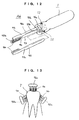
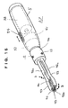
- FIGS. 22, 23, and 24 show an electric toothbrush 100 according to a further embodiment of the present invention.
- the electric toothbrush 100 has a casing 114 with a handle 112 projecting from one end thereof.
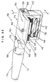
- the casing 114 houses a bristle assembly 116 reciprocally angularly movable to swing upwardly along teeth sides while being held against the teeth sides or neighboring regions, and a reciprocally rocking mechanism 118 for reciprocally angularly moving the bristle assembly 116.
- the casing 114 comprises a vertical case 120 on one side and a horizontal case 122 on another side, the cases 120, 122 being joined in an inverted L shape as viewed in end elevation.
- the horizontal case 122 is joined to the vertical case 120 so as to project from an upper end of the vertical case 120.
- the vertical case 120 and the horizontal case 122 are made of a hard synthetic resin or the like.
- the vertical case 120 has a hole 124 defined in an inner side wall thereof for placing the bristle assembly 116 therein, and a drain hole 125 defined in a bottom wall thereof for draining water out of the casing 114.
- the reciprocally rocking mechanism 118 has a rotatable shaft 126 journaled in an upper position in the vertical case 120, and a pair of swing shafts 128 disposed vertically in the vertical case 120 at respective positions near the ends of the vertical case 120.
- the rotatable shaft 126 is rotatably supported by a pair of bearings 130 disposed in the upper position in the vertical case 120.
- a pair of plate cams 132 is fixedly mounted on the rotatable shaft 126 near its opposite ends and held in sliding contact with the respective upper ends of the swing shafts 128.
- the swing shafts 128 are journaled in shaft holes that are defined in two upper bearing plates 134 horizontally disposed in the upper position in the vertical case 120, and shaft holes that are defined in a lower bearing plate 136 horizontally disposed in a lower position in the vertical case 120.
- Coil springs 138 are mounted on the swing shafts 128, respectively, between the upper bearing plates 134 for normally urging the swing shafts 128 to move upwardly.
- Pivot supports 140 by which the bristle assembly 116 are pivotally supported are fixedly mounted in upper and lower regions on the swing shafts 128 between the upper and lower bearing plates 134, 136.
- the reciprocally rocking mechanism 118 is not limited to the rotating plate cams 132, but crank mechanisms or the like may be combined with the rotatable shaft 126 for vertically moving the swing shafts 128 in interlinked relation thereto.
- the bristle assembly 116 have two or three bristle bases 142 positioned in upper and lower positions between the swing shafts 128 of the reciprocally rocking mechanism 118 and extending obliquely upwardly toward the hole 124 defined in the inner side wall of the vertical case 120.
- Each of the bristle bases 142 is of a flat shape elongate in the horizontal direction and has a support shaft 144 extending longitudinally through and fixed to a lower end thereof. Bristles 146 are planted on an upper end of each of the bristle bases 142.
- the bristle bases 142 are pivotally supported by opposite ends of the support shafts 144 on the pivot supports 140 that are fitted over the swing shafts 128 in their upper and lower regions.
- Resilient members 148 such as coil springs are connected between the opposite ends of the bristle bases 142 and the swing shafts 128.
- the bristle bases 142 project obliquely upwardly from within the vertical case 120 toward the hole 124 in the inner side wall thereof.
- each of the bristle bases 142 is inclined upwardly at an angle of about 45° from its pivots on the swing shafts 128.
- Upper and lower stoppers 150, 152 are horizontally mounted on the pivot supports 140 on the swing shafts 128 such that the bristle base 142 can swing vertically in an upward angle of about 15° from the inclined position and in a downward angle of about 15° from the inclined position.
- the bristle bases 142 When the bristles 146 on the bristle bases 142 abut against a tooth side and the swing shafts 128 are lowered, the bristle bases 142 are turned upwardly and hence closed until they are engaged by the upper stoppers 150 while being lowered. When the swing shaft 128 are lifted, the bristle bases 142 are spread and received by the lower stoppers 152 while being elevated. On their way upward, the bristle bases 142 are closed under the bias of the resilient members 148 and return to their original position.
- the tip ends of the bristles 146 are reciprocally angularly moved upwardly in coaction with the swing shafts 128 along paths as shown in FIG. 27, i.e., a path a - b where the ends of the bristles 146 are lowered and substantially held against a tooth neck, a path b - c where the ends of the bristles 146 abut against the tooth neck and the bristles 146 are spread, a path c - d where the ends of the bristles 146 brush a tooth side upwardly in a scraping manner and move upwardly while being spread, and a path d - a where the ends of the bristles 146 are closed).
- the bristles 146 are closed as they are lowered, they do not peel off the end of the gum. When the bristles 146 are elevated, they can scrape plaque deposited on the tooth neck and tooth side.
- the bristle bases 142 are disposed in upper, middle, and lower positions.
- the bristles 146 on the bristle bases 142 are longer, shorter, and medium successively from the lower position through the middle position to the upper position. With this arrangement, the bristles 146 of the bristle assembly 116 can be brought into abutment against a curved tooth surface extending from the tooth side along the tooth neck for scraping off deposited plaque.
- the bristle bases 142 may be located in upper and lower positions.
- the bristles 146 on the bristle base 142 in the lower position should preferably be longer than the bristles 146 on the bristle base 142 in the upper position for abutment against the curved tooth surface extending from the tooth side along the tooth neck for scraping off deposited plaque.
- the bristles 146 may be planted through a coupling on the bristle bases 142 so that the bristles 146 can be replaced.
- a temporary positioning member 154 for temporarily positioning the bristles 146 of the bristle assembly 116 for engagement with the tooth side and the tooth neck is mounted on the horizontal case 122 of the casing 114.
- the temporary positioning member 154 has a base plate 158 fitted in a recess 122 that is defined in a lower surface of the horizontal case 122, and bristles 146 planted on a lower surface of the base plate 158. Instead of the bristles 146, a resilient member such as of sponge may be fixed in place to the base plate 158.
- An adjustment screw 162 threaded through a threaded hole 160 defined in the horizontal case 122 has a lower end loosely engaging the base plate 158 that is fitted in the recess 156.
- the adjustment screw 162 is turned in one direction or the other, the base plate 158 is vertically slid in the recess 156 for thereby adjusting the height of the bristles 146.
- the bristles 146 of the temporary positioning member 154 When the bristles 146 of the temporary positioning member 154 is held in abutment against the occlusal area of the crown of a tooth, the bristles 146 of the bristle assembly 116 that project from the inner side wall of the vertical case 120 are accurately brought into abutment against the tooth side and the tooth neck, allowing the bristle assembly 116 to brush the tooth upon reciprocating angular movement.
- the casing 114 has joint sleeves 164 extending from upper portions of its opposite ends for detachably joining handle 112.
- joint sleeves 164 there are disposed respective gears 166 fixed to respective opposite ends of the rotatable shaft 126 of the reciprocally rocking mechanism 118 which project into the joint sleeves 164.
- the handle 112 comprises a cylindrical body 170 detachably joined to one of the joint sleeves 164 and housing an actuator 168, and a grip cylinder 174 detachably joined to the cylindrical body 170 and housing a battery 172 or a booster or the like for converting AC electric energy into DC electric energy.
- the actuator 168 comprises a small motor 176 having a rotatable shaft to which a gear 178 is fixed, and a gear 166 fixed to the rotatable shaft 126 in the joint sleeve 164 is held in mesh with the gear 178.
- a switch 180 mounted on an upper surface of the cylindrical body 170 is turned on, the small motor 176 is energized to actuate the reciprocally rocking mechanism 118 in the casing 114.
- the joined ends of the joint sleeve 164 and the cylindrical body 170 should preferably be reinforced by a reinforcing band 182 mounted thereon.
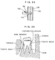
- the electric toothbrush 100 is used as follows. While the user is gripping the handle 112, the user holds the temporary positioning member 154 against the occlusal area of the crown 190 of a tooth T for thereby positioning the tip ends of the bristles 146 of the bristle assembly 116 in abutment against the tooth side to the tooth neck 192 of the tooth T, as shown in FIGS. 24 and 29.
- the user turns on the switch 180 on the handle 112 to cause the small motor 176 of the actuator 168 to rotate the rotatable shaft 126 in the casing 114.
- the swing shafts 128 of the reciprocally rocking mechanism 118 are moved vertically, causing the bristle bases 142 of the bristle assembly 116 coupled to the swing shafts 128 to angularly move reciprocally.
- the tip ends of the bristles 146 are angularly moved reciprocally in a manner to turn upwardly to scrape off plaque 194 deposited on the tooth side and the tooth neck without pushing the plaque into a gum groove 196.
- the bristles 146 are also effective to massage the gum 198.
- the temporary positioning member 154 of the casing 114 is moved along the occlusal areas of upper and lower teeth in abutment thereagainst for thereby removing plaque deposited on the tooth side and the tooth neck of each tooth T.
- the cylindrical member 170 of the handle 112 is fitted over the joint sleeve 164 on the other end of the casing 114.
- the gum is pevented from being peeled off the tooth necks, and hence can be maintained in a healthy condition for protection against periodontites and dental caries.
- each brush base 142 may be pivotally coupled to the swing shafts 128 in the vertical case 120 and the sides of each brush base 142 may be pivotally mounted in a lateral hole 184 defined in the inner side wall of the vertical case 120.
- the brush base 142 is angularly moved to cause the bristles 146 on the end of the brush base 142 to remove plaque and tartar deposited on the tooth side and the tooth neck of each tooth T.
- the casing 114 may not necessarily be limited to an inverted L shape, but may be of a shape spreading at an obtuse angle. Furthermore, only the vertical case 120 may serve as a casing with the bristle assembly 116 housed therein. Such an arrangement is easier to use.
Landscapes
- Health & Medical Sciences (AREA)
- General Health & Medical Sciences (AREA)
- Dentistry (AREA)
- Public Health (AREA)
- Animal Behavior & Ethology (AREA)
- Life Sciences & Earth Sciences (AREA)
- Epidemiology (AREA)
- Veterinary Medicine (AREA)
- Engineering & Computer Science (AREA)
- Manufacturing & Machinery (AREA)
- Mechanical Engineering (AREA)
- Brushes (AREA)
- Dental Tools And Instruments Or Auxiliary Dental Instruments (AREA)
Claims (20)
- Zahnbürste (A1-A7; 100), umfassend:einen Griffstiel (1; 5; 112), undeinen Kopf (2; 2a; 2b; 92a/92b/92c; 114), welcher an einem distalen Ende des Griffstiels angebracht ist,
wobei der Kopf (2; 2a; 2b; 92a/92b/92c; 114) derart aufgebaut ist, daß er an einem Zahn in einer umgreifenden Weise angreift, und eine Borstenanordnung (3/3a; 3'/3a'; 94; 116) mit Borsten (41, 146) aufweist, welche Borsten derart angeordnet sind, daß sie an einer Seite des Zahns in einem spitzen Winkel angreifen;
dadurch gekennzeichnet,daß die Borsten derart geneigt sind, daß sie von der Wurzel des Zahns weg und zur Spitze seiner Krone hin weisen. - Zahnbürste (A1-A7; 100) nach Anspruch 1, wobei der Winkel im Bereich von 30° bis 60° liegt.
- Zahnbürste (A1; A2; A3; 100) nach Anspruch 1, wobei der Kopf (2; 114) einen im wesentlichen L-förmigen Querschnitt aufweist, wobei die Borstenanordnung (3/3a; 116) an der Innenseite von einem (21, 120) von Flügeln (21, 22; 120, 122) des Kopfes befestigt ist, wobei der eine der Flügel derart angeordnet ist, daß er sich im wesentlichen parallel zur Seite des Zahns erstreckt, und wobei die Borsten (41, 146) der Borstenanordnung sich zu einer Winkelecke des L-förmigen Kopfes hin erstrecken.
- Zahnbürste (A2) nach Anspruch 1, 2 oder 3, wobei der Griffstiel (5) einen an diesem angebrachten Stielschaft (1a) aufweist für eine Hin- und Her-Winkelbewegung zumindest um eine Achse des Griffstiels (5) oder in der Richtung einer Zahnachse oder in der zu der Richtung der Zahnachse normalen Richtung durch ein elektrisches Stellgliedmittel (51, 52, 53), welches im Griffstiel (5) untergebracht ist.
- Zahnbürste (A1, A2) nach Anspruch 3 oder 4, wobei der Kopf (2) ein Einstellmittel (25) aufweist zum Einstellen des Vorstehens der an der Innenfläche des anderen (22) der Flügel (21, 22) befestigten Borstenanordnung (3a), wobei der andere (22) der Flügel (21, 22) derart angeordnet ist, daß er sich im wesentlichen orthogonal zu der Seite des Zahns erstreckt.
- Zahnbürste (A1, A2) nach einem der Ansprüche 3 bis 5, wobei der Kopf (2) Anbringmittel (20) zum entfernbaren Anbringen eines distalen Endes des Griffstiels (1) oder eines Stielschafts (1a) an einem Längsende des Kopfes (2) aufweist.
- Zahnbürste (A4, A5) nach Anspruch 1 oder 2, wobei der Kopf (2/2a) einen Backenzahn-angepaßten Abschnitt (90) mit einer zu einer Backenzahnoberfläche korrespondierenden Innenwandung aufweist, wobei die Borstenanordnung (3') an der Innenwandung des Backenzahnangepaßten Abschnitts (90) befestigt ist.
- Zahnbürste (A4, A5) nach Anspruch 7, wobei der Kopf (2) ferner einen Vorderzahn-angepaßten Abschnitt (91) mit einer zu einer Vorderzahnoberfläche korrespondierenden Innenwandung und eine weitere Borstenanordnung (3a') aufweist, welche ebenfalls an der Innenwandung des Vorderzahn-angepaßten Abschnitts (91) befestigt ist.
- Zahnbürste (A4, A5) nach Anspruch 1 oder 2, wobei der Kopf (2b) einen Vorderzahn-angepaßten Abschnitt (91) mit einer zu einer Vorderzahnoberfläche korrespondierenden Innenwandung aufweist, wobei die Borstenanordnung (3a') an der Innenwandung des Vorderzahnangepaßten Abschnitts (91) befestigt ist.
- Zahnbürste (A5) nach Anspruch 7, 8 oder 9, wobei der Griffstiel (5) einen an diesem angebrachten Stielschaft (1a) aufweist für eine Hin- und Her-Winkelbewegung wenigstens um eine Achse des Griffstiels (5) oder in der Richtung einer Zahnachse oder in der zur Richtung der Zahnachse normalen Richtung durch ein elektrisches Stellgliedmittel (51, 52, 53), welches im Griffstiel (5) untergebracht ist.
- Zahnbürste (A6, A7, A8) nach Anspruch 1 oder 2, wobei der Kopf (92a/ 92b/ 92c) eine Mehrzahl von Kopfkörpern (92a, 92b, 92c) aufweist, welche an einem distalen Ende des Griffstiels (1) angebracht sind.
- Zahnbürste (A6, A7, A8) nach Anspruch 11, wobei die Kopfkörper (92a, 92b, 92c) bezüglich dem distalen Ende des Griffstiels (1) entfernbar sind.
- Zahnbürste (A7, A8) nach Anspruch 11 oder 12, wobei der Griffstiel (5) einen am Griffstiel (5) angebrachten Schwingungserzeuger aufweist zum Erzeugen von Schwingungen in einer vorbestimmten Richtung, verursacht durch ein elektrisches Stellgliedmittel (51, 52, 53), welches in dem Griffstiel (5) untergebracht ist.
- Zahnbürste (100) nach Anspruch 1 oder 2, wobei die Borstenanordnung (146) derart winkelmäßig und hin- und herbewegbar ist, daß sie zum Kopfende des Zahns hin schwingt, wobei die Zahnbürste (100) ferner Hin- und Her-Schwenkmittel (118) zum winkelmäßigen Bewegen der Borstenanordnungen (156) und ein mit den Hin- und Her-Schwenkmitteln (118) gekoppeltes Stellglied (168) umfaßt.
- Zahnbürste (100) nach Anspruch 14, wobei der Kopf (114) ein im wesentlichen L-förmiges Gehäuse aufweist mit einem ersten Abschnitt, welcher derart angeordnet ist, daß er sich im wesentlichen parallel zu der Seite des Zahns (120) erstreckt, und einem zweiten Abschnitt (122), welcher derart angeordnet ist, daß er sich im wesentlichen orthogonal zu der Seite des Zahns erstreckt, wobei die Borstenanordnung (116) am ersten Abschnitt (120) angeordnet ist, und wobei ein Temporär-Positionierungs-Element (154) zum temporären Positionieren der Borstenanordnung (146) zum Angreifen am Zahn am zweiten Abschnitt (122) angeordnet ist.
- Zahnbürste (100) nach Anspruch 15, wobei das Temporär-Positionierungs-Element (154) ein federndes Material aufweist.
- Zahnbürste (100) nach Anspruch 15, wobei das Temporär-Positionierungs-Element (154) Borsten (146) aufweist.
- Zahnbürste (100) nach Anspruch 15, 16 oder 17, wobei das Temporär-Positionierungs-Element (154) höhenverstellbar ist.
- Zahnbürste (100) nach einem der Ansprüche 14 bis 18, wobei die Borstenanordnung (116) einen oberen Satz von Borsten (146) umfaßt, welcher derart angeordnet ist, daß er einen dem Kopfende der Krone benachbarten Bereich der Seite des Zahns bürstet, und einen unteren Satz von Borsten (146) umfaßt, welcher derart angeordnet ist, daß er einen der Wurzel näheren Bereich der Seite des Zahns bürstet, wobei der untere Satz von Borsten (146) länger als der obere Satz von Borsten (146) ist.
- Zahnbürste (100) nach einem der Ansprüche 14 bis 18, wobei die Borstenanordnung (116) einen oberen Satz von Borsten (146) umfaßt, welcher derart angeordnet ist, daß er einen dem Kopf der Krone benachbarten Bereich der Seite des Zahns bürstet, einen mittleren Satz von Borsten und einen unteren Satz von Borsten (146) aufweist, welche derart angeordnet sind, daß sie Bereiche der Seite des Zahns bürsten, welche jeweils näher an der Wurzel liegen, wobei die Borsten (146) vom unteren Satz über den mittleren Satz zum oberen Satz aufeinanderfolgend längere, kürzere und mittlere Längen aufweisen.
Applications Claiming Priority (9)
| Application Number | Priority Date | Filing Date | Title |
|---|---|---|---|
| JP316113/92 | 1992-10-31 | ||
| JP31611392A JP2533441B2 (ja) | 1992-10-31 | 1992-10-31 | 電動歯ブラシ |
| JP345559/92 | 1992-11-30 | ||
| JP34555992A JP2533443B2 (ja) | 1992-11-30 | 1992-11-30 | 歯ブラシ |
| JP36053392A JP2533445B2 (ja) | 1992-12-29 | 1992-12-29 | 歯ブラシおよび電動歯ブラシ |
| JP360533/92 | 1992-12-29 | ||
| JP273202/93 | 1993-10-04 | ||
| JP27320293A JP2781861B2 (ja) | 1993-10-04 | 1993-10-04 | 歯ブラシおよび電動歯ブラシ |
| PCT/JP1993/001561 WO1994009676A1 (fr) | 1992-10-31 | 1993-10-28 | Brosse a dents manuelle et brosse a dents electrique |
Publications (3)
| Publication Number | Publication Date |
|---|---|
| EP0669091A1 EP0669091A1 (de) | 1995-08-30 |
| EP0669091A4 EP0669091A4 (de) | 1997-10-01 |
| EP0669091B1 true EP0669091B1 (de) | 1999-04-07 |
Family
ID=27478989
Family Applications (1)
| Application Number | Title | Priority Date | Filing Date |
|---|---|---|---|
| EP93923657A Expired - Lifetime EP0669091B1 (de) | 1992-10-31 | 1993-10-28 | ZAHNBüRSTE UND ELEKTRISCH ANGETRIEBENE ZAHNBüRSTE |
Country Status (11)
| Country | Link |
|---|---|
| US (3) | US5842249A (de) |
| EP (1) | EP0669091B1 (de) |
| KR (3) | KR100236404B1 (de) |
| AT (1) | ATE178468T1 (de) |
| AU (1) | AU674714B2 (de) |
| CA (1) | CA2147465C (de) |
| DE (1) | DE69324373T2 (de) |
| DK (1) | DK0669091T3 (de) |
| ES (1) | ES2129523T3 (de) |
| GR (1) | GR3030423T3 (de) |
| WO (1) | WO1994009676A1 (de) |
Families Citing this family (73)
| Publication number | Priority date | Publication date | Assignee | Title |
|---|---|---|---|---|
| US5987688A (en) | 1995-11-09 | 1999-11-23 | Gillette Canada Inc. | Gum-massaging oral brush |
| US6564940B2 (en) | 1998-09-30 | 2003-05-20 | The Procter & Gamble Company | Electric toothbrush |
| US6371294B1 (en) | 1998-09-30 | 2002-04-16 | The Procter & Gamble Company | Electric toothbrush |
| US6178579B1 (en) | 1998-09-30 | 2001-01-30 | Dr. Johns Products, Ltd. | Electric toothbrush |
| USD456998S1 (en) | 1999-01-25 | 2002-05-14 | Lawrence A. Blaustein | Head portion of an electric toothbrush |
| US6401288B1 (en) * | 1999-04-23 | 2002-06-11 | Robert P. Porper | Mechanical toothbrush with opposed dual heads and having oscillatory movement |
| US6381794B1 (en) * | 1999-04-23 | 2002-05-07 | Robert P. Porper | Electric toothbrush having dual heads with oscillatory movement |
| US6574820B1 (en) | 1999-10-22 | 2003-06-10 | The Gillette Company | Brush head for toothbrush |
| US6553604B1 (en) | 2000-03-16 | 2003-04-29 | Gillette Canada Company | Toothbrush |
| US6823554B1 (en) | 2000-10-05 | 2004-11-30 | Gillette Canada Company | Oral devices |
| US6453501B1 (en) | 2000-12-29 | 2002-09-24 | Theresa Della Bella | Animal toothbrush |
| US6536065B2 (en) * | 2001-02-26 | 2003-03-25 | Andrea Forrest | Multi-brush ultrasonic nail cleaner |
| GB2377167A (en) * | 2001-07-04 | 2003-01-08 | Kais As-Sultany | Toothbrush |
| US6625834B2 (en) | 2001-10-09 | 2003-09-30 | Peter W. Dean | Manual toothbrush for gingival tissue stimulation |
| US6725490B2 (en) | 2001-11-06 | 2004-04-27 | The Procter & Gamble Company | Complex motion toothbrush |
| US20030084526A1 (en) * | 2001-11-06 | 2003-05-08 | The Procter & Gamble Co. | Multi-motion toothbrush |
| EP1441665B1 (de) * | 2001-11-06 | 2012-03-21 | The Procter & Gamble Company | Mehrfach bewegliche zahnbürste |
| US20030084527A1 (en) * | 2001-11-06 | 2003-05-08 | The Procter & Gamble Co. | Multi-motion toothbrush |
| GB0129780D0 (en) * | 2001-12-13 | 2002-01-30 | Daniels Seymour C | Perfect polisher/hany hairbrush/super sweeper |
| USD499884S1 (en) | 2002-03-15 | 2004-12-21 | The Procter & Gamble Company | Electric toothbrush |
| AU2003209641A1 (en) * | 2002-04-08 | 2003-10-27 | Verifresh Ltd. | Gum massager device |
| US20030196283A1 (en) * | 2002-04-23 | 2003-10-23 | Eyal Eliav | Powered toothbrush |
| US6785926B2 (en) * | 2002-05-09 | 2004-09-07 | Carl Green | Mechanically-driven toothbrush with improved brushing action |
| US20110308024A1 (en) * | 2002-06-03 | 2011-12-22 | Hegemann Kenneth J | Oral Brushing Devices and/or Methods |
| US6931688B2 (en) | 2002-08-09 | 2005-08-23 | Colgate-Palmolive Company | Toothbrush |
| US7055531B2 (en) | 2004-07-07 | 2006-06-06 | Rehco, Llc | Electronic oral cleaning device |
| USD536876S1 (en) | 2003-02-03 | 2007-02-20 | Church & Dwight Co., Inc. | Head portion of a toothbrush |
| US20040177458A1 (en) | 2003-03-10 | 2004-09-16 | The Procter & Gamble Company | Electric toothbrushes |
| AU2008200508B2 (en) * | 2003-03-14 | 2011-03-31 | The Gillette Company Llc | Toothbrush head |
| US20060272112A9 (en) | 2003-03-14 | 2006-12-07 | The Gillette Company | Toothbrush |
| US20040177462A1 (en) | 2003-03-14 | 2004-09-16 | The Gillette Company | Toothbrush head |
| USD728118S1 (en) | 2003-03-17 | 2015-04-28 | Verifresh Ltd | Gum massager |
| CA2644304C (en) * | 2003-04-23 | 2011-06-21 | John Geoffrey Chan | Electric toothbrushes |
| US20090044357A1 (en) * | 2007-08-16 | 2009-02-19 | The Procter & Gamble Company | Electric toothbrushes |
| US7941886B2 (en) | 2003-09-19 | 2011-05-17 | Braun Gmbh | Toothbrushes |
| US7044737B2 (en) * | 2004-03-05 | 2006-05-16 | Liang Fu | Ultrasound oral hygiene and therapeutic device |
| CN1878511A (zh) * | 2004-03-18 | 2006-12-13 | 瓦列里·弗拉基米罗维奇·库兹涅特索夫 | 电动牙刷的清洁头部 |
| DE102004036812A1 (de) | 2004-07-29 | 2006-03-23 | Braun Gmbh | Elektrische Zahnbürste |
| US7694419B2 (en) * | 2005-04-27 | 2010-04-13 | The Gillette Company | Battery-operated appliances |
| US20070079459A1 (en) * | 2005-10-06 | 2007-04-12 | Bradford Brian W | Multi base contact device |
| DE102005059775A1 (de) * | 2005-12-14 | 2007-06-28 | Schaaf, Gunnar, Dr. med. dent. | Vorrichtung zum Reinigen von Zähnen |
| USD542541S1 (en) | 2006-09-20 | 2007-05-15 | Lowsky Jr John | Brush tip |
| US20080250583A1 (en) * | 2007-04-10 | 2008-10-16 | Carl Green | Motor-powered toothbrush with improved brushing action |
| CH699069A2 (de) * | 2008-07-02 | 2010-01-15 | Hasan Hueseyin Isik | Zahnbürste. |
| US20100263150A1 (en) * | 2009-04-17 | 2010-10-21 | Tessema Dosho Shifferaw | Toothbrush |
| US8117707B1 (en) * | 2009-05-26 | 2012-02-21 | Ruh Ii Gary Robert | Pool cage beam brush |
| US8745804B2 (en) * | 2009-08-27 | 2014-06-10 | Steven Jaksha | Stainless steel toothbrush with thermochromic display |
| US20130067670A1 (en) * | 2009-10-01 | 2013-03-21 | Michael Liangco | FlexibleToothbrush |
| US20110078867A1 (en) * | 2009-10-01 | 2011-04-07 | Michael Liangco | Flexible toothbrush |
| US20110113576A1 (en) * | 2009-11-17 | 2011-05-19 | Yankell Samuel L | Toothbrush with movable head |
| US20110191971A1 (en) * | 2010-02-07 | 2011-08-11 | Pin Zeng | H Shape Toothbrush |
| TWM417831U (en) * | 2011-01-20 | 2011-12-11 | jia-xiang Zhang | Toothbrush with large area of bristle |
| BR112014000651A2 (pt) | 2011-07-12 | 2017-02-14 | Colgate Palmolive Co | escova de dente oscilatória e vibratória e cabeça de recarga para a mesma |
| BR112014014908A2 (pt) * | 2011-12-22 | 2017-06-13 | Koninklijke Philips Nv | cabeça de escova para uma escova de dente elétrica com membros da pá em movimento |
| US8938841B1 (en) | 2012-10-10 | 2015-01-27 | Jose A. Ramirez | Tooth brushing system |
| US9339357B1 (en) * | 2014-02-07 | 2016-05-17 | Maxim Babiner | Multi-headed toothbrush |
| US9648942B2 (en) | 2014-08-19 | 2017-05-16 | Regents Of The University Of Minnesota | Toothbrush |
| US10245720B2 (en) | 2014-09-12 | 2019-04-02 | Chris Ptak | Elastic vibrating appliance handle |
| CN105167873B (zh) * | 2015-09-30 | 2017-03-22 | 李海军 | 一种双凹槽旋转式牙刷 |
| US10477838B2 (en) * | 2016-03-28 | 2019-11-19 | Peter Dertsakyan | Pet chew toy for dental self-cleaning by domestic pets |
| USD901104S1 (en) | 2017-03-28 | 2020-11-03 | Peter Dertsakyan | Pet toy and dental hygiene device |
| USD826568S1 (en) * | 2017-05-11 | 2018-08-28 | Gene Sheinkman | Toothbrush |
| JP7280277B2 (ja) * | 2017-11-08 | 2023-05-23 | インジーニアス・インヴェンションズ・インコーポレイテッド | 化粧料塗布具及びそれを使用する方法 |
| BR112020016408B1 (pt) | 2018-02-13 | 2023-03-14 | Eht Llc | Aparelho para irrigação dentária |
| USD917174S1 (en) * | 2019-04-18 | 2021-04-27 | Anthony Christian Clark | Toothbrush |
| CN110640967A (zh) * | 2019-08-30 | 2020-01-03 | 福清市华天广告有限公司 | 教学用牙周外科模型成形器及其使用方法 |
| CN116033849B (zh) * | 2020-07-03 | 2026-01-27 | 埃里昂产品有限公司 | 用于清洁牙齿及固定义齿的近中面和远中面的装置 |
| USD959842S1 (en) | 2020-08-26 | 2022-08-09 | Daniel Powell | Toothbrush |
| EP4412556B1 (de) * | 2021-10-08 | 2025-06-04 | Koninklijke Philips N.V. | Mundstück zur mundreinigung |
| US11930918B1 (en) * | 2023-06-27 | 2024-03-19 | John R. Boren | Personal care implements |
| US20250009115A1 (en) * | 2023-07-08 | 2025-01-09 | Ok Rim Suh | Effective and timesaving toothbrush |
| USD1120325S1 (en) | 2024-02-16 | 2026-03-24 | Chase Boeker | Oral care product |
| DE102024107669A1 (de) * | 2024-03-18 | 2025-09-18 | epitome GmbH | Verfahren und Vorrichtung zum Positionieren von Einrichtungen im Mundraum |
Family Cites Families (47)
| Publication number | Priority date | Publication date | Assignee | Title |
|---|---|---|---|---|
| GB190209632A (en) * | 1902-04-25 | 1902-05-29 | Elisabeth Gaitzsch-Nee-Morenz | Improvements in Tooth Brushes. |
| US887181A (en) * | 1907-07-22 | 1908-05-12 | Elias D Barnes | Tooth-brush. |
| US1270233A (en) * | 1918-03-02 | 1918-06-18 | Max Stoorman | Rotary tooth-brush. |
| FR588348A (fr) * | 1924-10-31 | 1925-05-05 | Double brosse à dents | |
| US1709262A (en) * | 1927-09-02 | 1929-04-16 | Vincent H Henderhan | Toothbrush |
| US1707118A (en) * | 1927-10-10 | 1929-03-26 | Goldberg Abraham | Toothbrush |
| US1830995A (en) * | 1929-10-05 | 1931-11-10 | Benjamin H Genn | Toothbrush |
| US1868368A (en) * | 1931-07-25 | 1932-07-19 | Weston B Reese | Toothbrush |
| GB402293A (en) * | 1932-12-13 | 1933-11-30 | Emil Rudolph Walter Hebbel | Tooth brush |
| CH175862A (fr) * | 1933-12-06 | 1935-03-15 | Vachoux William | Outillage pour se brosser les dents. |
| US2066241A (en) * | 1935-06-17 | 1936-12-29 | Trattner | Tooth brush |
| US2093383A (en) * | 1935-10-15 | 1937-09-14 | Rudof | Tooth brush |
| US2214407A (en) * | 1936-12-05 | 1940-09-10 | Wilhelm Ernst Reeser | Toothbrush with brush head made in three parts |
| GB483939A (en) * | 1937-02-17 | 1938-04-28 | August Andreas Deutsch | Improvements in and relating to tooth-brushes |
| US2588601A (en) * | 1950-02-06 | 1952-03-11 | Alfred E Zavagno | Spring pressed toothbrush |
| DE825536C (de) * | 1950-06-02 | 1951-12-20 | Hans Haeusser | Zahnbuerste |
| US2701380A (en) * | 1950-07-14 | 1955-02-08 | Sophia T Ripper | Attachment for toothbrushes |
| US2682066A (en) * | 1953-01-27 | 1954-06-29 | Clifford D Keely | Mechanical toothbrush with opposed oscillatory brushes |
| US2771624A (en) * | 1955-02-23 | 1956-11-27 | Tri Dent Corp | Toothbrush |
| FR1126824A (fr) * | 1955-06-29 | 1956-12-03 | Brosse à dents | |
| US3065479A (en) * | 1962-01-19 | 1962-11-27 | Joseph E Mcgee | Toothbrushes |
| US3683442A (en) * | 1971-04-05 | 1972-08-15 | Hollymatic Corp | Toothbrush |
| US4131967A (en) * | 1976-02-03 | 1979-01-02 | Northemann Karl Heinz | Toothbrush |
| JPS5548978Y2 (de) * | 1977-11-25 | 1980-11-15 | ||
| JPS5483976A (en) * | 1977-12-19 | 1979-07-04 | Bridgestone Tire Co Ltd | Method of repair ununiformity of tire |
| US4223417A (en) * | 1979-01-31 | 1980-09-23 | Solow Terry S | Gliding, mechanized toothbrush |
| FR2489119A1 (fr) * | 1980-08-29 | 1982-03-05 | Pelosse Andre | Brosse a dents a usage domestique |
| JPS5786307A (en) * | 1980-11-15 | 1982-05-29 | Matsushita Electric Works Ltd | Electromotive tooth brush |
| US4375115A (en) * | 1981-10-07 | 1983-03-01 | Zimmerman Robert W | Exhaust stack cleaning and polishing implement |
| CA1216714A (fr) * | 1982-08-24 | 1987-01-20 | Frederic Barth | Appareil d'hygiene dentaire comprenant plusieurs brosses rotatives |
| DE3301668A1 (de) | 1983-01-20 | 1984-07-26 | Metallgesellschaft Ag, 6000 Frankfurt | Regelverfahren fuer eine entstaubungsanlage |
| JPS6155963A (ja) * | 1984-08-28 | 1986-03-20 | Toshiba Corp | 半導体装置 |
| JPS6186038A (ja) * | 1984-10-04 | 1986-05-01 | Enbishi Arumihoiile Kk | 組立式ホイ−ルにおけるリムの製造方法 |
| JPS6186038U (de) * | 1984-11-09 | 1986-06-05 | ||
| JPS61156526A (ja) * | 1984-12-28 | 1986-07-16 | Fujitsu Ltd | 磁気デイスクの製造方法 |
| US4757570A (en) * | 1985-06-18 | 1988-07-19 | Manfred Haeusser | Toothbrush for simultaneous cleaning of teeth on both sides |
| JPS6235525U (de) * | 1985-08-22 | 1987-03-02 | ||
| JPS62136826A (ja) * | 1985-12-11 | 1987-06-19 | Fujitsu Ltd | 半導体装置の製造方法 |
| JPS62136826U (de) * | 1986-02-22 | 1987-08-28 | ||
| MX169377B (es) * | 1986-12-04 | 1993-06-30 | Ronald William Klinkhammer | Dispositivo y metodo para la limpieza de dientes |
| US5137039A (en) * | 1991-03-04 | 1992-08-11 | Focus Development Corporation, Inc. | Tooth cleaning device |
| WO1989001303A1 (fr) * | 1987-08-21 | 1989-02-23 | Haeusser Manfred | Brosse a dents de massage |
| USD315450S (en) * | 1988-11-25 | 1991-03-19 | Wagner Eugene C | Toothbrush |
| US5072481A (en) * | 1989-11-13 | 1991-12-17 | Frank Weyer | Multi-surface toothbrush |
| CA2056858C (en) * | 1991-11-07 | 2000-07-18 | Kenneth J. Hegemann | Self-adjusting three sided toothbrush and method of manufacture |
| GB9200154D0 (en) * | 1992-01-06 | 1992-02-26 | Chung Angelika Y B | A toothbrush |
| US5499421A (en) * | 1993-06-15 | 1996-03-19 | Brice; Michael F. | Twin-headed toothbrush |
-
1993
- 1993-10-28 EP EP93923657A patent/EP0669091B1/de not_active Expired - Lifetime
- 1993-10-28 KR KR1019970706375A patent/KR100236404B1/ko not_active Expired - Fee Related
- 1993-10-28 DK DK93923657T patent/DK0669091T3/da active
- 1993-10-28 AU AU53446/94A patent/AU674714B2/en not_active Ceased
- 1993-10-28 ES ES93923657T patent/ES2129523T3/es not_active Expired - Lifetime
- 1993-10-28 KR KR1019950701677A patent/KR0127992B1/ko not_active Expired - Fee Related
- 1993-10-28 KR KR1019950701677A patent/KR950703881A/ko active Granted
- 1993-10-28 CA CA002147465A patent/CA2147465C/en not_active Expired - Fee Related
- 1993-10-28 AT AT93923657T patent/ATE178468T1/de not_active IP Right Cessation
- 1993-10-28 WO PCT/JP1993/001561 patent/WO1994009676A1/ja not_active Ceased
- 1993-10-28 DE DE69324373T patent/DE69324373T2/de not_active Expired - Fee Related
-
1997
- 1997-10-28 US US08/963,114 patent/US5842249A/en not_active Expired - Fee Related
-
1998
- 1998-05-26 US US09/084,098 patent/US6209164B1/en not_active Expired - Fee Related
-
1999
- 1999-06-03 GR GR990401507T patent/GR3030423T3/el unknown
-
2000
- 2000-06-30 US US09/609,252 patent/US6334232B1/en not_active Expired - Fee Related
Also Published As
| Publication number | Publication date |
|---|---|
| DK0669091T3 (da) | 1999-10-18 |
| EP0669091A4 (de) | 1997-10-01 |
| CA2147465C (en) | 2003-03-18 |
| ES2129523T3 (es) | 1999-06-16 |
| EP0669091A1 (de) | 1995-08-30 |
| CA2147465A1 (en) | 1994-05-01 |
| US5842249A (en) | 1998-12-01 |
| KR0127992B1 (ko) | 1998-04-06 |
| KR19980702967A (ko) | 1998-09-05 |
| HK1017804A1 (en) | 1999-11-26 |
| ATE178468T1 (de) | 1999-04-15 |
| WO1994009676A1 (fr) | 1994-05-11 |
| AU674714B2 (en) | 1997-01-09 |
| GR3030423T3 (en) | 1999-09-30 |
| KR950703881A (ko) | 1995-11-17 |
| AU5344694A (en) | 1994-05-24 |
| DE69324373T2 (de) | 1999-08-26 |
| KR100236404B1 (ko) | 1999-12-15 |
| DE69324373D1 (de) | 1999-05-12 |
| US6209164B1 (en) | 2001-04-03 |
| US6334232B1 (en) | 2002-01-01 |
Similar Documents
| Publication | Publication Date | Title |
|---|---|---|
| EP0669091B1 (de) | ZAHNBüRSTE UND ELEKTRISCH ANGETRIEBENE ZAHNBüRSTE | |
| US20020152563A1 (en) | Toothbrush and electric toothbrush | |
| RU2323671C2 (ru) | Зубная щетка | |
| AU2003267085B2 (en) | Powered toothbrush | |
| CN100398033C (zh) | 牙刷 | |
| US7954193B2 (en) | Oral brushing devices and/or methods | |
| US5398366A (en) | Rocker toothbrush | |
| US6381794B1 (en) | Electric toothbrush having dual heads with oscillatory movement | |
| EP0585408A4 (en) | Rocker toothbrush | |
| AU2004216121B2 (en) | Powered toothbrush with improved ergonomics | |
| US7757329B2 (en) | Oral brushing devices and/or methods | |
| JP2000511790A (ja) | 横歯ブラシ | |
| GB2025216A (en) | Rotary toothbrush | |
| US4534081A (en) | Tooth cleaning bristle and holder | |
| CN1725964B (zh) | 具有独特手柄的电动牙刷 | |
| HK1017804B (en) | Toothbrush and electric toothbrush | |
| JP2533443B2 (ja) | 歯ブラシ | |
| JP2533441B2 (ja) | 電動歯ブラシ | |
| JP2676335B2 (ja) | 歯ブラシ | |
| JP2533445B2 (ja) | 歯ブラシおよび電動歯ブラシ | |
| JPH02206403A (ja) | 口腔内ブラシ | |
| KR20010103972A (ko) | 전동 칫솔 | |
| US20040226120A1 (en) | Powered toothbrush with curved neck, flexible shaft and tapered head | |
| HK1110757A (en) | Toothbrush |
Legal Events
| Date | Code | Title | Description |
|---|---|---|---|
| PUAI | Public reference made under article 153(3) epc to a published international application that has entered the european phase |
Free format text: ORIGINAL CODE: 0009012 |
|
| 17P | Request for examination filed |
Effective date: 19950531 |
|
| AK | Designated contracting states |
Kind code of ref document: A1 Designated state(s): AT BE CH DE DK ES FR GB GR IE IT LI LU MC NL PT SE |
|
| A4 | Supplementary search report drawn up and despatched |
Effective date: 19970818 |
|
| AK | Designated contracting states |
Kind code of ref document: A4 Designated state(s): AT BE CH DE DK ES FR GB GR IE IT LI LU MC NL PT SE |
|
| 17Q | First examination report despatched |
Effective date: 19971016 |
|
| GRAG | Despatch of communication of intention to grant |
Free format text: ORIGINAL CODE: EPIDOS AGRA |
|
| GRAG | Despatch of communication of intention to grant |
Free format text: ORIGINAL CODE: EPIDOS AGRA |
|
| GRAH | Despatch of communication of intention to grant a patent |
Free format text: ORIGINAL CODE: EPIDOS IGRA |
|
| GRAH | Despatch of communication of intention to grant a patent |
Free format text: ORIGINAL CODE: EPIDOS IGRA |
|
| GRAA | (expected) grant |
Free format text: ORIGINAL CODE: 0009210 |
|
| AK | Designated contracting states |
Kind code of ref document: B1 Designated state(s): AT BE CH DE DK ES FR GB GR IE IT LI LU MC NL PT SE |
|
| REF | Corresponds to: |
Ref document number: 178468 Country of ref document: AT Date of ref document: 19990415 Kind code of ref document: T |
|
| REG | Reference to a national code |
Ref country code: CH Ref legal event code: NV Representative=s name: A. BRAUN, BRAUN, HERITIER, ESCHMANN AG PATENTANWAE Ref country code: CH Ref legal event code: EP |
|
| REG | Reference to a national code |
Ref country code: IE Ref legal event code: FG4D |
|
| ET | Fr: translation filed | ||
| REF | Corresponds to: |
Ref document number: 69324373 Country of ref document: DE Date of ref document: 19990512 |
|
| REG | Reference to a national code |
Ref country code: ES Ref legal event code: FG2A Ref document number: 2129523 Country of ref document: ES Kind code of ref document: T3 |
|
| REG | Reference to a national code |
Ref country code: PT Ref legal event code: SC4A Free format text: AVAILABILITY OF NATIONAL TRANSLATION Effective date: 19990519 |
|
| REG | Reference to a national code |
Ref country code: DK Ref legal event code: T3 |
|
| PLBE | No opposition filed within time limit |
Free format text: ORIGINAL CODE: 0009261 |
|
| STAA | Information on the status of an ep patent application or granted ep patent |
Free format text: STATUS: NO OPPOSITION FILED WITHIN TIME LIMIT |
|
| 26N | No opposition filed | ||
| PG25 | Lapsed in a contracting state [announced via postgrant information from national office to epo] |
Ref country code: MC Free format text: LAPSE BECAUSE OF NON-PAYMENT OF DUE FEES Effective date: 20000430 |
|
| PGFP | Annual fee paid to national office [announced via postgrant information from national office to epo] |
Ref country code: GB Payment date: 20011024 Year of fee payment: 9 |
|
| PGFP | Annual fee paid to national office [announced via postgrant information from national office to epo] |
Ref country code: FR Payment date: 20011025 Year of fee payment: 9 Ref country code: IE Payment date: 20011025 Year of fee payment: 9 |
|
| PGFP | Annual fee paid to national office [announced via postgrant information from national office to epo] |
Ref country code: DE Payment date: 20011026 Year of fee payment: 9 Ref country code: CH Payment date: 20011026 Year of fee payment: 9 |
|
| PGFP | Annual fee paid to national office [announced via postgrant information from national office to epo] |
Ref country code: SE Payment date: 20011029 Year of fee payment: 9 Ref country code: NL Payment date: 20011029 Year of fee payment: 9 Ref country code: DK Payment date: 20011029 Year of fee payment: 9 |
|
| PGFP | Annual fee paid to national office [announced via postgrant information from national office to epo] |
Ref country code: PT Payment date: 20011030 Year of fee payment: 9 Ref country code: LU Payment date: 20011030 Year of fee payment: 9 Ref country code: AT Payment date: 20011030 Year of fee payment: 9 |
|
| PGFP | Annual fee paid to national office [announced via postgrant information from national office to epo] |
Ref country code: GR Payment date: 20011031 Year of fee payment: 9 Ref country code: ES Payment date: 20011031 Year of fee payment: 9 |
|
| PGFP | Annual fee paid to national office [announced via postgrant information from national office to epo] |
Ref country code: BE Payment date: 20011116 Year of fee payment: 9 |
|
| REG | Reference to a national code |
Ref country code: GB Ref legal event code: IF02 |
|
| PG25 | Lapsed in a contracting state [announced via postgrant information from national office to epo] |
Ref country code: LU Free format text: LAPSE BECAUSE OF NON-PAYMENT OF DUE FEES Effective date: 20021028 Ref country code: IE Free format text: LAPSE BECAUSE OF NON-PAYMENT OF DUE FEES Effective date: 20021028 Ref country code: GB Free format text: LAPSE BECAUSE OF NON-PAYMENT OF DUE FEES Effective date: 20021028 Ref country code: AT Free format text: LAPSE BECAUSE OF NON-PAYMENT OF DUE FEES Effective date: 20021028 |
|
| PG25 | Lapsed in a contracting state [announced via postgrant information from national office to epo] |
Ref country code: SE Free format text: LAPSE BECAUSE OF NON-PAYMENT OF DUE FEES Effective date: 20021029 Ref country code: ES Free format text: LAPSE BECAUSE OF NON-PAYMENT OF DUE FEES Effective date: 20021029 |
|
| PG25 | Lapsed in a contracting state [announced via postgrant information from national office to epo] |
Ref country code: LI Free format text: LAPSE BECAUSE OF NON-PAYMENT OF DUE FEES Effective date: 20021031 Ref country code: DK Free format text: LAPSE BECAUSE OF NON-PAYMENT OF DUE FEES Effective date: 20021031 Ref country code: CH Free format text: LAPSE BECAUSE OF NON-PAYMENT OF DUE FEES Effective date: 20021031 Ref country code: BE Free format text: LAPSE BECAUSE OF NON-PAYMENT OF DUE FEES Effective date: 20021031 |
|
| BERE | Be: lapsed |
Owner name: *SATO MASANORI Effective date: 20021031 |
|
| PG25 | Lapsed in a contracting state [announced via postgrant information from national office to epo] |
Ref country code: PT Free format text: LAPSE BECAUSE OF NON-PAYMENT OF DUE FEES Effective date: 20030430 |
|
| PG25 | Lapsed in a contracting state [announced via postgrant information from national office to epo] |
Ref country code: NL Free format text: LAPSE BECAUSE OF NON-PAYMENT OF DUE FEES Effective date: 20030501 Ref country code: DE Free format text: LAPSE BECAUSE OF NON-PAYMENT OF DUE FEES Effective date: 20030501 |
|
| PG25 | Lapsed in a contracting state [announced via postgrant information from national office to epo] |
Ref country code: GR Free format text: LAPSE BECAUSE OF NON-PAYMENT OF DUE FEES Effective date: 20030506 |
|
| EUG | Se: european patent has lapsed | ||
| REG | Reference to a national code |
Ref country code: DK Ref legal event code: EBP |
|
| REG | Reference to a national code |
Ref country code: CH Ref legal event code: PL |
|
| GBPC | Gb: european patent ceased through non-payment of renewal fee | ||
| PG25 | Lapsed in a contracting state [announced via postgrant information from national office to epo] |
Ref country code: FR Free format text: LAPSE BECAUSE OF NON-PAYMENT OF DUE FEES Effective date: 20030630 |
|
| NLV4 | Nl: lapsed or anulled due to non-payment of the annual fee |
Effective date: 20030501 |
|
| REG | Reference to a national code |
Ref country code: IE Ref legal event code: MM4A |
|
| REG | Reference to a national code |
Ref country code: FR Ref legal event code: ST |
|
| REG | Reference to a national code |
Ref country code: ES Ref legal event code: FD2A Effective date: 20031112 |
|
| PG25 | Lapsed in a contracting state [announced via postgrant information from national office to epo] |
Ref country code: IT Free format text: LAPSE BECAUSE OF NON-PAYMENT OF DUE FEES Effective date: 20051028 |