EP0669232A1 - Tendeur de ceinture de sécurité - Google Patents
Tendeur de ceinture de sécurité Download PDFInfo
- Publication number
- EP0669232A1 EP0669232A1 EP94102751A EP94102751A EP0669232A1 EP 0669232 A1 EP0669232 A1 EP 0669232A1 EP 94102751 A EP94102751 A EP 94102751A EP 94102751 A EP94102751 A EP 94102751A EP 0669232 A1 EP0669232 A1 EP 0669232A1
- Authority
- EP
- European Patent Office
- Prior art keywords
- belt tensioner
- tensioner according
- locking member
- arm
- force
- Prior art date
- Legal status (The legal status is an assumption and is not a legal conclusion. Google has not performed a legal analysis and makes no representation as to the accuracy of the status listed.)
- Granted
Links
Images




Classifications
-
- B—PERFORMING OPERATIONS; TRANSPORTING
- B60—VEHICLES IN GENERAL
- B60R—VEHICLES, VEHICLE FITTINGS, OR VEHICLE PARTS, NOT OTHERWISE PROVIDED FOR
- B60R22/00—Safety belts or body harnesses in vehicles
- B60R22/18—Anchoring devices
- B60R22/195—Anchoring devices with means to tension the belt in an emergency, e.g. means of the through-anchor or splitted reel type
- B60R22/1952—Transmission of tensioning power by cable; Return motion locking means therefor
- B60R22/1953—Transmission of tensioning power by cable; Return motion locking means therefor the cable being pulled by mechanical means, e.g. pre-stressed springs, bumper displacement during crash
Definitions
- the present invention relates to a belt tensioner for the seat belts of vehicles, in which a tension spring by means of a traction device via a locking mechanism with a seat belt part, e.g. a buckle is connected.
- a release mechanism responsive to vehicle decelerations releases the tension spring at predetermined critical deceleration values of the vehicle by means of a lever system, so that the connected seat belt part is retracted and the belt tension takes place, the locking mechanism blocking a backward movement.
- Belt tensioners of this type have the task of tightening an inadequately fastened seat belt in the event of deceleration values of the vehicle, which are characteristic of an imminent accident, so that the person to be secured is already firmly held on the seat by the belt before they due to the inertial forces of your body, take off the belt or use up the loose belt.
- the person to be secured is, as it were, coupled to the seat in the event of an accident, so that it participates in the deceleration of the vehicle from the start.
- the distance that the person to be secured can move forward in relation to the vehicle in an accident is reduced, so that the risk of head or other body parts striking the steering wheel or the windshield or other vehicle parts is eliminated or in any case is significantly reduced.
- the tension by pulling down the belt buckle has proven to be particularly advantageous, since with this type of tension both the lap belt and the shoulder belt are tightened simultaneously.
- the fastening part of the belt buckle moves in a toothed groove of a locking mechanism when the tension spring is triggered (DE 39 37 883, DE 40 13 046, DE 40 20 600).
- the rigidity of the arrangement is disadvantageous, which can result in an unfavorable direction of the force loading of the buckle and the webbing.
- the triggering device is designed such that a lever arm counteracting the force of the tension spring causes the release directly by an over-dead-center movement, with a very high resistance is to be overcome.
- the large friction forces that occur can considerably increase the tripping time, which can be exacerbated by various manufacturing defects.
- the object of the invention is to provide a belt tensioner which triggers quickly and reliably while avoiding the disadvantages mentioned and is relatively inexpensive to manufacture. Furthermore, the belt tensioner should be able to be flexibly adapted for different arrangement cases.
- the release mechanism has
- two rotating bodies preferably two axially parallel rollers, between which a locking member with preferably plane-parallel side surfaces as part of a plunger is arranged displaceably against the force of a control spring, the first roller with its outer surface line being supported against a stationary abutment surface arranged parallel to the locking member surfaces , and the other role in a cutout at the end of a probe arm of the closing lever of the lever system due to the reduced force of the tension spring acted upon, wherein the pressure surface of the cutout of the probe arm runs parallel to the side surfaces of the locking member and the abutment surface and the acting force acts on them in
- the plunger has the shape of a C-shaped bracket, the rear part of which is displaceably guided in a channel of the holder, one leg of which forms the locking member, and the other leg of which represents a foot acted upon by the control spring, the other end of the Control spring is supported by a finger projection on the bracket.
- the rollers are advantageously held in position in the direction of their axis by an ist angled limiting bracket, which is attached to the plunger and thus prevents the rollers from falling out.
- a particularly advantageous embodiment is when the locking member is designed as a short rod with a rectangular cross section and the plunger as a U-shaped bracket, the symmetrical legs of which have opposite rectangular openings at their ends for mounting the locking member, and a limiting plate above the locking member is provided, the legs covering the front ends of the rollers and holding them in position.
- the lower support of the rollers is expediently carried out with respect to the first roller by a projection of the holder and with respect to the other roller by the lower surface of the cutout of the probe arm.
- control spring is expediently supported with one end against a projection of the holder, which has a finger holding this end of the spring in position, and with its other end against the plunger.
- the inertial mass responding to the vehicle deceleration is expediently fastened to one arm of a mass carrier designed as a two-armed lever, the other arm being in constant contact with the plunger and the mass carrier with the inertial mass in the direction of travel in front of the holder, i.e. when viewed in the direction of the vehicle's transverse axis is arranged next to the bracket.
- the upper edge of the cutout of the probe arm is at a greater distance from the line of action in it Starting position located as the distance of the lower surface of the locking member from the line of action in its starting position.
- the locking mechanism interacting with the traction means is expediently a rope pulley which is wrapped around the traction means and which is firmly connected to at least one toothed pulley which interacts with a spring-loaded pawl in such a way that rotation is only possible in the sense of pulling in the traction means.
- the traction means is expediently a rope consisting of two sections, namely a double rope forming a loop on the side of the tension spring, which at a branching point merges into a simple drive rope, the end of which interacts with the tension spring, this tension means wrapping the rope pulley at least once.
- the outer circumference of the traction sheave has a recess into which a steel ring is inserted, which is pressed onto the traction means at the branching point thereof.
- the lever of the lever system which in the rest position of the belt tensioner absorbs the force of the tension spring, has a hook arm, the hook tooth of which can engage in a recess of a mounting bush pressed onto the drive cable.
- a particularly flexible design of the belt tensioner is obtained if the tooth of the hook arm interacts with an abutment element on the circumference of the rope pulley or the toothed pulley.
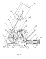
- the supporting base 1 of the belt tensioner according to FIGS. 1 to 5 is a base plate 2, on which a cable pulley 4 is rotatably mounted by means of a pin axis 3.
- a toothed pulley 5 with sawtooth-like locking teeth is riveted to at least one side of this pulley.
- a pivotable pawl 7 interacts, which is held by a leaf spring 8 in engagement with the toothing so that the rope pulley can only rotate counterclockwise.
- a leg 9 is bent laterally, to which a guide tube 10 is fastened, on which a releasable tension spring 11 is placed.
- the belt tensioner includes a belt buckle 12 of conventional construction, which is connected to the pretensioned tension spring 11 by means of a traction means, the traction means wrapping the locking mechanism 14 consisting of the pulley 4 with the toothed pulley 5 by approximately 500 degrees, that is to say in addition to the deflection, a complete loop is realized.
- the traction means consists of a rope which is designed as a simple drive rope 16 towards the tension spring 11 and branches at a branching point to the buckle 12 to a double rope pull 15 which forms a loop 24 which loops around a bolt 25 on the buckle 12.
- a steel ring 17 is pressed, which is inserted into a recess 18 in the circumference of the rope sheave 4. In this way, a positive fixing of the traction cable on the pulley 4 is achieved.
- a steel ring 19 pressed onto the end of the drive cable 16 holds the tension spring 11 in its pretensioned position via a support disk 20.
- a mounting bushing 21 is pressed onto the drive cable 16 and has a recess 23 which forms an abutment surface 22.
- the tensioning force P of the tension spring 11 acts on a hook arm 26 of a first lever 27 of the lever system which is rotatably mounted on the base plate 2, the tooth 28 of the hook arm 26 engaging on the abutment surface 22 of the mounting sleeve 21.
- the other, longer arm of the first lever 27 forms a cam 29 which cooperates with a cam arm 30 of a force-reducing closing lever 31 of the lever system.
- the other longer arm of the closing lever 31 interacts as a trigger arm 32 with the trigger mechanism 33 and has at its end a cutout 34 with surfaces that are perpendicular to one another, namely a pressure surface 35 and a support surface 36 (FIG. 5).
- the axis 37 of the first lever 27 and the axis 38 of the closing lever 31 protrude at right angles from the base plate 2.
- the geometry of the lever system consisting of the first lever 27 and the closing lever 31 is selected so that the force F which the pressure surface 35 of the probe arm 32 exerts on a roller 40 is approximately 1/10 of the force P of the tension spring 11.
- the trigger mechanism 33 is placed on the base plate 2 by means of a holder 39. It includes a first roller 41, which lies on the flat abutment surface 42 of an upright post 43 with an outer surface line, as well as the already mentioned other roller 40, which is freely inserted in the cutout 34 of the probe arm 32.
- the roller 41 is supported from below by a projection 44 formed on the holder 39 and thus secured against falling out.
- the pressure surface 35 of the cutout 34, the side surfaces A and B of the locking member 45 and the abutment surface 42 of the post 43 are preferably oriented parallel to one another. Likewise, these surfaces and the axes of the rollers 40, 41 are oriented at right angles to the base plate 2.
- the locking member 45 belongs to a plunger 46 in the form of a C-shaped bracket and represents its upper leg.
- the lower leg forms a foot 50.
- the back part 49 of the plunger is guided displaceably in an extension part 47 of the holder 39, which has a channel 48 forms, in which the rear part 49 of the plunger 46 slides.
- a projection 51 formed on the extension part 47 with a finger projection 52 serves to support and hold a control spring 53, the lower end of which presses on the inner surface of the foot 50 of the plunger 46 and attempts to move it downward.
- a limiting clamp 54 is attached to the plunger 46, which covers the rollers 40, 41 on their front end face and prevents them from falling out in the axial direction, and supports the rollers 40, 41 from above with an angled tab 55 and finally also the movement of the plunger 46 capped.
- the rollers 40, 41 are in their lower position, in which they rest on the support surface 36 or the projection 44, and the force F of the probe arm 32 acts along the force action line XX shown in FIGS. 2 and 5 . From this force line of action, the upper edge 56 of the cutout 34 of the probe arm 32 has a distance Ei which is greater than the distance E2 of the lower surface 57 of the locking member 45 from this line of force X-X passing through the axes of the rollers 40, 41.
- a mass support 58 is pivotally mounted about an axis 59, which is designed as a two-armed lever, an inertial mass M being arranged at the end of one arm and the other short arm being designed as a button 60, which cooperates with the foot 50 of the plunger 46.
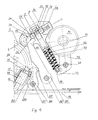
- FIG. 6 shows a preferred embodiment of the belt tensioner, in which the tension spring can be arranged at a more distant point in the vehicle and the force of which is transmitted to the belt tensioning mechanism, for example via a Bowden cable that can.
- This embodiment differs in that the force P of the tension spring is received in the rest position by a hook arm 83 of a lever 82 which is rotatably mounted about an axis 37 'on the base plate 2 in the vicinity of the locking mechanism 14 and by means of a tooth 84 an abutment element 85 executed on the circumference of the locking mechanism 14, preferably on the circumference of the toothed disk 5, cooperates.
- This abutment element 85 can be designed as a rod, as a projection or as a tooth.
- the feeler arm 80 of the closing lever 81 of the lever system has a rectangular cutout 34 similar to the feeler arm 32 of the closing lever 31.
- a sliding surface is embodied on the rear of the arm 80, which cooperates with a cam 87 on the rear of the hook arm 83 (FIG . 9).
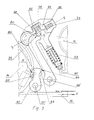
- FIG. 8 shows another design of the plunger of the trigger mechanism in the manner of the representation of FIG. 3.
- the plunger 46 ' is a U-shaped bracket which has two opposite rectangular openings 89 at the ends of its legs 88 in FIG which the locking member 45 'is inserted in the form of a rectangular short rod.
- the locking member 45 is fixed after it is inserted into said openings by means of a limiting plate 90, which plate supports the rollers 40, 41 from above and holds them in the intended position. This training is less prone to manufacturing errors and inaccuracies.
- the belt tensioner described can be attached to the frame or the seat of the vehicle by means of an attachment hole 61. Another possibility is to fasten the bolt axis 3 of the rope sheave 4, which is also suitable for this purpose, to the frame or to the seat.
- the deflection of the mass carrier 58 and the displacement of the tappet 46 occurring at a given deceleration of the vehicle depends on the mass M, the force and the characteristic of the actuation spring 53 and the geometry of the kinematics. These are selected so that the delays that occur during normal driving operation cause the plunger to move by no more than 2 E2.
- This position is shown in Fig. 5 with solid lines; the starting position of the locking member 45 and the rollers 40, 41 is shown in dashed lines. It can be seen that in the event of vibrations within this range, the rollers 40, 41 remain supported between the surfaces A, 35 and B, 42 and hold the probe arm 32 in its rest position.
- the pressing force F of the pressure surface 35 on the roller 40 originating from the tension spring force P remains trimmed via the locking member and the roller 41 on the post 43.
- the actuating spring 53 brings the plunger 46 and the rollers back into their initial rest position with their force T, and the mass carrier 58 is also pivoted back into its initial position.
- the mass carrier 58 will pivot by a larger angle a (FIG. 4) and the displacement of the locking member 45 exceeds the size of 2 E2.
- the rollers 40, 41 lose their hold on the side surfaces A, B of the locking member 45 and the feeler arm 32 throws the roller 40, the contact of which is still in contact with the pressure surface 35, into the space below the locking member 45. This is done by rotating the Probe arm 32, through which the cam arm 30 releases the cam 29 of the first lever 27, so that it can also pivot counterclockwise and its tooth 28 releases the mounting sleeve 21.
- the tension spring 11 can expand and pulls the belt buckle 12 downward by the amount H via the traction cable 16, 15 while rotating the locking mechanism 14 in the counterclockwise direction, as a result of which the seat belt is tightened.
- the locking mechanism 14 made of toothed disc 5 and pawl 7 is dimensioned so that it withstands the tensile loads that occur.
- the mass carrier 58 swivels in the same way about the axis 59 and lifts the plunger 46 'with the locking member 45' by an amount greater than 2 E2, so that the rollers 40, 41 roll a greater distance than E2, so that the roller 40 is supported at the locking member 45 '.
- the closing lever 81 throws the roller 40 under the locking member 45 'and thereby allows the lever 82 to pivot clockwise, the cam 87 sliding on the back of the closing lever 81.
- the tooth 84 of the lever 82 releases the abutment element 85 so that the tension spring can retract the belt buckle by the amount H via the locking mechanism.
Landscapes
- Engineering & Computer Science (AREA)
- Mechanical Engineering (AREA)
- Automotive Seat Belt Assembly (AREA)
Priority Applications (3)
| Application Number | Priority Date | Filing Date | Title |
|---|---|---|---|
| DE59400299T DE59400299D1 (de) | 1994-02-24 | 1994-02-24 | Gurtstrammer für Sicherheitsgurte |
| EP19940102751 EP0669232B1 (fr) | 1994-02-24 | 1994-02-24 | Tendeur de ceinture de sécurité |
| RU95102144A RU2085419C1 (ru) | 1994-02-24 | 1995-02-13 | Устройство для натяжения ремней безопасности |
Applications Claiming Priority (1)
| Application Number | Priority Date | Filing Date | Title |
|---|---|---|---|
| EP19940102751 EP0669232B1 (fr) | 1994-02-24 | 1994-02-24 | Tendeur de ceinture de sécurité |
Publications (2)
| Publication Number | Publication Date |
|---|---|
| EP0669232A1 true EP0669232A1 (fr) | 1995-08-30 |
| EP0669232B1 EP0669232B1 (fr) | 1996-05-22 |
Family
ID=8215714
Family Applications (1)
| Application Number | Title | Priority Date | Filing Date |
|---|---|---|---|
| EP19940102751 Expired - Lifetime EP0669232B1 (fr) | 1994-02-24 | 1994-02-24 | Tendeur de ceinture de sécurité |
Country Status (3)
| Country | Link |
|---|---|
| EP (1) | EP0669232B1 (fr) |
| DE (1) | DE59400299D1 (fr) |
| RU (1) | RU2085419C1 (fr) |
Cited By (3)
| Publication number | Priority date | Publication date | Assignee | Title |
|---|---|---|---|---|
| DE19629263A1 (de) * | 1995-08-15 | 1997-02-20 | Rahvaettevote Norma Tallinn | Gurtstrammer für Sicherheitsgurte |
| US6214324B1 (en) | 1999-02-12 | 2001-04-10 | Societe L'oreal S.A. | Photoprotective/cosmetic compositions comprising benzotriazole and benzoazolyl/benzodiazolyl sunscreens |
| CN117419884A (zh) * | 2023-12-19 | 2024-01-19 | 贵州地矿基础工程有限公司 | 危岩体模拟崩塌试验装置 |
Citations (2)
| Publication number | Priority date | Publication date | Assignee | Title |
|---|---|---|---|---|
| DE3229304A1 (de) * | 1982-08-05 | 1984-02-16 | Repa Feinstanzwerk Gmbh, 7071 Alfdorf | Rueckstrammer fuer ein sicherheitsgurtsystem fuer kraftfahrzeuge |
| EP0305765A2 (fr) * | 1987-08-10 | 1989-03-08 | Autoliv-Kolb GmbH & Co. | Détecteur d'accélération pour systèmes de sécurité et/ou systèmes de ceintures de sécurité de voiture |
-
1994
- 1994-02-24 EP EP19940102751 patent/EP0669232B1/fr not_active Expired - Lifetime
- 1994-02-24 DE DE59400299T patent/DE59400299D1/de not_active Expired - Fee Related
-
1995
- 1995-02-13 RU RU95102144A patent/RU2085419C1/ru not_active IP Right Cessation
Patent Citations (2)
| Publication number | Priority date | Publication date | Assignee | Title |
|---|---|---|---|---|
| DE3229304A1 (de) * | 1982-08-05 | 1984-02-16 | Repa Feinstanzwerk Gmbh, 7071 Alfdorf | Rueckstrammer fuer ein sicherheitsgurtsystem fuer kraftfahrzeuge |
| EP0305765A2 (fr) * | 1987-08-10 | 1989-03-08 | Autoliv-Kolb GmbH & Co. | Détecteur d'accélération pour systèmes de sécurité et/ou systèmes de ceintures de sécurité de voiture |
Cited By (4)
| Publication number | Priority date | Publication date | Assignee | Title |
|---|---|---|---|---|
| DE19629263A1 (de) * | 1995-08-15 | 1997-02-20 | Rahvaettevote Norma Tallinn | Gurtstrammer für Sicherheitsgurte |
| US6214324B1 (en) | 1999-02-12 | 2001-04-10 | Societe L'oreal S.A. | Photoprotective/cosmetic compositions comprising benzotriazole and benzoazolyl/benzodiazolyl sunscreens |
| CN117419884A (zh) * | 2023-12-19 | 2024-01-19 | 贵州地矿基础工程有限公司 | 危岩体模拟崩塌试验装置 |
| CN117419884B (zh) * | 2023-12-19 | 2024-05-28 | 贵州地矿基础工程有限公司 | 危岩体模拟崩塌试验装置 |
Also Published As
| Publication number | Publication date |
|---|---|
| RU2085419C1 (ru) | 1997-07-27 |
| EP0669232B1 (fr) | 1996-05-22 |
| RU95102144A (ru) | 1996-11-20 |
| DE59400299D1 (de) | 1996-06-27 |
Similar Documents
| Publication | Publication Date | Title |
|---|---|---|
| DE10027134B4 (de) | Rückziehvorrichtung für einen Fahrzeugsicherheitsgurt | |
| DE3330938C2 (fr) | ||
| DE2734116C2 (de) | Aufroll-Hemmvorrichtung für einen Sicherheitsgurt | |
| DE2612126C3 (de) | Sicherheitsgurt-Einzieheinrichtung | |
| EP0307822A2 (fr) | Dispositif de blocage de sangle pour une ceinture de sécurité à enrouleur | |
| EP0769433A2 (fr) | Enrouleur de ceinture de sécurité avec tensionneur et limitation de tension | |
| EP1963146B1 (fr) | Enrouleur de ceinture de securite comportant un limitateur de force commande en fonction de l'extraction de la ceinture | |
| DE2722487A1 (de) | Einziehvorrichtung fuer sicherheitsgurte | |
| DE3933453A1 (de) | Gurtaufroller | |
| DE3417877A1 (de) | Sicherheitsgurtsystem | |
| DE3844130C2 (de) | Gurtstrammer für Fahrzeugsicherheitsgurte | |
| DE4311214C2 (de) | Gurtstraffer für Fahrzeugsicherheitsgurte | |
| EP0669232B1 (fr) | Tendeur de ceinture de sécurité | |
| DE19514090A1 (de) | Anschnallgurt-Wickelvorrichtung | |
| DE2824864A1 (de) | Gurtaufrollschnellsperrautomat | |
| DE2806600A1 (de) | Einziehvorrichtung fuer sicherheitsgurte mit zweifacher zugkraft | |
| DE3432451A1 (de) | Sicherheitsgurtanordnung | |
| DE3229304C2 (de) | Rückstrammer für ein Sicherheitsgurtsystem für Kraftfahrzeuge | |
| EP0498001B1 (fr) | Dispositif pré-tendeur dans un système de ceinture de sécurité pour véhicule automobile | |
| DE3804177C2 (fr) | ||
| DE2413087A1 (de) | Sicherheitsgurtaufroller mit doppelfunktion | |
| DE68902501T2 (de) | Sperrvorrichtung fuer sicherheitsgurtstrammer eines fahrzeuges. | |
| DE2308895A1 (de) | Fahrzeugsitz mit verstellbarer rueckenlehne | |
| DE3624569A1 (de) | Sicherheitsgurt-rueckhaltevorrichtung | |
| DE2745591A1 (de) | In notsituationen sperrende einziehvorrichtung fuer sicherheitsgurte mit verringerbarer gurtzugkraft |
Legal Events
| Date | Code | Title | Description |
|---|---|---|---|
| PUAI | Public reference made under article 153(3) epc to a published international application that has entered the european phase |
Free format text: ORIGINAL CODE: 0009012 |
|
| 17P | Request for examination filed |
Effective date: 19940830 |
|
| AK | Designated contracting states |
Kind code of ref document: A1 Designated state(s): DE FR GB IT NL SE |
|
| RBV | Designated contracting states (corrected) |
Designated state(s): DE FR GB IT NL SE |
|
| GRAH | Despatch of communication of intention to grant a patent |
Free format text: ORIGINAL CODE: EPIDOS IGRA |
|
| GRAA | (expected) grant |
Free format text: ORIGINAL CODE: 0009210 |
|
| AK | Designated contracting states |
Kind code of ref document: B1 Designated state(s): DE FR GB IT NL SE |
|
| PG25 | Lapsed in a contracting state [announced via postgrant information from national office to epo] |
Ref country code: NL Free format text: LAPSE BECAUSE OF FAILURE TO SUBMIT A TRANSLATION OF THE DESCRIPTION OR TO PAY THE FEE WITHIN THE PRESCRIBED TIME-LIMIT Effective date: 19960522 Ref country code: IT Free format text: LAPSE BECAUSE OF FAILURE TO SUBMIT A TRANSLATION OF THE DESCRIPTION OR TO PAY THE FEE WITHIN THE PRE;WARNING: LAPSES OF ITALIAN PATENTS WITH EFFECTIVE DATE BEFORE 2007 MAY HAVE OCCURRED AT ANY TIME BEFORE 2007. THE CORRECT EFFECTIVE DATE MAY BE DIFFERENT FROM THE ONE RECORDED.SCRIBED TIME-LIMIT Effective date: 19960522 Ref country code: FR Effective date: 19960522 |
|
| REF | Corresponds to: |
Ref document number: 59400299 Country of ref document: DE Date of ref document: 19960627 |
|
| GBT | Gb: translation of ep patent filed (gb section 77(6)(a)/1977) |
Effective date: 19960606 |
|
| PG25 | Lapsed in a contracting state [announced via postgrant information from national office to epo] |
Ref country code: SE Effective date: 19960822 |
|
| EN | Fr: translation not filed | ||
| EN | Fr: translation not filed | ||
| NLV1 | Nl: lapsed or annulled due to failure to fulfill the requirements of art. 29p and 29m of the patents act | ||
| PLBE | No opposition filed within time limit |
Free format text: ORIGINAL CODE: 0009261 |
|
| STAA | Information on the status of an ep patent application or granted ep patent |
Free format text: STATUS: NO OPPOSITION FILED WITHIN TIME LIMIT |
|
| 26N | No opposition filed | ||
| PGFP | Annual fee paid to national office [announced via postgrant information from national office to epo] |
Ref country code: DE Payment date: 19980122 Year of fee payment: 5 |
|
| PG25 | Lapsed in a contracting state [announced via postgrant information from national office to epo] |
Ref country code: GB Free format text: LAPSE BECAUSE OF NON-PAYMENT OF DUE FEES Effective date: 19980224 |
|
| GBPC | Gb: european patent ceased through non-payment of renewal fee |
Effective date: 19980224 |
|
| PG25 | Lapsed in a contracting state [announced via postgrant information from national office to epo] |
Ref country code: DE Free format text: LAPSE BECAUSE OF NON-PAYMENT OF DUE FEES Effective date: 19991201 |