EP0669552A2 - Vorrichtung zum Ordnen und Speichern von Transparanten - Google Patents
Vorrichtung zum Ordnen und Speichern von Transparanten Download PDFInfo
- Publication number
- EP0669552A2 EP0669552A2 EP95630002A EP95630002A EP0669552A2 EP 0669552 A2 EP0669552 A2 EP 0669552A2 EP 95630002 A EP95630002 A EP 95630002A EP 95630002 A EP95630002 A EP 95630002A EP 0669552 A2 EP0669552 A2 EP 0669552A2
- Authority
- EP
- European Patent Office
- Prior art keywords
- transparency
- tray
- region
- sheet
- platen
- Prior art date
- Legal status (The legal status is an assumption and is not a legal conclusion. Google has not performed a legal analysis and makes no representation as to the accuracy of the status listed.)
- Withdrawn
Links
Images


Classifications
-
- G—PHYSICS
- G03—PHOTOGRAPHY; CINEMATOGRAPHY; ANALOGOUS TECHNIQUES USING WAVES OTHER THAN OPTICAL WAVES; ELECTROGRAPHY; HOLOGRAPHY
- G03B—APPARATUS OR ARRANGEMENTS FOR TAKING PHOTOGRAPHS OR FOR PROJECTING OR VIEWING THEM; APPARATUS OR ARRANGEMENTS EMPLOYING ANALOGOUS TECHNIQUES USING WAVES OTHER THAN OPTICAL WAVES; ACCESSORIES THEREFOR
- G03B21/00—Projectors or projection-type viewers; Accessories therefor
- G03B21/132—Overhead projectors, i.e. capable of projecting hand-writing or drawing during action
Definitions
- This invention relates to transparency organizer and storage tray, which is particularly suitable; to store transparencies in a convenient and sequential order; and, to be used as a retrofit overlay on an overhead transparency film sheet projector to allow the user to simply slide transparencies from the tray onto the projecting surface or platen of the projector from which the transparency is viewed: and, thereafter, to slide the transparency back into the same storage tray for storage; were they are collated in the same original sequential order.
- an overhead projector which generally has an upper flat glass plate, acting as a translucent platen sized a little larger than 81 ⁇ 2 by 11 inches, or metric A4, onto which is placed a transparency film sheet which is to be projected by the projector onto a screen overhead.
- a source of light which passes through the platen, and the transparency film sheet, to reflect off and inclined mirror projecting the light with its latent transparency image onto the overhead screen for view by an assembly of people in a room such as in a conference room, meeting room, classroom, and the like.
- the organization of transparency film sheets for such presentation has been haphazard at best and normally requires a second table adjacent to that of the projector onto which the transparency film sheets are stacked prior to display, requiring individual, sequential transport onto the projector platen, and then removal onto a collection stack, normally also located on the second table.
- the transparency film sheet to be projected is first removed from the source pile and placed on the projector platen, and then after viewing, is removed from the projector platen to be put onto a collection or completion pile adjacent to the source transparency pile.
- the invention therefore contemplates a transparency organizer and storage tray (10) adapted to act as a sheet (T) holding, transferring, and repository means for managing the flow control of a plurality of transparency film sheets (T), each generally impressed with indicia creating a discernible image when viewed, characterized by a tranparency film sheet carrying region (13) including, a first transparency film sheet source holding region (14) adapted to house a plurality of sheets (T) which are to be projected, a second sub-adjacent transparency film sheet storage region (15) adapted to house a plurality of said sheets (T) after projection, means (M, 24, 31) for holding the transparency film sheet carrying region (13), at an elevation so that the bottom (19) of the second transparency film sheet storage region (15) is at an elevation generally co-incident with a platen element, actual or imaginary, (11,PP) of a transparency projector (P) so that light passes through that transparency film sheet (T) for viewing when light passes through the platen element and that transparency film sheet (T) overlaying the
- the tray (10) additionally includes a cover (C) and an anchoring means (47) carried by the tray (10), one end of the cover (C) being is articulatingly attached through a flexible hinge (12) to the margin of the second transparency film storage region (15), the cover (C) including a plurality of articulating elements and surfaces (12, 30 through 45), at least one of which (30, 39) being adapted to carry means (50, 55) for removable attachment of the tray (10) to a transparency projector (P), one panel (45) of the cover (C) carrying means (46) for removable attachment to the anchoring means (47) whereby the cover (C), in its closed position, overcovers and secures closed, the regions (14, 15); and, in an operative position exposes proximate margins of said regions (14, 15) at an operative elevation intersecting the prolongation of the axial plane of the platen (11,PP) whereby to permit slide transport of the transparency (T) into and out of the tray (10) out from the upper region (14),
- first and second transparency regions (14, 15) are imaginary sub-regions of the sheet carrying region (13); that an elevated ramp anchor bar (312) is mounted preferably across the forward margin of the bottom (20) at a distance which is narrower than the depth or width of the transparencies (T) and the means for holding the transparency film sheet carrying region (13) is a translucent laminate sheet attached to the elevated ramp anchor bar (312), with its upper sheet (111U) being a mylar and the lower sheet (111L), being a cling vinyl which is adapted to fold into and fold out of the tray, for storage or use as the case might be.
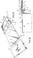
- a transparency organizer and storage tray (10) is shown in its open operative position as (10') and has a translucent sheet glass plate or sub-platen (11) hingeably attached through a flexible hinge (12) to the lower lateral distal margin (12') of a transparency holding region (13) of the tray (10); including, and most clearly seen in the cross-section Figure 3, an upper tray region (14) and a lower tray region (15) respectively separated by an inter-regional or lateral separation plate, or partition wall (16), but see Figure 14 where the plate (16) can be avoided.
- the upper tray region (14) acts as a holding source region for a plurality of transparency film sheets (T) and it has an overcovering sheet plate (17), which in Figure 4 is shown as translucent, with a marginal notch (18) adapted to accommodate the index finger of the operator for the purposes, as will be described, more fully hereafter, to move the topmost transparency (T) from region (14) onto the sub-platen (11) simply by "touch and push".
- the lower tray region (15) is separated, at its forward end, by a flexible sheet spring (19) as is most clearly seen in figures 1 through 5 and separates the lower tray region (15) into a sub-adjacent lower sub-region (15L) and a super-adjacent lower sub-region (15U).
- a flexible sheet spring (19) as is most clearly seen in figures 1 through 5 and separates the lower tray region (15) into a sub-adjacent lower sub-region (15L) and a super-adjacent lower sub-region (15U).
- the forward margin (19F) of the sheet spring (19) is recessed a small distance from the open proximate margin of the lower tray region (15L), of the dual tray portion (13).
- the hinge attachment (12) is flexed convex, when in the open position, and is most clearly seen in that configuration in figure 3.
- the hinge attachment (12) can be resilient material or a suitable form so that on its one lateral margin, it can be affixed, at 12', to the lower proximate margin of the bottom panel (20) which forms the bottom of the lower tray region (15).
- the bottom panel (20) acts as the bottom of the dual tray portion (13).
- the lateral depth of the lower tray (15) can be such that there can be an internal end wall (21), which thereby defines a rectangular laterally oriented plenum (22) along the back margin of the tray (10) into which, can be placed cylindrical articles, seen in figure 5 and noted as (23), being markers, pointers and the like. They can be removed if a sliding side door or panel (24) is provided, seen, unclearly, in the embodiment of figure 5, prior to placing the tray (10) in the open operative position.
- the tray (10) in order to counter-lever the mis-distribution of weight, when in the open operative position of figures 1, 2 and 3, the tray (10) is provided with lateral legs (24) which are pivotly hinged by a wing nut means (25) to the distal end of the dual tray portion (13) so as to allow the movement of the legs into depending position in the open operative position of figure 1; and alternatively, or as seen in the top plan view and perspective views, figures 2 and 4 respectively into the closed collapsed position so as to be juxtaposed to the ends of the dual tray portion (13). It is preferred, in the embodiment of figures 1 through 4, that these legs (24) have an obround race or aperture (26), which is shown in figures 1 and 4 but not in the other figures.
- the tray (10) to be positioned at an elevational suitable to that of the projector (P), depending upon the projector height (H).
- Some projectors (P) have a deep height (H), for instance, those in which the illuminating source is within the projector (P), while others have a thin height (H) as where the illuminating source is adjacent the reflective mirror (R) and shines down onto the platen (PP) of the projector (P) through the transparency (T) and then back up onto the mirror for reflection forward onto a screen.
- the projector platen (PP) is a reflective Frenel lense.
- the obround aperture (26) is preferred to be defined in the legs (24) for the accommodation of different projector heights (H).
- Such legs (24) can be avoided by the embodiment shown in figure 5. In this embodiment, the legs (24) are non-existent.
- a sheet of flexible sheet of magnetic material (M) has its marginal edge affixed through a second flexible hinge (FH) attached to the distal edge of the sub-platen (11).
- the projector body (P) is made of metal and the magnetic sheet (M), when placed near the projector body (P) fixedly attaches itself, in a removable manner of course, to secure the holder (10) to the projector (P).
- the sub-platen (11) is imaginary and is defacto substituted, to be the existing projector platen (PP), or reflective Frenel lense, of the projector (P).
- the flexible hinge (12) has, on its distal margin, a lateral strip (30), the lower surface (31) of which is either an adhesive or a strip of Velcro®.
- the strip (30) is press fitted onto the lateral edge of platen (PP), actually to the marginal top of the projector (P), see Figure 6 by appropriate means to hold the lower sub-region (15) in a plane that intersects the plane of a platen (PP).
- the sheet spring (19) is in fact a cut sheet of transparency sheet material whose forward margin (19F, 35) has its underside covered with an adhesive (36) which sticks to the upper surface of a bottom cardboard panel (20).
- An underlying strip (37) of open-cell foam which acts as a biasing means on the flexible sheet spring (19) is located away from the margin (19F,35) yet under the sheet spring (19)and is adhesively secured, preferably to the upper surface of the bottom panel (20) rather than to the under surface of the sheet spring (19).
- the forward margin (19F) of the flexible hinge (19) is at an elevation at, or preferably marginally below the sub-platen (PP) or imaginary sub-platen (PP'), see the cross-section Figure 3.
- the uppermost transparency (T) in the upper region (14) is touched with the human index finger extending into the slot (18) and moved laterally in the direction of the arrow (A) in Figure 3, the uppermost transparency (T) is slipped onto the platen (P), shown in phantom in that figure as (T V ) and referred to as transparency being viewed.
- the forward face (19F) of the hinge being recessed away, distance (D) in Figure 3, from the proximate open faces of regions (14) and (15) allow that transparency (T S ), when seated in the super-adjacent lower sub-region (15U), to "overhang" the forward face (19F) of the hinge (19) so that when the next transparency on the platens (11,PP) is moved in the direction (B) from the platens (11,PP), that transparency (T S 2), indexes underneath the first transparency (T S ) yet enters the super-adjacent lower sub-region (15U).
- the transparencies are organized and stacked in the super-adjacent lower sub-region (15U) in the identical viewing sequence, as they had existed in the upper tray region (14).
- the group of the transparencies located in the super-adjacent lower sub-region (15U) maybe collectively pulled out of that sub-region (15U) and placed into the upper region (14). Sequential viewing can then simplistically take place repeating the above steps.
- the sub-adjacent lower subregion (15L) acts as a plenum reservoir to the super-adjacent lower sub-region (15U).
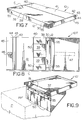
- the transparency organizer and storage tray (10) is shown in its closed position in Figure 7; in its transitional fully flat open position, as (10T) in Figure 8, and in the assembled operative position, adhering to a transparency projector (P), as (10') in Figure 9.
- This tray (10, 10T, 10') is preferably made of cardboard and the flexible hinge (12) of Figure 6 is now referenced the same as in Figure 6, but in Figures 7 and 8 now also acts as the lowest most hinge interconnecting through to the front lateral strip (30) both being integral elements of an integral cover-tray support structure (C), comprising integral articulating elements, (12, 30) through 45).
- the cover sheet (C) closes the tray (10) to contain any transparencies (T) located in either of the upper tray region (14) or in the lower tray region (15), yet each of the regions (14, 15) is still respectively separated by the partition wall (16), the lower tray region (15) also having the sheet spring (19) sub-partitioning the lower tray region (15) into its sub-adjacent lower sub-region (15L) and the super adjacent lower sub-region (15U).
- the cover (C) is thus a plurality of sheet elements (12, 30 through 45), and includes the hinge (12) as the lower margin of the front lateral strip (30) which, as its upper margin, is a fold mark (38), and margin to a flat upper forward sheet (39), the opposite side of which is a top lateral fold mark (40) integral to an upper rear flat sheet (41); an upper rear corner fold mark (42) that in fact is the upper rear corner of the tray (10) when in the closed storage position of Figure 7.
- This Velcro® strip (47) is rectangular and long; centered with its longitudinal axis oriented in the lateral direction, as shown in phantom in Figure 8, so that the other rectangular Velcro® strip (46) can, when in the closed position, as in the Figure 7, mate with a portion of the Velcro® strip (47) and, when to be in one of the open assembled positions of Figure 9 and subsequent, can be released, located and re-attached to the same Veclro® strip (47) thus, respectively holding the tray, either in the closed storage position of Figure 7 or in one of the open operative positions of Figures 7 through 11.
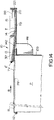
- FIG 8 on the inner surface of the upper panel (39) are affixed three rectangularly shaped flexible composite magnetic flat strips (50) that extend between fold marks (38 and 40). They are depicted again in Figure 9 and provide means for magnetic adhesion of the tray (10) to a magnetizable metallic side of the projector body (P), holding the tray (10), generally parallel to and at an elevation, relative the platen (PP), so that the plane of the platen (PP) intersects the lower tray region (15), particularly sub-adjacent lower sub-region (15L).
- the panel (30) is also provided with at least two obround apertures (55), more clearly seen in Figures 7, 8, 9 and elevtional cross-sectional Figure 11.
- a suction cup (60) can be pressed fit since the cup (60) normally has an integral stem with bulbous distal end (65).
- the tray (10') when in its open operative position, as shown in Figure 11 can be suitably secured to the side of a projector (P) whose body is not composed of a magnetized material such as steel or the like, but of a non-metallic material, aluminum, plastic or other composite.
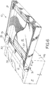
- the tray (10) is shown in solid form of Figure 12 in its attitude after an overcovering sleeve (S), common to both of these two embodiments is slid off the operative elements of the tray (10).
- the operative elements consist of transparency holding region (13) that in Figures 12 and 13 includes the upper transparency holding region (14) upon which transparencies to be projected are placed, which overlays the lower transparency holding tray region (15), adapted to hold transparencies after viewing; the two regions (14) and (15) separated by inter-regional separation plate or partition wall (16); in Figure 14 the inter-regional plate (16) is not required, for reasons to be explained.
- the hinge (12) acts as the hinge point for a support flap (139) which, in Figure 12, is shown folded and underlaying bottom sheet panel (20) of the tray (10) which is its storage position.
- an elevated ramp anchor bar (312) Surmounting the hinge (12) and to the rear thereof is an elevated ramp anchor bar (312), which also acts as anchor means for a flexible clear plastic laminate film sheet (111) laminated from two sheets (111U, 111L).
- the upper sheet (111U) is preferably a clear Mylar® film, while the bottom sheet (111L) is a static cling vinyl film: thus, the upper surface (111U) provides a smooth sliding surface over which transparencies can slide to and from while the lower surface (111L) is tactile and is adapted to overlay the platen (PP) of the projector (P) and adhere to it as by pressing it onto the platen (P) by running one's hand over the upper surface (111U) so that the under tactile surface (111L) of the sheet (111) adheres to the platen (PP).
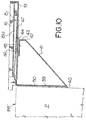
- the clear plastic film laminate sheet (111) is sized so that its distal margin extends into a document cover slide clamp (112), which acts as a rigid frame for the distal end and also partially as a weight, in the operative and use position, as in Figure 13, to additionally support the tray (10) on the platen.
- a document cover slide clamp (112) acts as a rigid frame for the distal end and also partially as a weight, in the operative and use position, as in Figure 13, to additionally support the tray (10) on the platen.
- the support flap (139) has a push-out support tab (141), which is pushed out from the body of the flap (139).
- the tab (141) has an upper finger (142) integral therewith that nests into a longitudinal notch (120) in the bottom (20).
- the finger (142) indexes into the notch (120) and stabilizes the flap (139) in the vertical position so that it can be placed in juxtaposition with the side of the projector (P).
- the clear plastic film sheet (111) can then be press fit over the platen, as earlier described, and the tray (10') is now in its operative positions of Figures 13 or 14.
- the laminate sheet (111) extends over the top of the elevated ramp anchor bar down the backside thereof and along the upper surface of the bottom (20) as shown in figures 13 and 14.
- Careful review of the cross-sectional figure 13 shows that the lower region (15) is “shorter” in length than the upper region (14) because the lower region (15) has the inner rear wall (21) which keeps the leading edges of the "viewed" transparencies overhanging the elevated ramp anchor bar (312).
- the height of the elevated ramp anchor bar (312) be exaggerated by multiplying several layers of light cardboard stock as a spacer so that the anchor bar (312) is now thick, say having a height of 1/4'' (.6cm), above the upper surface of the bottom (20).
- the laminate sheet (111) overcovers the top of the anchor bar (312) to provide a glide path or ramp over which viewed transparencies (T V ) can be slid so as to successively index under the leading edge (E) of the lowest of the bottom viewed slide group (t B ) and to be stored there.
- tray (10) depth from hinge (12) to the back wall (ooo) of the tray is less the width of a transparency (T) and all transparencies are flush with the forward margin of the ramp anchor bar (312) or putting it another way essentially flush with the hinge (12).
- a tray (10) for use with transparencies sized to U.S.A. letter standard, also known as imperial (8 1/2'' x 11'') will be slightly wider than those sized A4 metric.
- Figure 4 shows a rear rail (RR).
- the transparencies (T) are stored under this tray but when the tray is to be stored and put into its sleeve (F), the laminate sheet (111) can be folded and placed on top of this rear rail (RR) so that it does not crease since the cling vinyl surface has a tendency to crease, if under pressure. If this happens when the transparencies are viewed, there is a black line through the transparency because of the crease in the laminate sheet (111).
- the balance of the tray (10) is of thin wall corrugated cardboard, approximately 1.5mm thick (1/16th of an inch).
Landscapes
- Physics & Mathematics (AREA)
- General Physics & Mathematics (AREA)
- Overhead Projectors And Projection Screens (AREA)
- Sheets, Magazines, And Separation Thereof (AREA)
- Packaging For Recording Disks (AREA)
Applications Claiming Priority (4)
| Application Number | Priority Date | Filing Date | Title |
|---|---|---|---|
| CA2114390 | 1994-01-26 | ||
| CA002114390A CA2114390A1 (en) | 1993-04-16 | 1994-01-26 | Transparency organizer and storage tray |
| CA2116523 | 1994-02-18 | ||
| CA002116523A CA2116523A1 (en) | 1993-04-16 | 1994-02-18 | Transparency organizer and storage tray |
Publications (2)
| Publication Number | Publication Date |
|---|---|
| EP0669552A2 true EP0669552A2 (de) | 1995-08-30 |
| EP0669552A3 EP0669552A3 (de) | 1995-12-13 |
Family
ID=4152808
Family Applications (2)
| Application Number | Title | Priority Date | Filing Date |
|---|---|---|---|
| EP93909731A Withdrawn EP0646255A1 (de) | 1993-04-16 | 1993-05-14 | Vorrichtung zum ordnen und speichern von transparenten |
| EP95630002A Withdrawn EP0669552A3 (de) | 1994-01-26 | 1995-01-19 | Vorrichtung zum Ordnen und Speichern von Transparanten. |
Family Applications Before (1)
| Application Number | Title | Priority Date | Filing Date |
|---|---|---|---|
| EP93909731A Withdrawn EP0646255A1 (de) | 1993-04-16 | 1993-05-14 | Vorrichtung zum ordnen und speichern von transparenten |
Country Status (5)
| Country | Link |
|---|---|
| EP (2) | EP0646255A1 (de) |
| JP (2) | JPH07508108A (de) |
| AU (1) | AU4057393A (de) |
| CA (2) | CA2114390A1 (de) |
| WO (1) | WO1994024605A1 (de) |
Families Citing this family (1)
| Publication number | Priority date | Publication date | Assignee | Title |
|---|---|---|---|---|
| CN112137350B (zh) * | 2020-09-16 | 2022-07-26 | 广州共生形态工程设计有限公司 | 一种建筑用房屋结构模型展示装置 |
Family Cites Families (6)
| Publication number | Priority date | Publication date | Assignee | Title |
|---|---|---|---|---|
| US3544211A (en) * | 1968-04-22 | 1970-12-01 | Panel Corp Q | Auxiliary stage for a visual projector |
| US3600079A (en) * | 1969-05-19 | 1971-08-17 | Milton Bradley Co | Transparency holder and viewing device |
| CA1125066A (en) * | 1979-09-11 | 1982-06-08 | John S. Wright | Extension platform to support transparencies for an overhead projector |
| US4632529A (en) * | 1984-03-16 | 1986-12-30 | Wilfred Levin | Accessory for use with an overhead projector |
| FR2656433B1 (fr) * | 1989-12-22 | 1992-05-07 | Genieis Jean | Dispositifs pour alimenter automatiquement un projecteur d'images. |
| US5198846A (en) * | 1992-06-23 | 1993-03-30 | Zilber Steven A | Manual cassette system for overhead projection transparencies |
-
1993
- 1993-05-14 AU AU40573/93A patent/AU4057393A/en not_active Abandoned
- 1993-05-14 EP EP93909731A patent/EP0646255A1/de not_active Withdrawn
- 1993-05-14 WO PCT/CA1993/000217 patent/WO1994024605A1/en not_active Ceased
- 1993-05-14 JP JP6522567A patent/JPH07508108A/ja active Pending
-
1994
- 1994-01-26 CA CA002114390A patent/CA2114390A1/en not_active Abandoned
- 1994-02-18 CA CA002116523A patent/CA2116523A1/en not_active Abandoned
-
1995
- 1995-01-19 EP EP95630002A patent/EP0669552A3/de not_active Withdrawn
- 1995-01-26 JP JP7010548A patent/JPH07219044A/ja active Pending
Also Published As
| Publication number | Publication date |
|---|---|
| CA2114390A1 (en) | 1994-10-17 |
| CA2116523A1 (en) | 1994-10-17 |
| WO1994024605A1 (en) | 1994-10-27 |
| EP0669552A3 (de) | 1995-12-13 |
| EP0646255A1 (de) | 1995-04-05 |
| JPH07219044A (ja) | 1995-08-18 |
| AU4057393A (en) | 1994-11-08 |
| JPH07508108A (ja) | 1995-09-07 |
Similar Documents
| Publication | Publication Date | Title |
|---|---|---|
| US4002355A (en) | Book with sound track and visual display | |
| US6270049B1 (en) | Tabletop easel with page retention | |
| EP0047306B2 (de) | Transparententasche für schreibprojektoren und ähnliche projektionsgeräte | |
| NZ229486A (en) | Cover for transparencies: mask flap welded on | |
| US4981386A (en) | Notebook with internal easel stand | |
| US3537792A (en) | Transparency projection system | |
| US6575758B1 (en) | Display holder and method for using same | |
| US4932529A (en) | Display and storage container with a liner having a spacer flap for photographic prints | |
| US5007192A (en) | Lapboard | |
| EP0669552A2 (de) | Vorrichtung zum Ordnen und Speichern von Transparanten | |
| JPH06336277A (ja) | 収納容器 | |
| US7051463B2 (en) | Document display and retention device | |
| US5475453A (en) | Manually-operated tray assembly for dispensing and receiving overhead projector transparencies | |
| US6659336B2 (en) | Horizontal container for the handling of flat objects | |
| JPH0719820Y2 (ja) | フォルダシステム | |
| US4108307A (en) | Storage binder | |
| US4068949A (en) | Document handling device | |
| US4110624A (en) | X-ray film holder or cassette | |
| CA1275191C (en) | Transparency presentation device | |
| CA2187492A1 (en) | Holder for transparencies | |
| US5100039A (en) | Curled document management device | |
| JP3031547U (ja) | オーバーヘッドプロジェクタ用支持シート | |
| US5584553A (en) | Reusable presentation frame for overhead transparencies | |
| US4467542A (en) | Chart sequencing device | |
| EP0221069A1 (de) | Vorrichtung zur informationspräsentation auf einer vielzahl seitenförmiger informationsträger |
Legal Events
| Date | Code | Title | Description |
|---|---|---|---|
| PUAI | Public reference made under article 153(3) epc to a published international application that has entered the european phase |
Free format text: ORIGINAL CODE: 0009012 |
|
| AK | Designated contracting states |
Kind code of ref document: A2 Designated state(s): DE FR GB |
|
| PUAL | Search report despatched |
Free format text: ORIGINAL CODE: 0009013 |
|
| AK | Designated contracting states |
Kind code of ref document: A3 Designated state(s): DE FR GB |
|
| STAA | Information on the status of an ep patent application or granted ep patent |
Free format text: STATUS: THE APPLICATION IS DEEMED TO BE WITHDRAWN |
|
| 18D | Application deemed to be withdrawn |
Effective date: 19960614 |