EP0669615A2 - Plattenbehälter - Google Patents
Plattenbehälter Download PDFInfo
- Publication number
- EP0669615A2 EP0669615A2 EP95102839A EP95102839A EP0669615A2 EP 0669615 A2 EP0669615 A2 EP 0669615A2 EP 95102839 A EP95102839 A EP 95102839A EP 95102839 A EP95102839 A EP 95102839A EP 0669615 A2 EP0669615 A2 EP 0669615A2
- Authority
- EP
- European Patent Office
- Prior art keywords
- main body
- case main
- disc
- case
- engagement pieces
- Prior art date
- Legal status (The legal status is an assumption and is not a legal conclusion. Google has not performed a legal analysis and makes no representation as to the accuracy of the status listed.)
- Withdrawn
Links
Images




Classifications
-
- G—PHYSICS
- G11—INFORMATION STORAGE
- G11B—INFORMATION STORAGE BASED ON RELATIVE MOVEMENT BETWEEN RECORD CARRIER AND TRANSDUCER
- G11B23/00—Record carriers not specific to the method of recording or reproducing; Accessories, e.g. containers, specially adapted for co-operation with the recording or reproducing apparatus ; Intermediate mediums; Apparatus or processes specially adapted for their manufacture
- G11B23/02—Containers; Storing means both adapted to cooperate with the recording or reproducing means
- G11B23/03—Containers for flat record carriers
- G11B23/032—Containers for flat record carriers for rigid discs
Definitions
- This invention relates to a disc case in which a data recording disc capable of reading and writing of magnetic data or optical data can removably be housed, more particularly to a disc case which can optionally be employed in a data processing unit such as a computer etc. in accordance with the specifications of the disc drive section thereof, allowing (1) loading of the disc as a simple to the disc drive section and (2) loading of the disc as housed in the disc case to the disc drive section.
- Data processing units including computers and word processors are classified into those which carry out reading and writing of magnetic data and those which carry out reading and writing of optical data, and discs (diskettes) are suitably employed as the data recording media for such units.
- discs diskettes
- floppy discs which are of soft sheet-like recording media housed in protecting jackets
- hard discs optical memory discs
- the optical memory discs are rather preferably employed because of their large capacities and low costs.
- the system of loading the latter hard disc into the disc drive section of the data processing unit includes (1) the tray system, in which the bare disc as a simple is as such loaded; and (2) the caddie system, in which the disc is preliminarily housed in a case main body and loaded together with the case main body.
- the case main body having the disc housed therein is as such loaded, the data recording surface of the disc is allowed to be exposed through the opening defined in the case main body, enabling reading and writing of data by the head of the disc drive section.
- the disc in which the disc as a simple is loaded as such, the disc is designed to be housed in a simple transparent plastic case for the protection and management thereof during storage.
- a user of the caddie system data processing unit in which the case main body is employed for loading the disc, wants to use the disc sold as a simple, he must put the disc in a predetermined case main body (adapter case) so as to establish interchangeability, under the present circumstances.
- Fig. 11 explains the mechanism of interchangeability established between a data processing unit PU1 (tray system) in which a hard disc 50 as a simple is loaded and a data processing unit PU2 (caddie system) in which an adapter case 52 having the disc 50 housed therein is loaded.
- the disc 50 as a simple can be loaded to one data processing unit PU1 but not as such to the other data processing unit PU2 due to the difference in the formats.
- the resulting adapter case 52 is loaded into the data processing unit PU2.
- the outer dimensions of the adapter case 52 is, of course, formatted such that it can be loaded to and unloaded from the disc drive section of the data processing unit UP2.
- An opening 52a is defined at the bottom of the adapter case 52, and the data recording surface of the disc 50 is designed to be exposed through this opening 52a.
- a shutter 43 which can close the opening 52a is slidably disposed to the adapter case 52, as shown in Fig. 12, so as to prevent invasion of dust and inadvertent touch of the fingers or hands of operators.
- the shutter 43 is automatically opened when the adapter case 52 is loaded into the data processing unit PU2 to allow the read/write head provided in the disc drive section to face the data recording surface of the disc 50, while it is closed automatically upon ejection of the adapter case 52.
- this mechanism generally consists of a number of parts and is assembled through many steps, leading to increased production cost of the entire adapter case 52, disadvantageously.
- this invention is proposed in order to solve the above problems, and it is an objective of the invention to provide a disc case characterized in that it can allow both loading of the disc as housed in the case main body to the disc drive section and loading of the disc separated from the case as a simple to the disc drive section, that it is produced with the reduced number of parts and reduced number of assembly steps so as to achieve cost reduction and enjoys extended life and high reliability, and that the opening and closing handleability of the cover is highly facilitated.
- the disc case according to this invention comprises a rectangular case main body, having a full-face opening defined at the top through which a data recording disc can removably be housed, and another opening defined at the bottom through which the data recording surface of the disc can radially be exposed; a cover plate, pivotally supported on one end portion of the case main body by hinge members, which can close the full-face opening of the case main body; a couple of first engagement pieces, provided on the rear surface of the cover plate at the other end portion opposite to the hinged portion to be extended toward the case main body; a couple of second engagement pieces, provided in the case main body at the positions corresponding to the locations of the first engagement pieces when the cover plate is closed, which resiliently engage with the first engagement pieces to lock the cover plate as closed with respect to the case main body; a protect case having a full-face opening through which the case main body can removably be fitted; and a couple of resiliently shiftable portions formed on each lateral side wall of the protect
- Fig. 1 is a schematic perspective view of the entire constitution of the disc case 1 according to the embodiment of the invention
- Fig. 2 shows perspectively the rear side of the case main body 2 with the cover 10 being open.
- the disc case 1 of the embodiment essentially consists of a rectangular case main body 2 in which a disc 50 can removably be housed, a cover plate 10 which can freely open and close the full-face opening of the case main body 2 and a protect case 20 in which the case main body 2 can removably be fitted.
- the case main body 2 has a full face opening through which the disc 50 can removably be housed, and it also has an opening 3, through which the data recording surface of the disc 50 can be exposed radially, defined at the bottom 2a.
- One end portion of the cover plate 10 and that of the case main body 2 are pivotally supported by a couple of hinge members 4 so that the full-face opening of the case main body 2 may freely be closed therewith.
- the protect case 20 is of a thin container which is slightly greater than the case main body 2 and also has a full-face opening through which the case main body 2 can removably be fitted.
- a couple of first engagement pieces 12 are provided on the rear surface of the cover plate 10 with a predetermined span therebetween at the other end portion (opposite to that end portion which is pivotally supported by the hinge members 4), and these first engagement pieces 12 protrude toward the case main body 2.
- a couple of second engagement pieces 11 are provided in the case main body 2 at the positions corresponding to the locations of the first engagement pieces 12 when the cover plate 10 is closed.
- the first engagement pieces 12 resiliently engage with the second engagement pieces 11 to lock the cover plate 10 closed (see Fig. 3)
- each first engagement piece 12 has a hooked engagement portion 12a formed integrally therewith as shown in Figs. 1 and 3.
- each second engagement piece 11 is provided as a part of the structure shown in the enlarged view of Fig.
- a couple of protrusions 5 are formed at the bottom 2a of the case main body 2 at the positions adjacent to the inner corners, respectively, with two urging pieces 7 each having a U-shape as a whole being separately provided on the case main body 2.
- each urging piece 7 is attached to the case main body 2 by engaging the slot defined at one foot 7a of the U-shape with the corresponding protrusion 5.
- the other foot 7b of the U-shaped urging piece 7 has a rectangle-columnar shape, and the second engagement piece 11 is integrally formed on the inner surface of the rectangular through hole 16 defined in the rectangle-columnar foot 7b.
- the second engagement pieces 11 also have hooked engagement portions 11 a respectively at the positions such that they can be engaged with the hooked engagement portions 12a of the corresponding engagement pieces 12, when the cover plate 10 is closed with respect to the case main body 2.
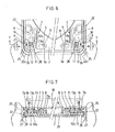
- the main body of each urging piece 7 has a U-shape, and thus the hooked engagement portion 11 a of the second engagement piece 11 and the hooked engagement portion 12a of the first engagement piece 12 are designed to have dimensions such that the former can normally be engaged with the latter, and that the engagement between these hooked engagement portions 11 a and 12a may be released when the urging piece 7 is pushed to be flexed in the direction indicated by the arrow in Fig. 6 (as will be described later) . Further, the reference number 6 indicated in Figs.
- notches 9 having a predetermined size are defined in the lateral side walls of the case main body 2 at the positions adjacent to the corresponding rectangle-columnar feet 7b. These notches 9 allow intrusion of protrusions 27 (to be descried later) provided on the inner surfaces of the lateral side walls of the protect case 20.
- the protect case 20 has four side walls 21,22,23 rising from its rectangular bottom 24, as shown in Fig. 1.
- the side wall 21 corresponding to the one standing from the rear part in Fig. 1 has a hood 21 a extending from the upper edge thereof horizontally inward, which serves as the guide when the case main body 2 is fitted into the protect case 20 and also as a stopper, as will be described later referring to Fig. 10.
- the side wall 23 standing from the front side of the rectangular bottom 24 is slightly notched downward at the middle, and a horizontally knurled non-slip member 23a is formed therein.
- slits 28 are defined at the bottom 24 to extend from the front side with a predetermined length toward the depth of the protect case 20 whereby to allow the non-slip members 22a to flex toward the inside of the protect case 20 and function as resiliently shiftable portions 25.
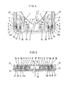
- a horizontal protrusion 27 is provided at the inner surface of each resiliently shiftable portion 25, which protrusion 27 is inserted to the notch 9 provided at the corresponding position of the case main body 2, when the case main body 2 is fully fitted in the protect case 20, to locate at the proximities of the corresponding second engagement pieces 11 formed on the U-shaped urging pieces 7, respectively, as shown in Figs. 3 to 5.
- the hooked engagement portions 11 a of the second engagement pieces 11 engage with the hooked engagement portions 12a of the corresponding first engagement pieces 11 to lock the cover plate 10 with respect to the case main body 2, as shown in Fig. 5.
- the right and left resiliently shiftable portions 25 are pushed with fingers inward, these portions 25 flex inward to allow the protrusions 27 to urge the rectangle-columnar feet 7b of the urging pieces 7. Accordingly, due to the yielding of the urging pieces 7 to the urging force of the protrusions 27, the hooked engagement portions 11 a are retracted from the hooked engagement portions 12a to release engagement therebetween, as shown in Fig.
- an oval opening 30 is defined at the bottom 24 of the protect case 20 at a position near the front end middle portion. This opening 30 is utilized for lifting the case main body 2 by inserting a finger of the user therethrough, when the case main body 2 is to be separated from the protect case 20.
- a holder 32 having a cylindrical form as a whole is formed at the center of the bottom 24 of the protect case 20.
- the holder 32 has a multiplicity of radial slits to form a plurality of engagement pieces 32a which can undergo resilient deformation in the radial direction.
- This holder 32 is resiliently fitted in the central opening of the disc 50 housed in the case main body 2 as fitted in the protect case 20 to hold the disc 50 stably thereby.
- the upper surface of the holder 32 is pushed with finger, and thus the engagement pieces 32a undergo resilient deformation radially inward to allow easy picking up of the disc 50.
- a hub 14 for chucking the disc 50 is provided at the substantially central position (corresponding to the center of the disc 50 housed therein) of the cover plate 10.
- a transparent rectangular plate 15 having a predetermined dimensions is removably fitted on the upper surface of the cover plate 10, as shown in Fig. 2, so that a label on which the title and other data can be written may be inserted between the transparent plate 15 and the upper surface of the cover plate 10.
- the transparent plate 15 is adapted to be removable only when the cover plate 10 is open with respect to the case main body 2, and not when the cover plate 10 is closed, since the cover plate 10, when closed, is designed to be abutted against the front edge of the case main body 2.
- Fig. 8 shows a state where the case main body 2 is fitted in the protect case 20, provided that a disc 50 is preliminarily housed in the case main body 2.
- the right and left resiliently shiftable portions 25 of the protect case 20 are pushed inward with fingers, as shown in Fig. 6.
- the resiliently shiftable portions 25 flex inward to let the U-shaped portions of the urging pieces 7 flex by the protrusions 27, whereby the engagement between the hooked engagement portions 12a and the hooked engagement portions 11 a is released (see Fig. 7). Accordingly, as shown in Fig.
- the cover plate 10 can be let open with respect to the case main body 2 to enable picking up of the disc 50 therefrom.
- the disc 50 can easily be picked up from the case main body 2 as the latter is fitted in the protect case 20.
- the disc 50 picked out of the disc case 1 can be used in the data processing unit PU 1 of the format which allows loading of the disc as a simple, as described referring to Fig. 11.
- the case main body 2 is to be separated from the protect case 20, it can be separated by simple procedures: the user puts one of his fingers in the opening 30 defined at the bottom 24 of the protect case 20 to push up the case main body 2, as shown in Fig. 10.
- the case main body 2 thus separated can be used in the data processing unit PU2 of the format which allows loading of the case main body 2, as described referring to Fig. 11, with the hooked engagement portions 11 a of the second engagement pieces 11 engaging with the hooked engagement portions 12a of the first engagement pieces 12 to unopenably lock the cover plate 10 with respect to the case main body 2.
- the disc 50 when the disc 50 is to be housed into the case main body 2, the disc 50 is set in position in the case main body 2 with the cover plate 10 being let open, as shown in Fig. 9.
- the cover plate 10 When the cover plate 10 is closed with respect to the case main body 2, the first engagement pieces 12 provided on the rear surface of the cover plate 10 are inserted to the corresponding rectangular through holes 16 of the urging pieces 7 provided on the case main body 2. Then, the hooked engagement portions 11 a of the second engagement pieces 11 provided on the inner surfaces of the rectangular through holes 16 resiliently engage with the hooked engagement portions 12a of the first engagement pieces 12 to unopenably lock the cover plate 10 with respect to the case main body 2.
- the procedures described referring to Fig. 10 may be repeated reversely. Namely, after the rear end portion of the case main body 2 is slipped immediately under the hood 21 a extended from the upper edge of the side wall 21 of the protect case 20, the upper surface of the case main body 2 is pushed downward to allow the notches defined on the lateral side walls of the case main body 2 to catch the protrusions 27 provided on the inner surfaces of the lateral side walls of the protect case 20. Thus, the case main body 2 can securely be fitted in the protect case 20.
Landscapes
- Packaging For Recording Disks (AREA)
Applications Claiming Priority (2)
| Application Number | Priority Date | Filing Date | Title |
|---|---|---|---|
| JP6055242A JPH07244951A (ja) | 1994-02-28 | 1994-02-28 | ディスクケース |
| JP55242/94 | 1994-02-28 |
Publications (2)
| Publication Number | Publication Date |
|---|---|
| EP0669615A2 true EP0669615A2 (de) | 1995-08-30 |
| EP0669615A3 EP0669615A3 (de) | 1996-01-24 |
Family
ID=12993134
Family Applications (1)
| Application Number | Title | Priority Date | Filing Date |
|---|---|---|---|
| EP95102839A Withdrawn EP0669615A3 (de) | 1994-02-28 | 1995-02-28 | Plattenbehälter. |
Country Status (3)
| Country | Link |
|---|---|
| US (1) | US5475674A (de) |
| EP (1) | EP0669615A3 (de) |
| JP (1) | JPH07244951A (de) |
Cited By (4)
| Publication number | Priority date | Publication date | Assignee | Title |
|---|---|---|---|---|
| FR2780544A1 (fr) * | 1998-06-25 | 1999-12-31 | Fouad Darwiche | Nouveau support informatique, systeme d'etiquetage et etiquettes s'y rapportant |
| EP1018736A3 (de) * | 1999-01-08 | 2000-08-09 | Alps Electric Co., Ltd. | Optische Plattenkassette |
| EP1016084A4 (de) * | 1997-02-26 | 2000-10-18 | Opticord Inc | Datenspeicherplattenkassette sowie verfahren zum zusammenbau und ihre verwendung |
| DE10026314B4 (de) * | 1999-05-28 | 2004-12-30 | Pioneer Corp. | Gehäuse zum Aufnehmen eines diskförmigen Aufzeichnungsmediums |
Families Citing this family (27)
| Publication number | Priority date | Publication date | Assignee | Title |
|---|---|---|---|---|
| US5768253A (en) * | 1992-05-15 | 1998-06-16 | Cd Plant Tecval S.A. | Disc cartridge for accommodating recording discs |
| US5903542A (en) * | 1994-03-18 | 1999-05-11 | Opticord, Inc. | Protective cartridge for rewritable optical disk |
| US5719851A (en) * | 1995-09-13 | 1998-02-17 | International Business Machines Corporation | Optical disk data storage cartridge system having hinged disk receptacle with dual disk side access |
| JP3495158B2 (ja) * | 1995-10-30 | 2004-02-09 | 株式会社東芝 | ディスクカートリッジ装置 |
| JP3491427B2 (ja) * | 1996-02-09 | 2004-01-26 | ソニー株式会社 | ディスクカートリッジ |
| WO1998007155A1 (en) * | 1996-08-08 | 1998-02-19 | Fuji Photo Film Co., Ltd. | Magnetic disk cartridge |
| MY122078A (en) * | 1996-10-02 | 2006-03-31 | Sony Corp | Disk cartridge |
| US5798888A (en) * | 1997-04-09 | 1998-08-25 | Iomega Corporation | Disk hub for a removable cartridge and spindle motor for using same |
| US6137771A (en) * | 1997-04-09 | 2000-10-24 | Iomega Corporation | Shutterless data recording cartridge and drive for using same |
| US6081410A (en) | 1998-06-29 | 2000-06-27 | University Of Central Florida | Coin disks |
| US6141185A (en) * | 1998-08-25 | 2000-10-31 | Iomega Corporation | Anti-rattle mechanism for cartridge |
| US7257971B2 (en) | 2000-07-31 | 2007-08-21 | Autronics Plastics Inc. | Case with internal lock |
| US6431309B1 (en) | 2000-04-14 | 2002-08-13 | C. Ronald Coffin | Loudspeaker system |
| US6763521B2 (en) * | 2001-01-15 | 2004-07-13 | Iomega Corporation | Low cost storage device and method of using the same |
| US20030123366A1 (en) * | 2001-12-28 | 2003-07-03 | Hung-Chieh Cheng | Optical disc loading tray |
| US6779729B2 (en) * | 2002-04-15 | 2004-08-24 | Milliken & Company | Optical disc storage containers that facilitate detection of the presence of optical and/or audio discs stored therein |
| US7610782B2 (en) | 2003-02-07 | 2009-11-03 | Viva Onetime Limited | Lockable container having an integral and internal locking mechanism and methods of use |
| AU2006200614B2 (en) * | 2003-02-07 | 2011-03-17 | Viva Onetime Limited | Lockable Container Having an Integral and Internal Locking Mechanism and Methods of Use |
| US7603681B2 (en) * | 2003-04-25 | 2009-10-13 | Vmedia Research, Inc. | Cartridge for miniature optical data storage disc |
| US7013476B2 (en) | 2003-04-25 | 2006-03-14 | Vmedia Research, Inc. | Cartridge for miniature optical data storage disc |
| WO2005027128A1 (en) * | 2003-09-16 | 2005-03-24 | Lg Electronics Inc. | Disc cartridge |
| US8315144B2 (en) * | 2004-05-13 | 2012-11-20 | VMO Systems Inc. | Small form factor optical disc drive for use in mobile electronic device |
| US7983139B2 (en) * | 2007-11-30 | 2011-07-19 | Vmedia Research, Inc. | Small form factor optical data storage disc and cartridge |
| JP4424187B2 (ja) * | 2004-12-09 | 2010-03-03 | ソニー株式会社 | ディスクカートリッジ用の保護部材及びディスクカートリッジ |
| KR100686722B1 (ko) * | 2005-07-16 | 2007-02-26 | 삼성전자주식회사 | 냉장고용 정수필터 어셈블리 및 이를 포함한 냉장고 |
| USD544743S1 (en) | 2005-09-26 | 2007-06-19 | Autronic Plastics, Inc. | Media storage case |
| US10531723B2 (en) * | 2018-06-14 | 2020-01-14 | Wes Lea | Portable electronic device retaining system |
Family Cites Families (12)
| Publication number | Priority date | Publication date | Assignee | Title |
|---|---|---|---|---|
| US4669078A (en) * | 1984-07-04 | 1987-05-26 | Nippon Gakki Seizo Kabushiki Kaisha | Disc case |
| DE3512477C2 (de) * | 1985-04-09 | 1995-02-09 | Nikkodo Co | Gehäuse für eine Compact Disc |
| US4746013A (en) * | 1986-09-16 | 1988-05-24 | Sony Corporation | Disc cartridge with releasable locking means |
| JPH02128388A (ja) * | 1988-11-08 | 1990-05-16 | Canon Inc | ディスクカートリッジ |
| JPH0268378U (de) * | 1988-11-11 | 1990-05-23 | ||
| GB2227874A (en) * | 1988-11-22 | 1990-08-08 | Lam Philip Y T | A video and/or audio cassette assembly |
| JPH02132366U (de) * | 1989-04-03 | 1990-11-02 | ||
| US5140489A (en) * | 1989-10-30 | 1992-08-18 | Eastman Kodak Company | Disk cartridge adapted for use with different disk drives |
| JP2766384B2 (ja) * | 1990-07-06 | 1998-06-18 | 株式会社東芝 | 光ディスクカートリッジ |
| CH686538A5 (fr) * | 1992-05-15 | 1996-04-15 | Cd Plant Tecval S A | Cassette a disque. |
| US5331627A (en) * | 1992-11-24 | 1994-07-19 | International Business Machines Corporation | Cartridge adaptor |
| JP2565215B2 (ja) * | 1993-03-16 | 1996-12-18 | ソニー株式会社 | ディスクカートリッジ |
-
1994
- 1994-02-28 JP JP6055242A patent/JPH07244951A/ja active Pending
- 1994-08-02 US US08/284,900 patent/US5475674A/en not_active Expired - Fee Related
-
1995
- 1995-02-28 EP EP95102839A patent/EP0669615A3/de not_active Withdrawn
Cited By (5)
| Publication number | Priority date | Publication date | Assignee | Title |
|---|---|---|---|---|
| EP1016084A4 (de) * | 1997-02-26 | 2000-10-18 | Opticord Inc | Datenspeicherplattenkassette sowie verfahren zum zusammenbau und ihre verwendung |
| FR2780544A1 (fr) * | 1998-06-25 | 1999-12-31 | Fouad Darwiche | Nouveau support informatique, systeme d'etiquetage et etiquettes s'y rapportant |
| EP1018736A3 (de) * | 1999-01-08 | 2000-08-09 | Alps Electric Co., Ltd. | Optische Plattenkassette |
| US6751186B2 (en) | 1999-01-08 | 2004-06-15 | Alps Electric Co., Ltd. | Optical disk cartridge |
| DE10026314B4 (de) * | 1999-05-28 | 2004-12-30 | Pioneer Corp. | Gehäuse zum Aufnehmen eines diskförmigen Aufzeichnungsmediums |
Also Published As
| Publication number | Publication date |
|---|---|
| US5475674A (en) | 1995-12-12 |
| JPH07244951A (ja) | 1995-09-19 |
| EP0669615A3 (de) | 1996-01-24 |
Similar Documents
| Publication | Publication Date | Title |
|---|---|---|
| US5475674A (en) | Disc case for removably housing data discs | |
| US5537389A (en) | Disk cartridge having a single closing energizer for closing two independently opened shutters | |
| US5694278A (en) | Keying slots on cartridge | |
| EP0332214A2 (de) | Plattenkassette | |
| EP0760154A1 (de) | Antriebgerät geeignet für benutzung mit datenspeicher kassetten mit verschiedene abmessung und datenspeicherkassetten dafür | |
| JPS6333830Y2 (de) | ||
| US5062100A (en) | Combination disc cassette and apparatus for removing disc therefrom | |
| US6450331B2 (en) | Compact disc carrying case | |
| US5944182A (en) | Case for packaging and storing a magnetic disk cartridge | |
| KR19980018950A (ko) | 디스크 카트리지 수납케이스 및 색인카드 (disk caritridge storage case and index card) | |
| US5570341A (en) | Method of assembling disk cartridge with one-piece plastic molded door | |
| US6418113B1 (en) | Disk cartridge | |
| US6526017B1 (en) | Media cartridge retention and ejection system | |
| US6123190A (en) | Disc cartridge storage case | |
| US6310855B1 (en) | Cartridge for accomodating optical discs of different sizes | |
| JP3278357B2 (ja) | ディスクカートリッジ収納ケース | |
| JP3519593B2 (ja) | カートリッジ及びカートリッジ用収納ケース | |
| US5680284A (en) | Center core and shutter for a high density magnetic disk cartridge | |
| GB2273601A (en) | Disk cartridge | |
| JPH05178389A (ja) | カセットケース | |
| JP3578298B2 (ja) | ディスクカートリッジ収納ケース | |
| JPH02208884A (ja) | 記録媒体収納カートリッジ | |
| WO2000047496A1 (en) | Improved compact disk jewel case | |
| JPH09171670A (ja) | 磁気ディスクカートリッジおよび磁気ディスク駆動装置 | |
| KR19990017090U (ko) | 디스크 보관장치 |
Legal Events
| Date | Code | Title | Description |
|---|---|---|---|
| PUAI | Public reference made under article 153(3) epc to a published international application that has entered the european phase |
Free format text: ORIGINAL CODE: 0009012 |
|
| AK | Designated contracting states |
Kind code of ref document: A2 Designated state(s): DE |
|
| PUAL | Search report despatched |
Free format text: ORIGINAL CODE: 0009013 |
|
| AK | Designated contracting states |
Kind code of ref document: A3 Designated state(s): DE |
|
| STAA | Information on the status of an ep patent application or granted ep patent |
Free format text: STATUS: THE APPLICATION IS DEEMED TO BE WITHDRAWN |
|
| 18D | Application deemed to be withdrawn |
Effective date: 19960725 |