EP0669783A1 - Enceinte de haut-parleur rotomoulée - Google Patents
Enceinte de haut-parleur rotomoulée Download PDFInfo
- Publication number
- EP0669783A1 EP0669783A1 EP95102842A EP95102842A EP0669783A1 EP 0669783 A1 EP0669783 A1 EP 0669783A1 EP 95102842 A EP95102842 A EP 95102842A EP 95102842 A EP95102842 A EP 95102842A EP 0669783 A1 EP0669783 A1 EP 0669783A1
- Authority
- EP
- European Patent Office
- Prior art keywords
- speaker
- enclosure
- motor
- speaker system
- horn
- Prior art date
- Legal status (The legal status is an assumption and is not a legal conclusion. Google has not performed a legal analysis and makes no representation as to the accuracy of the status listed.)
- Withdrawn
Links
Images



Classifications
-
- H—ELECTRICITY
- H04—ELECTRIC COMMUNICATION TECHNIQUE
- H04R—LOUDSPEAKERS, MICROPHONES, GRAMOPHONE PICK-UPS OR LIKE ACOUSTIC ELECTROMECHANICAL TRANSDUCERS; ELECTRIC HEARING AIDS; PUBLIC ADDRESS SYSTEMS
- H04R1/00—Details of transducers, loudspeakers or microphones
- H04R1/20—Arrangements for obtaining desired frequency or directional characteristics
- H04R1/22—Arrangements for obtaining desired frequency or directional characteristics for obtaining desired frequency characteristic only
- H04R1/30—Combinations of transducers with horns, e.g. with mechanical matching means, i.e. front-loaded horns
-
- H—ELECTRICITY
- H04—ELECTRIC COMMUNICATION TECHNIQUE
- H04R—LOUDSPEAKERS, MICROPHONES, GRAMOPHONE PICK-UPS OR LIKE ACOUSTIC ELECTROMECHANICAL TRANSDUCERS; ELECTRIC HEARING AIDS; PUBLIC ADDRESS SYSTEMS
- H04R1/00—Details of transducers, loudspeakers or microphones
- H04R1/02—Casings; Cabinets ; Supports therefor; Mountings therein
- H04R1/025—Arrangements for fixing loudspeaker transducers, e.g. in a box, furniture
-
- H—ELECTRICITY
- H04—ELECTRIC COMMUNICATION TECHNIQUE
- H04R—LOUDSPEAKERS, MICROPHONES, GRAMOPHONE PICK-UPS OR LIKE ACOUSTIC ELECTROMECHANICAL TRANSDUCERS; ELECTRIC HEARING AIDS; PUBLIC ADDRESS SYSTEMS
- H04R1/00—Details of transducers, loudspeakers or microphones
- H04R1/20—Arrangements for obtaining desired frequency or directional characteristics
- H04R1/22—Arrangements for obtaining desired frequency or directional characteristics for obtaining desired frequency characteristic only
- H04R1/28—Transducer mountings or enclosures modified by provision of mechanical or acoustic impedances, e.g. resonator, damping means
- H04R1/2807—Enclosures comprising vibrating or resonating arrangements
- H04R1/2815—Enclosures comprising vibrating or resonating arrangements of the bass reflex type
- H04R1/2823—Vents, i.e. ports, e.g. shape thereof or tuning thereof with damping material
- H04R1/2826—Vents, i.e. ports, e.g. shape thereof or tuning thereof with damping material for loudspeaker transducers
-
- H—ELECTRICITY
- H04—ELECTRIC COMMUNICATION TECHNIQUE
- H04R—LOUDSPEAKERS, MICROPHONES, GRAMOPHONE PICK-UPS OR LIKE ACOUSTIC ELECTROMECHANICAL TRANSDUCERS; ELECTRIC HEARING AIDS; PUBLIC ADDRESS SYSTEMS
- H04R31/00—Apparatus or processes specially adapted for the manufacture of transducers or diaphragms therefor
- H04R31/006—Interconnection of transducer parts
Definitions
- This invention relates to the field of acoustic speakers and more particularly to speaker enclosures or cabinets.
- Speaker enclosures have traditionally been made from several individual pieces to form an enclosure of varying dimensions and shapes.
- Plywood, particle board and chip board are among the standard materials used.
- Other materials, less frequently used include metal and plastic. Where metal is used it is usually aluminium which has been milled into a square or rectangular shape with one face open (i.e., five sides are made up of the milled out aluminum and the sixth side is the access for the milling machine and the hole where a speaker and grill would be positioned).
- Plastic is generally glued or otherwise fastened together to create a similar five sided cuboid enclosure with the sixth side being open for mounting of speakers and grills. Whatever the material, a substantial amount of labor in assembly time is required to build the five sides of a cabinet.
- speakers are mounted in holes on a face plate and the face plate fastened to the enclosure.
- the speaker sits against the face plate and is clipped thereon.
- Clips are generally fastened to the face plate using screws or the like. Clips generally have a raised portion to trap the speaker rim against the face plate, thus holding it in place.
- Tuning byproducts inherent in traditional speaker design are in large part responsible for the current emphasis on very heavy, stiff woofer cone construction materials (graphite, carbon fiber, Kevlar cone treatments) in an attempt to negate the mentioned problems; clearly a treatment of the symptom, not the problem.
- Rotomolding speaker boxes Another important feature associated with Rotomolding speaker boxes is that the rotomolding process inherently creates thicker corners and edges which advantageously provides for greater impact strength in these critical regions.
- speaker grills are mounted in recesses over the speaker horns so that the enclosure will be the primary source of speaker motor protection and the grill only secondary thereto.
- New and improved speakers can be produced easily and economically yet with superior qualities, by the Rotomolding process of the present invention.
- a 3-D, solid modeling CAD package is used to create a computer model of the mold, which is then "exploded" into individual mold pieces. Each mold piece is CNC machined out of thick aluminium plates, which are joined together to form the final mold.
- Advantages of this method include a small amount of machine shop labor, greater mold accuracy as compared to the traditional methods, and the ability to make a family of similar molds by only changing one part of the 3D solid model. Additionally, complex curves can be easily created which would be difficult or impossible by traditional methods.
- Another advantage of the modular mold is that it allows different products to be made simply by switching machined mold inserts.
- two speaker designs can be molded with the same basic mold simply by switching the mold insert for the 2" horn with the mold insert for the 12" coaxial mid-tweeter, since most of the speaker shell is the same the general enclosure, the 15" bass driver, the ports, etc.
- This modular approach allows one to make one flexible mold and an assortment of inserts instead of a dedicated mold for each product. This approach is made possible only by the high precision of machined mold components.
- Rotomolding approach allows a manufacturer to make a pair of speaker enclosures which fit together, speaker-facing-speaker, forming a water tight seal. This can best be seen in FIGURES 2 and 3.
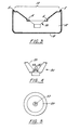
- FIGURE 2 shows a cross-sectional view of a rotomolded product comprising two speaker enclosures 1 and 2 fitting together along watertight separation line 3.
- FIGURE 3 shows a lip 5 which engages a sealing recess 7 when the speaker enclosures 1 and 2 are secured together.
- each speaker enclosure When separated, each speaker enclosure reveals unique speaker mounting arrangements and important structural parameters which function together to provide a much better speaker system than prior art devices.
- a speaker well 10 can be integrally molded into the speaker enclosure 1.
- mounting satellite recesses 4 are also molded in the rotomolding process. This allows speakers to be mounted below the surface of the speaker enclosure (see FIGURE 1). Because the recesses 4 even the mounting hardware is below the front plane of the enclosure. The most easily detectible benefit of this arrangement is that the speaker itself is much better protected from damage. Speakers traditionally were mounted atop a face plate (see FIGURE 6A) of the enclosure where a flat impact could create severe damage to the speaker, whereas the speakers in the invention, being mounted out of harm's way, are not subject to stresses from a flat frontal impact. Moreover, the speakers are protected from more pointed impact by a grill which is mounted within the speaker well above the speaker.
- the design and construction of the speakers of this invention were occasioned by an interest in providing even piston response at all bass bandwidth frequencies, as opposed to the traditional "flat", "equal energy per octave” response of traditional speakers.
- This requires very small enclosures and compression chambers: for example, an approximately .8 cubic foot enclosure is utilized for a 12 inch bass speaker. Another example is a 1.5 cubic foot enclosure used for a 15 inch speaker.
- enclosure areas of these dimensions for speakers of the diameters mentioned are radically different from the three to four cubic foot enclosures necessary in traditional speaker design.
- the speaker enclosures of the invention are typically nine inches or less from the front of the speaker motor to the back of the enclosure. This is substantially less than the 18-24 inch depths in industry standard boxes.
- the invention also utilizes two inch ports 16 as opposed to four inch ports in the prior art. The particular dimensions selected for each diameter speaker are based upon the following design parameters.
- All of the dimensions utilized in the present invention are selected to provide for lower cabinet air turbulence and a smooth low frequency rolloff below 200 Hertz. Limiting the amount of space behind the speaker to a range of from 2.5 cubic feet to 3.0 cubic feet for 15" diameter cone drivers, and proportionally smaller volumes for smaller cone drivers reduces the amount of trapped air behind the speaker cone. The less trapped air the less air the speaker must evacuate with each pulse and therefore detrimental oscillation and distortion effects are minimized. Moreover the low frequency rolloff below 200 Hertz is at approximately 6 decibels per octave as opposed to a typical > 18 db per octave steep rolloff at 40-50 Hz, slightly below speaker free air resonance. Smaller overall dimensions of these speakers makes them easier to transport in standard automobiles. Smaller size also reaps the benefit of lesser flex and cabinet resonance than traditional speakers. Avoiding flex and cabinet resonance is important to speaker efficiency. Cabinet vibration "damps" the speaker output, negatively affecting audio quality.
- the speaker enclosures of the invention do not use the traditional flexible baffleboard which has no central support. This has been omitted in favor of attaching the speaker magnet directly to the rear wall 18 of the enclosure. Moreover, each speaker mounting bolt is secured to supports and braces which are themselves attached to the rear wall 18 of the enclosure. This arrangement significantly reduces the damping action of vibrating speaker enclosure, and thus provides more acoustically accurate sound.
- sound deflection panels 26 or wave guides 27 are utilized to direct turbulence effects away from the speaker motor 30. This has the added advantage of using the turbulence related air movement to power feed the single or double 2 inch ports 16.
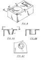
- Ports 16 can be located around the speaker motor 30 as illustrated in FIGURE 8. It will be understood however, by one of skill in the art that FIGURE 8 is used by way of illustration and not by way of limitation. Ports of the invention may be placed in any conventional location. All of the ports may be used or none of them as the manufacturer desires.
- Ports 16 are integrally formed in the face structure 8 of speaker enclosure 1 or 2 and can be a hollow conical or hollow frustoconical shape.
- Wall 15 of port 16 is in the range of from about 1 to about 4 inches in length, while the hollow defined by the wall is approximately 1 to 3 inches and is most preferably 2 inches in diameter.
- the port 16 can be, as mentioned, frustoconical or cylindrical; where a frustoconical shape is chosen the angle of taper is in the range of from 0 to 5 with the most preferable range being from 0 to 30. This is illustrated in FIGURES 8a and 8b.
- FIGURE 8c in also provided to illustrate a top plan view of a frustoconical port of the invention.
- a speaker motor 30 fitted with a novel x-shaped dust cap 33.
- the cap is positioned over the apex dome 35 of the speaker motor 30 and is mounted upon the diaphragm 39.
- the particular shape of the cap 33 is effective in eliminating any turbulence effects which are not suppressed in the speaker enclosure 1. It has been found that even though the enclosure of the invention prevents turbulence to a large extent, the dust cap 33 is beneficial to the arrangement. Increased benefits beyond those achieved by using the enclosure itself include greater SPL, better sound stage, greater sonic imaging and clearer acoustic centering of perceived sound origin point, and better tracking to mid-bass or high frequency transducers with corresponding greater articulation.
- a wave guide 26 can be installed within the compression chamber 12 of enclosure 1 or 2.
- a wave guide may be positioned in various locations within the compression chamber of a speaker enclosure, however, it has been found that a particular shape of wave guide is preferred for use with the rotomolded enclosure of the invention.
- FIGURE 9 depicts the wave guide 26 in a preferred location within a speaker enclosure in perspective view. Functionally, the wave guide 26 partially blocks the acoustic pathway from one of the speaker motors 30 to port 16 while still allowing full access by another speaker motor 30 to port 16. As will be appreciated, the degree of restriction of the acoustic pathway affects the quality of sound and the wave guide may be positioned in innumerable different locations to create different acoustic effects.
- the most preferred placement of the wave guide 26 is as shown in FIGURE 10, wherein the angle corner 28 of the wave guide 26 is immediately adjacent one of the speaker motors 30.
- the wave guide is constructed of rigid foam or wood and can be easily manufactured.
- a sound deflection panel 27 can be disposed between two speaker motors in a given speaker enclosure. This can partially or completely isolate the individual speaker motors and create, to varying degrees, relative to how complete the sound deflection panel is, two distinct compression chambers 12.
- the material can be wood, hard plastic or foam and is anchorable to the speaker enclosure by conventional means.
- FIGURE 11 shows an embodiment using a complete sound deflection panel.
Landscapes
- Physics & Mathematics (AREA)
- Engineering & Computer Science (AREA)
- Acoustics & Sound (AREA)
- Signal Processing (AREA)
- Health & Medical Sciences (AREA)
- Otolaryngology (AREA)
- Details Of Audible-Bandwidth Transducers (AREA)
- Obtaining Desirable Characteristics In Audible-Bandwidth Transducers (AREA)
Applications Claiming Priority (2)
| Application Number | Priority Date | Filing Date | Title |
|---|---|---|---|
| US20296594A | 1994-02-28 | 1994-02-28 | |
| US202965 | 1994-02-28 |
Publications (1)
| Publication Number | Publication Date |
|---|---|
| EP0669783A1 true EP0669783A1 (fr) | 1995-08-30 |
Family
ID=22751929
Family Applications (1)
| Application Number | Title | Priority Date | Filing Date |
|---|---|---|---|
| EP95102842A Withdrawn EP0669783A1 (fr) | 1994-02-28 | 1995-02-28 | Enceinte de haut-parleur rotomoulée |
Country Status (2)
| Country | Link |
|---|---|
| EP (1) | EP0669783A1 (fr) |
| CA (1) | CA2143565A1 (fr) |
Cited By (4)
| Publication number | Priority date | Publication date | Assignee | Title |
|---|---|---|---|---|
| WO2015014203A1 (fr) | 2013-08-01 | 2015-02-05 | Zhejiang Shenghui Lighting Co., Ltd | Dispositif d'éclairage à del et haut-parleur |
| US20170287462A1 (en) * | 2016-03-31 | 2017-10-05 | Harman Becker Automotive Systems Gmbh | Automatic noise control |
| CN107592597A (zh) * | 2016-07-06 | 2018-01-16 | 苹果公司 | 具有机械异相扬声器的电子设备 |
| EP3562173A4 (fr) * | 2016-12-21 | 2021-01-20 | Konstantin Rumyantsev | Porte-voix acoustique plein et procédé de fabrication correspondant |
Families Citing this family (3)
| Publication number | Priority date | Publication date | Assignee | Title |
|---|---|---|---|---|
| USD559545S1 (en) | 2006-07-27 | 2008-01-15 | Boyt Harness Company, L.L.C. | Container |
| USD559544S1 (en) | 2006-07-27 | 2008-01-15 | Boyt Harness Company, L.L.C. | Container |
| US7451872B1 (en) | 2006-07-27 | 2008-11-18 | Boyt Harness Company, Llc | Weaponry container having a rigid outer surface |
Citations (8)
| Publication number | Priority date | Publication date | Assignee | Title |
|---|---|---|---|---|
| US4168762A (en) * | 1978-01-13 | 1979-09-25 | Amanita Sound, Inc. | Loudspeaker enclosure |
| US4313032A (en) * | 1979-05-18 | 1982-01-26 | Invironments Inc. | Folded horn loudspeaker system |
| WO1982003961A1 (fr) * | 1981-04-28 | 1982-11-11 | George A Gale | Orifices d'event pour de haut-parleurs bass-reflex |
| FR2576544A1 (fr) * | 1985-01-30 | 1986-08-01 | Bouyer Cie Ets Paul | Procede de fabrication par moulage d'objets creux, dispositif pour la mise en oeuvre de ce procede et produits obtenus |
| EP0459682A2 (fr) * | 1990-05-31 | 1991-12-04 | Joe Speight Akroyd | Enceinte de haut-parleur avec des moyens d'absorption d'énergie |
| US5115884A (en) * | 1989-10-04 | 1992-05-26 | James Falco | Low distortion audio speaker cabinet |
| US5147986A (en) * | 1990-12-03 | 1992-09-15 | Tandy Corporation | Subwoofer speaker system |
| JPH05227591A (ja) * | 1992-02-10 | 1993-09-03 | Matsushita Electric Ind Co Ltd | スピーカ |
-
1995
- 1995-02-28 EP EP95102842A patent/EP0669783A1/fr not_active Withdrawn
- 1995-02-28 CA CA 2143565 patent/CA2143565A1/fr not_active Abandoned
Patent Citations (8)
| Publication number | Priority date | Publication date | Assignee | Title |
|---|---|---|---|---|
| US4168762A (en) * | 1978-01-13 | 1979-09-25 | Amanita Sound, Inc. | Loudspeaker enclosure |
| US4313032A (en) * | 1979-05-18 | 1982-01-26 | Invironments Inc. | Folded horn loudspeaker system |
| WO1982003961A1 (fr) * | 1981-04-28 | 1982-11-11 | George A Gale | Orifices d'event pour de haut-parleurs bass-reflex |
| FR2576544A1 (fr) * | 1985-01-30 | 1986-08-01 | Bouyer Cie Ets Paul | Procede de fabrication par moulage d'objets creux, dispositif pour la mise en oeuvre de ce procede et produits obtenus |
| US5115884A (en) * | 1989-10-04 | 1992-05-26 | James Falco | Low distortion audio speaker cabinet |
| EP0459682A2 (fr) * | 1990-05-31 | 1991-12-04 | Joe Speight Akroyd | Enceinte de haut-parleur avec des moyens d'absorption d'énergie |
| US5147986A (en) * | 1990-12-03 | 1992-09-15 | Tandy Corporation | Subwoofer speaker system |
| JPH05227591A (ja) * | 1992-02-10 | 1993-09-03 | Matsushita Electric Ind Co Ltd | スピーカ |
Non-Patent Citations (1)
| Title |
|---|
| PATENT ABSTRACTS OF JAPAN vol. 017, no. 680 (E - 1476) 14 December 1993 (1993-12-14) * |
Cited By (7)
| Publication number | Priority date | Publication date | Assignee | Title |
|---|---|---|---|---|
| WO2015014203A1 (fr) | 2013-08-01 | 2015-02-05 | Zhejiang Shenghui Lighting Co., Ltd | Dispositif d'éclairage à del et haut-parleur |
| EP2959221A4 (fr) * | 2013-08-01 | 2016-11-16 | Zhejiang Shenghui Lighting Co | Dispositif d'éclairage à del et haut-parleur |
| US20170287462A1 (en) * | 2016-03-31 | 2017-10-05 | Harman Becker Automotive Systems Gmbh | Automatic noise control |
| US10699690B2 (en) * | 2016-03-31 | 2020-06-30 | Harman Becker Automotive Systems Gmbh | Automatic noise control |
| CN107592597A (zh) * | 2016-07-06 | 2018-01-16 | 苹果公司 | 具有机械异相扬声器的电子设备 |
| CN107592597B (zh) * | 2016-07-06 | 2020-08-04 | 苹果公司 | 具有机械异相扬声器的电子设备 |
| EP3562173A4 (fr) * | 2016-12-21 | 2021-01-20 | Konstantin Rumyantsev | Porte-voix acoustique plein et procédé de fabrication correspondant |
Also Published As
| Publication number | Publication date |
|---|---|
| CA2143565A1 (fr) | 1995-08-29 |
Similar Documents
| Publication | Publication Date | Title |
|---|---|---|
| US4289929A (en) | Loudspeaker and enclosure combination | |
| US4903300A (en) | Compact and efficient sub-woofer system and method for installation in structural partitions | |
| US5067583A (en) | Polymer-filled audio loudspeaker cabinet | |
| US4964482A (en) | Loudspeaker enclosure | |
| US5875255A (en) | High power electroacoustic speaker system having wide band frequency response | |
| US5661271A (en) | Acoustic speaker enclosure having a stacked construction | |
| US5657392A (en) | Multi-way speaker with a cabinet defining a midrange driver pyramidal compartment | |
| US4325454A (en) | Speaker system which inverts and redirects the speaker backwave | |
| CN108781315B (zh) | 具有不同模块壳体几何形状和相似声学特性的扬声器模块 | |
| EP0669783A1 (fr) | Enceinte de haut-parleur rotomoulée | |
| US4440260A (en) | Bass-reflex loudspeaker system | |
| CN106034270A (zh) | 一种封闭式多腔体低音箱及内置该低音箱的电视机 | |
| US4509615A (en) | Multi-chamber enclosure for loudspeakers | |
| US20100215204A1 (en) | Speaker isolation system | |
| JP7474518B2 (ja) | オーディオラウドスピーカシステム | |
| US5647012A (en) | Tri-chamber speaker box | |
| US10645486B1 (en) | Loudspeaker system with passive radiators | |
| US6014448A (en) | Fluid coupled subwoofer acoustic enclosure system | |
| US7218749B1 (en) | Method for sound reproduction and pillar loudspeaker | |
| US5895896A (en) | Fluid coupled subwoofer acoustic enclosure system with port chamber | |
| WO2001065533A2 (fr) | Diffuseur acoustique depourvu de resonance | |
| US4785908A (en) | Vented loudspeaker | |
| US6108429A (en) | Speaker adapted for use as a center woofer in 3-dimensional sound system | |
| CN223942790U (zh) | 一种可改善音质的音箱 | |
| JPH01135294A (ja) | スピーカシステム |
Legal Events
| Date | Code | Title | Description |
|---|---|---|---|
| PUAI | Public reference made under article 153(3) epc to a published international application that has entered the european phase |
Free format text: ORIGINAL CODE: 0009012 |
|
| AK | Designated contracting states |
Kind code of ref document: A1 Designated state(s): AT BE CH DE DK ES FR GB GR IE IT LI LU MC NL PT SE |
|
| 17P | Request for examination filed |
Effective date: 19951204 |
|
| 17Q | First examination report despatched |
Effective date: 19960117 |
|
| STAA | Information on the status of an ep patent application or granted ep patent |
Free format text: STATUS: THE APPLICATION IS DEEMED TO BE WITHDRAWN |
|
| 18D | Application deemed to be withdrawn |
Effective date: 19960528 |