EP0670193A2 - Spannvorrichtung mit ausdehnbarem Spanndorn - Google Patents
Spannvorrichtung mit ausdehnbarem Spanndorn Download PDFInfo
- Publication number
- EP0670193A2 EP0670193A2 EP95400218A EP95400218A EP0670193A2 EP 0670193 A2 EP0670193 A2 EP 0670193A2 EP 95400218 A EP95400218 A EP 95400218A EP 95400218 A EP95400218 A EP 95400218A EP 0670193 A2 EP0670193 A2 EP 0670193A2
- Authority
- EP
- European Patent Office
- Prior art keywords
- mandrel
- gripping device
- cavity
- blades
- piston
- Prior art date
- Legal status (The legal status is an assumption and is not a legal conclusion. Google has not performed a legal analysis and makes no representation as to the accuracy of the status listed.)
- Ceased
Links
- 230000000295 complement effect Effects 0.000 claims description 4
- 230000007423 decrease Effects 0.000 claims description 3
- 230000005489 elastic deformation Effects 0.000 claims description 2
- 230000037431 insertion Effects 0.000 claims 1
- 238000003780 insertion Methods 0.000 claims 1
- KWGRBVOPPLSCSI-WPRPVWTQSA-N (-)-ephedrine Chemical compound CN[C@@H](C)[C@H](O)C1=CC=CC=C1 KWGRBVOPPLSCSI-WPRPVWTQSA-N 0.000 description 3
- 238000006073 displacement reaction Methods 0.000 description 2
- 238000004519 manufacturing process Methods 0.000 description 2
- 239000000463 material Substances 0.000 description 2
- 238000000465 moulding Methods 0.000 description 2
- 230000005641 tunneling Effects 0.000 description 2
- 239000012530 fluid Substances 0.000 description 1
- 238000009434 installation Methods 0.000 description 1
- 238000003754 machining Methods 0.000 description 1
- 238000012423 maintenance Methods 0.000 description 1
- 238000012986 modification Methods 0.000 description 1
- 230000004048 modification Effects 0.000 description 1
Images

Classifications
-
- E—FIXED CONSTRUCTIONS
- E04—BUILDING
- E04G—SCAFFOLDING; FORMS; SHUTTERING; BUILDING IMPLEMENTS OR AIDS, OR THEIR USE; HANDLING BUILDING MATERIALS ON THE SITE; REPAIRING, BREAKING-UP OR OTHER WORK ON EXISTING BUILDINGS
- E04G21/00—Preparing, conveying, or working-up building materials or building elements in situ; Other devices or measures for constructional work
- E04G21/14—Conveying or assembling building elements
- E04G21/142—Means in or on the elements for connecting same to handling apparatus
Definitions
- the present invention relates to a gripping device for a handling machine comprising an expandable mandrel which is introduced into a hole or a recess of the object to be manipulated and then blocked in the latter by expansion.
- Such a device can be used, in particular, for the handling of segments for lining tunnels.
- the segments are concrete segments assembled to form circular rings which, placed end to end, constitute the finished wall of a tunnel. They must be transported from the starting well of the tunnel to the TBM by wagons, unloaded from the wagons, transported from the stopping point of the wagons to a placement device called an erector, then taken up by the erector to be put in position in the tunnel. There are therefore at least two successive grips to be made on each segment which must be carried out in a difficult ambient environment and in a limited space, reasons for which we seek to use solutions limiting human interventions.
- Another solution is to use suction cups whose shape matches that of the underside of the segment. This solution is not safe because there is no positive grip on the segment.
- expandable mandrels intended to be engaged in cylindrical holes have been used, constituted by blades or shoes arranged around a frustoconical central core whose axial displacement causes the spacing of the fingers or shoes.
- This type of mandrel is not reliable because the connection with the object to be handled is ensured only by friction and is broken when the system which controls the movements of the core accidentally becomes inoperative.
- the object of the present invention is to provide a gripping device with an expandable mandrel which is reliable, easy to use and does not require any manual intervention for its fixing on the object to be manipulated and its release.
- the gripping device which is the subject of the present invention is characterized in that it comprises a mandrel constituted by a bell-shaped part the lower part of which is flared and formed by blades which can be radially stressed so that this lower part takes a cylindrical external shape by elastic deformation of the lamellae.
- the mandrel is introduced into a cavity formed in said object and whose shape is complementary to that of the lower part of the unstressed mandrel.
- the gripping device further comprises a locking piece which can be inserted into the mandrel, from below, and which maintains the blades in their relaxed position after its introduction into the cavity of the object to be handled.
- the thickness of the blades decreases from their end to their root. Thanks to this design, the mandrel cannot be released from the cavity, after locking, even in the event of accidental failure of the control system of the locking piece.
- the mandrel is fixed to the piston of a jack intended to be mounted on a handling device, and a tubular part, integral with the jack body and arranged coaxially with it forms a cylindrical housing in which the mandrel can be retracted by taking its cylindrical shape.
- the piston of this first cylinder is integral with a second cylinder whose piston is provided with a sliding rod in an axial bore of the piston of the first cylinder and at the end of which the part is fixed lock.
- Said tubular part can advantageously be used for centering the mandrel relative to the cavity which is to receive it.
- provision will be made at the front of the cavity and coaxially with the latter, a cylindrical chamber whose diameter will be slightly greater than the outside diameter of said part and whose entry will be flared.
- the cavity will be formed in the object to be handled during manufacture by molding or machining.
- this cavity can be formed in an insert (insert) embedded in the material during molding.
- This part will have the shape of a pot comprising an upper part in which will be formed the cylindrical chamber capable of receiving with a small clearance the centering part of the gripping device, and a lower part in which will be formed the cavity whose shape will be complementary to that of the lower part of the unstressed mandrel, the entry of this cavity having a diameter substantially equal to the inside diameter of the guide piece and its depth being greater than the height of the part of the mandrel which is there adjusts, so as to provide a housing for the locking piece.
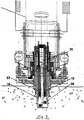
- the gripping device shown in the drawings is mounted on a chassis 8 constituting an element of a segment handling device in a tunneling machine, this chassis being mounted on a support structure integral with the shield of the tunneling machine so as to be able to rotate around the 'axis of the latter and to be moved radially to be able to set up the segments in the different positions they must occupy in the tunnel.
- the gripping member proper which is called a "mandrel" in the description and the claims, consists of a bell-shaped piece 10 which is pierced with a hole at its top for fixing to an operating member and whose lower part, slightly flared, is formed of blades 11.
- the elasticity of these blades and their spacing are sufficient for it to be possible to deform them and give the mandrel a cylindrical external shape when it is compressed radially.
- the mandrel 10 is fixed to the lower end of a tubular piece 12 constituting the piston of a jack 14 mounted on the chassis 8 by means of a ball joint 16 making it possible to modify the orientation of the gripping device with respect to to the chassis.
- the cylinder body 14 has a cylindrical extension 22 constituting a centering piece of the mandrel; in the retracted position, the mandrel is housed in this centering piece where it is maintained in its cylindrical shape ( Figure 2).
- the piston 12 At its end opposite to that where the mandrel 10 is fixed, the piston 12 has a tubular extension constituting a jack 24, the piston 26 of which is provided with a rod 28 which slides in the axial bore of the piston 12.
- a locking piece frustoconical 30 is fixed to the end of the rod 28.
- the part 30, the largest diameter of which is slightly less than the internal diameter of the part centering 22 is housed in the latter, at the end of the mandrel.
- the mandrel is intended to be introduced into an insert 18 which is embedded in the concrete during the manufacture of the segment 20.
- the insert is constituted by a pot-shaped part comprising an upper, cylindrical part capable of receiving the part of centering 22 and a lower part whose inner surface is frustoconical and complementary to that of the unstressed mandrel and forms a cavity 21 capable of receiving the mandrel.
- the entry of the insert is flared and the end of the part 22 is chamfered to facilitate the introduction of the part into the insert.
- the diameter of the small base of the cavity 21 is equal to the internal diameter of the part 22 and its depth is greater than the height of the part of the mandrel which adapts to it when it is unstressed (FIG. 3) so as to provide a housing for the locking piece 30.
- the mandrel is brought into the axis of the insert by displacement of the chassis 8 of the handling device and orientation of the jack 14.
- the centering piece 22 is then introduced into the upper part of the insert, the mandrel 10 and the locking piece 30 being retracted inside the piece 22.
- the jack 14 is then supplied with pressurized fluid to actuate the piston 12 which moves the mandrel 10 and the piece 30 and introduced them into the lower part of the insert (left part of Figure 3).
- the cylinder 14 remaining supplied, the cylinder 24 is supplied to actuate the piston 26 and bring the part 30 into the locking position inside the mandrel (right part of FIG. 3).
- the segment is then positively linked to the chassis 8 of the handling device and can be brought, by means of the latter, into the desired position. After installation, the reverse operations are carried out to separate the chuck from the segment.
- the interior and exterior surfaces of the mandrel do not have the same angle at the apex, the angle of the interior surface being smaller than that of the exterior surface; this results from the fact that the thickness (radial dimension) of the blades decreases from their end to their root.
- This shape of the blades ensures positive maintenance of the load regardless of the mandrel / insert and mandrel / locking part friction coefficients. Thanks to this shape, the part 30 ensures the locking of the mandrel in the insert in the absence of any hydraulic support by the piston 26.
- the device which is the subject of the invention can be used as a gripping means on various handling machines such as cranes, hoists, etc. It can also be used as a means of fixing different materials or devices to a wall or other support. It is also understood that all the modifications which can be made to the embodiment described by the use of equivalent technical means fall within the scope of the invention.
Landscapes
- Engineering & Computer Science (AREA)
- Architecture (AREA)
- Mechanical Engineering (AREA)
- Civil Engineering (AREA)
- Structural Engineering (AREA)
- Manipulator (AREA)
Applications Claiming Priority (2)
| Application Number | Priority Date | Filing Date | Title |
|---|---|---|---|
| FR9401212 | 1994-02-03 | ||
| FR9401212A FR2715646B1 (fr) | 1994-02-03 | 1994-02-03 | Dispositif de préhension à mandrin expansible. |
Publications (2)
| Publication Number | Publication Date |
|---|---|
| EP0670193A2 true EP0670193A2 (de) | 1995-09-06 |
| EP0670193A3 EP0670193A3 (de) | 1995-12-20 |
Family
ID=9459730
Family Applications (1)
| Application Number | Title | Priority Date | Filing Date |
|---|---|---|---|
| EP95400218A Ceased EP0670193A3 (de) | 1994-02-03 | 1995-02-02 | Spannvorrichtung mit ausdehnbarem Spanndorn. |
Country Status (2)
| Country | Link |
|---|---|
| EP (1) | EP0670193A3 (de) |
| FR (1) | FR2715646B1 (de) |
Cited By (2)
| Publication number | Priority date | Publication date | Assignee | Title |
|---|---|---|---|---|
| CN103212731A (zh) * | 2013-04-01 | 2013-07-24 | 浙江欧迪恩传动科技股份有限公司 | 一种等速万向节钟形壳内撑夹具 |
| CN104493229A (zh) * | 2014-12-25 | 2015-04-08 | 重庆创隆实业有限公司 | 汽车皮带轮精车用夹具 |
Family Cites Families (3)
| Publication number | Priority date | Publication date | Assignee | Title |
|---|---|---|---|---|
| GB252851A (en) * | 1925-04-25 | 1926-06-10 | Alfred Herbert | Improvements in work-chucking devices for lathes or other machine tools |
| DD95968A1 (de) * | 1972-02-24 | 1973-02-20 | ||
| DE2460368A1 (de) * | 1974-12-20 | 1976-06-24 | Scharmann & Co | Einrichtung zum indexieren eines beweglichen gegenueber einem feststehenden maschinenteil, insbesondere fuer werkzeugmaschinen |
-
1994
- 1994-02-03 FR FR9401212A patent/FR2715646B1/fr not_active Expired - Fee Related
-
1995
- 1995-02-02 EP EP95400218A patent/EP0670193A3/de not_active Ceased
Cited By (2)
| Publication number | Priority date | Publication date | Assignee | Title |
|---|---|---|---|---|
| CN103212731A (zh) * | 2013-04-01 | 2013-07-24 | 浙江欧迪恩传动科技股份有限公司 | 一种等速万向节钟形壳内撑夹具 |
| CN104493229A (zh) * | 2014-12-25 | 2015-04-08 | 重庆创隆实业有限公司 | 汽车皮带轮精车用夹具 |
Also Published As
| Publication number | Publication date |
|---|---|
| FR2715646A1 (fr) | 1995-08-04 |
| EP0670193A3 (de) | 1995-12-20 |
| FR2715646B1 (fr) | 1996-04-05 |
Similar Documents
| Publication | Publication Date | Title |
|---|---|---|
| KR102195790B1 (ko) | 클램프 시스템, 클램프 시스템용 파지 장치 및 클램프 시스템 사용 방법 | |
| EP1412107B1 (de) | Dehnungswerkzeug für aufweitzange | |
| EP2459350A1 (de) | Verfahren zur entfernung von festmontierten ringförmigen elementen in bohrungen, im besondereren blindbohrungen, von teilen | |
| FR2601732A1 (fr) | Dispositif de liaison a separation rapide et application d'un tel dispositif a la realisation de connecteurs a deverrouillage rapide | |
| EP0976482B1 (de) | Zentrier- und Spannvorrichtung, insbesondere für Teile beim Wagenaufbau | |
| EP0338942B1 (de) | Kupplung mit Ventilen und äusserer Schiebehülse | |
| FR2860843A1 (fr) | Dispositif de liaison a boulon de palier | |
| EP0670193A2 (de) | Spannvorrichtung mit ausdehnbarem Spanndorn | |
| EP0455558B1 (de) | Vorrichtung zum zeitweiligen Festhalten einer Achse in einem Körper, insbesondere Lenksäulenummantelung | |
| FR2681541A1 (fr) | Dispositif amovible d'assemblage de pieces presentant chacune un trou. | |
| EP2211001B1 (de) | Schalung zum Giessen von einer Betonmauer, Anordnung von miteinander verknüpften Schalungen | |
| EP3666432A1 (de) | Vorrichtung zur festen verbindung einer bohrvorrichtung mit einem bohrgitter, das einen kugelspannsatz umfasst | |
| CA1301637C (fr) | Systeme d'accrochage et de tensionement a distance d'un element allonge | |
| FR2918723A1 (fr) | Piece de liaison pour le montage et le demontage d'un accessoire amovible sur une structure de support fixe. | |
| FR2975323A1 (fr) | Dispositif pour l'extraction de bague | |
| EP2392750B1 (de) | Bewegliche Befestigung zum Abstützen und Befestigen einer Struktur an einer Wand, die mit einem Adapter ausgestattet ist | |
| CA1272893A (fr) | Gyroscope a entrainement par ressort | |
| FR3019537B1 (fr) | Dispositif de maintien de bouteilles | |
| EP0364380B1 (de) | Anschlusssystem, insbesondere für unter hohem Druck stehende hydraulische Leitung | |
| EP0109405B1 (de) | Einrichtung zum greifen von gegenständen für manipulator vom robotertyp | |
| EP0666388A1 (de) | In einem Gegenstand eingebauter Einsatz zur Ermöglichung seines Greifens mittels einer Vorrichtung versehen mit spreizbarem Spanndorm | |
| EP3488964A1 (de) | Vorrichtung zur handhabung einer hohlachse zum erzeugen einer schwenkbaren verbindung zwischen einem ersten und einem zweiten element | |
| FR2545740A1 (fr) | Dispositif de support de noyau d'emboitement pour moule centrifuge de tuyaux en fonte a emboitement | |
| EP0067751B1 (de) | Einrichtung zum Ein- und Festsetzen einer Schraube oder eines Bolzens in einer Sackbohrung | |
| FR2721840A1 (fr) | Pistolet de mise en place d'une charge de scellement et d'une cartouche d'ancrage dans un trou borgne |
Legal Events
| Date | Code | Title | Description |
|---|---|---|---|
| PUAI | Public reference made under article 153(3) epc to a published international application that has entered the european phase |
Free format text: ORIGINAL CODE: 0009012 |
|
| AK | Designated contracting states |
Kind code of ref document: A2 Designated state(s): BE CH DE ES GB IT LI NL PT |
|
| PUAL | Search report despatched |
Free format text: ORIGINAL CODE: 0009013 |
|
| AK | Designated contracting states |
Kind code of ref document: A3 Designated state(s): BE CH DE ES GB IT LI NL PT |
|
| 17P | Request for examination filed |
Effective date: 19960610 |
|
| 17Q | First examination report despatched |
Effective date: 19970716 |
|
| GRAG | Despatch of communication of intention to grant |
Free format text: ORIGINAL CODE: EPIDOS AGRA |
|
| STAA | Information on the status of an ep patent application or granted ep patent |
Free format text: STATUS: THE APPLICATION HAS BEEN REFUSED |
|
| 18R | Application refused |
Effective date: 19981226 |