EP0670281A2 - Tête tournante pour dispositifs de dépôt de rubans de fibre textiles - Google Patents
Tête tournante pour dispositifs de dépôt de rubans de fibre textiles Download PDFInfo
- Publication number
- EP0670281A2 EP0670281A2 EP95108297A EP95108297A EP0670281A2 EP 0670281 A2 EP0670281 A2 EP 0670281A2 EP 95108297 A EP95108297 A EP 95108297A EP 95108297 A EP95108297 A EP 95108297A EP 0670281 A2 EP0670281 A2 EP 0670281A2
- Authority
- EP
- European Patent Office
- Prior art keywords
- sliver
- turntable
- channel
- outlet
- band channel
- Prior art date
- Legal status (The legal status is an assumption and is not a legal conclusion. Google has not performed a legal analysis and makes no representation as to the accuracy of the status listed.)
- Granted
Links
Images


Classifications
-
- B—PERFORMING OPERATIONS; TRANSPORTING
- B65—CONVEYING; PACKING; STORING; HANDLING THIN OR FILAMENTARY MATERIAL
- B65H—HANDLING THIN OR FILAMENTARY MATERIAL, e.g. SHEETS, WEBS, CABLES
- B65H54/00—Winding, coiling, or depositing filamentary material
- B65H54/76—Depositing materials in cans or receptacles
- B65H54/80—Apparatus in which the depositing device or the receptacle is rotated
-
- B—PERFORMING OPERATIONS; TRANSPORTING
- B65—CONVEYING; PACKING; STORING; HANDLING THIN OR FILAMENTARY MATERIAL
- B65H—HANDLING THIN OR FILAMENTARY MATERIAL, e.g. SHEETS, WEBS, CABLES
- B65H2701/00—Handled material; Storage means
- B65H2701/30—Handled filamentary material
- B65H2701/31—Textiles threads or artificial strands of filaments
Definitions
- the present invention relates to a turntable for sliver storage devices with a band channel.
- a turntable for depositing slivers in sliver cans with a channel is known, the sliver opening from an inlet part above and in the axis of rotation of the turntable via an arcuate curvature in plan to an underlying, tangent to the turntable and leads approximately to the circumference of the outlet part.
- the channel has a straight and radial intermediate piece between its inlet part and its outlet part. Particularly in the case of modern, very fast-running machines with such turntables, it has been found that such channels lead to unfavorable and uneven sliver storage.
- the channel is composed of at least two pipe elbows bent in a circular arc. Due to the telescopic composition of the elbows, the course of the channel can be adapted to the different can diameters.
- the two pipe elbows are provided with straight ends at their connection point.
- this device also has the disadvantage that the sliver has a pipe elbow edge must be performed and runs through a changed channel cross-section. In the case of fast machines in particular, such a design is not well suited for high accuracy when laying the sliver and for gentle handling of the sliver. Deposits can form on the edge, which peel off from time to time and lead to irregularities in the sliver.
- the object is achieved by the features of claim 1. If the band channel is formed from a piece of pipe with two circular arcs that merge directly into one another, only slight acceleration forces act on the fiber band. Because no straight piece is arranged between the arcs, the sliver is guided gently in the sliver channel, so that practically no permanent deformation after storage in the sliver can is detected in the sliver. This even and gentle storage of the sliver is of great importance in the modern, very precise and fast draw frames and cards, so as not to destroy the previously produced sliver again during storage.
- both arcs have essentially the same radii, this has a positive effect on the acceleration of the sliver off, since in this case the sliver is wound in large radii and thus small deflection forces act on the sliver.
- both arcs have a common tangent at their transition, a constant and edge-free transition of the arcs is guaranteed.
- the sliver channel should consist exclusively of circular arcs.
- the circular arc-shaped run-out of the band channel has a positive effect on a low-force placement of the sliver.
- An angle of 130 ° has proven itself for an inclination of the planes in which the arcs are arranged.
- the transition of the band channel to the horizontal preferably takes place at a deposit angle of approximately 15 °.
- the band channel and / or a cover of the turntable is made of stainless steel.
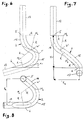
- FIG. 1 shows a section through a turntable 1 according to the invention with a belt channel 2.
- Sliver enters the belt channel 2 in an inlet 5, passes through the belt channel 2 and exits the belt channel 2 at an outlet 6.
- the inlet 5 of the band channel 2 is arranged centrally in the turntable 1.
- a casting compound 4 connects the band channel 2 to a plate holder 3. This ensures that the band channel 2 is always correctly positioned and does not change its position due to external influences.
- the band channel 2 is also fixed at its outlet 6 with a casting compound 8.
- the casting compound 8 ensures that a gap-free transition between the band channel 2 and the turntable 1 on the underside of the turntable 1 is ensured.
- the underside of the turntable 1 is provided with a cover 7.
- the cover 7 is advantageously made of stainless steel. This ensures that extremely little friction and little wear occurs between the sliver 10 deposited in a sliver can and the underside of the turntable 1. In addition, complex processing of the bottom of the turntable 1, in particular grinding and filling of the cast aluminum turntable 1, is avoided. Less care must also be taken when pouring the band channel 2 with the casting compound 8 into the turntable 8.
- the device according to the invention advantageously has the effect that, with a large distance 9, no sliver is flung out over the edge of the sliver can during storage. Rather, the sliver is deposited in the spinning can 10 without a large radial speed component. This ensures a particularly even and orderly placement of the sliver. In addition, the orderly filing also ensures that the sliver is conveniently pulled out of the can 10. This is particularly important at high delivery speeds. The ejection of the sliver can be observed in particular in the first layers of the sliver deposited in the spinning can 10 in known generic devices.
- An axis of rotation 11 of the turntable 1 is a tangent to the inlet bend of the band channel 2.
- a center line 14 of the band channel 2 runs from the axis of rotation 11 at the inlet 5 of the band channel 2 to the outlet 6 and essentially represents the deformation of the fiber band when passing through the band channel 2.
- the center line 14 of the band channel 2 is shown in an XYZ coordinate system.
- the coordinate system is laid out in such a way that the inlet has 5 X and Y values 0 and the outlet 6 has Y and Z values 0.
- the center line 14 is formed from two arcs.
- the first arc has a center M1 and designates the outlet arch.
- the inlet arch has its center in a center M2.
- Both arches have the same radius R.
- the same radius R ensures that the fiber sliver is subjected to the lowest possible load when passing through the sliver channel 2.
- the radius R should be as large as possible so that there is a uniform force on the sliver during the entire passage through the sliver channel 2.
- the arcs which are formed around the center M1 and M2 merge directly into one another.
- the arcs therefore have a common tangent T at a turning point W.
- the end of the outlet bend 15 is determined by a fixed depositing radius Ra, a depositing angle ⁇ 1 of the exit tangent to the surface of the turntable, which corresponds to the Y-axis of the coordinate system, and by a height H of the belt channel 2.
- the inlet bend 16 is shorter than the outlet bend 15.
- the inclination of the plane E at an angle ⁇ to the Y axis ensures a short path through the band channel 2 which is low in acceleration for the sliver.
- Figure 3 shows a representation of the inclination of the plane E of the inlet bend 16 to the plane A of the outlet curve 15.
- the angle of inclination ⁇ is approximately 125 ° in the exemplary embodiment shown.
- the planes E and A intersect in the tangent T.
- the center points M1 and M2 of the two arcs of the band channel 2 are also in the plane A and E.
- a view B in FIG. 3 is shown in FIG.
- FIG. 4 shows a representation of the center line 14 of the band channel 2, in which the inlet bend 16 is shown undistorted.
- the inlet bend 16 has the radius R around the center M2.
- the inlet bend 16 extends over an angle ⁇ 1, which here is approximately 70 °.
- FIG. 4 shows, in addition to the outlet bend 15 and the inlet bend 16, a straight line 12 in front of the inlet bend 16.
- the straight line 12 is arranged in the semi-finished product for manufacturing reasons. This ensures that the arches 15 and 16 bend with tolerance, since the workpiece can be clamped in a bending device.
- the straight line 12 is separated from the arches 15 and 16 during the finishing of the band channel 2. By deburring the inlet 5, low-friction insertion of the sliver into the sliver channel 2 is ensured.
- FIG. 5 shows a view in the direction of arrow C in FIG. 3.
- the center line 14 of the band channel 2 has a radius R and the center point M1 in the outlet arch 15.
- Inlet bend 16 merges directly into outlet bend 15 at inflection point W.
- the outlet bend 15 has an angle ⁇ 2 which is approximately 127 °.
- a straight line 13 is arranged after the outlet curve 15 in the semi-finished product. As with the straight line 12 on the inlet bend 16, the straight line 13 on the outlet bend 15 ensures that the preferably stainless steel tube, which is used for forming the band channel 2, is securely clamped in the bending tool.
- the straight line 13 is cut off when the band channel 2 is completed.
- the end of the outlet bend 15 is preferably deburred.
- FIG. 6 shows a band channel 2 in a view radially to the turntable 1.
- the straight lines 12 and 13 separated in the finished product are shown in dashed lines.
- the inlet bend 16 forms a common tangent T with the outlet bend 15 at the turning point W.
- Both the inlet bend 16 and the outlet bend 15 have the same bending radius R.
- This has proven to be particularly advantageous since the acceleration forces on the fiber sliver are particularly uniform.
- the outlet 6 is designed such that it ends flush with the bottom of the turntable 1.
- the outlet bend 15 enters the bottom of the turntable 2 at an angle ⁇ 1.
- a placement angle of 15 ° has proven to be advantageous for a distortion-free placement of the sliver.
- a radius R of approximately 80 mm has been found to be particularly gentle on the sliver.
- FIG. 7 shows a representation of the band channel 2 in the direction of rotation of the turntable 1.
- the direct transition of the inlet bend 16 into the outlet bend 15 into the turning point W is also shown here.
- the height H of the sliver channel 2 is predetermined by the structural requirements of the sliver storage device.
- the choice of the circular arcs used for the inlet arch 16 and the outlet arch 15, as well as the inclination of the planes B and A with respect to one another, is based on this height H and on a further predetermined storage radius Ra.
- FIG. 8 shows a view of the band channel 2 in the axial direction of the turntable. It can clearly be seen from the illustration in FIG. 8 that a round tube was used as the starting material in the exemplary embodiment shown. According to the invention, however, other cross sections can also be used for the band channel.
- the storage radius Ra is approximately 140 mm. This has proven to be advantageous when storing sliver in spinning cans 10 with a diameter of 450 mm. This ensures warp-free storage of the sliver with optimal filling of the sliver can 10 with sliver.
- the present invention is not restricted to the exemplary embodiment shown.
Landscapes
- Spinning Or Twisting Of Yarns (AREA)
- Coiling Of Filamentary Materials In General (AREA)
- Metal Extraction Processes (AREA)
- Preliminary Treatment Of Fibers (AREA)
- Cleaning In General (AREA)
Applications Claiming Priority (3)
| Application Number | Priority Date | Filing Date | Title |
|---|---|---|---|
| DE4131134 | 1991-09-19 | ||
| DE4131134A DE4131134A1 (de) | 1991-09-19 | 1991-09-19 | Drehteller fuer faserbandablageeinrichtungen |
| EP92114809A EP0532964B1 (fr) | 1991-09-19 | 1992-08-29 | Tête tournante pour dispositifs de dépÔt de rubans de fibres textiles |
Related Parent Applications (1)
| Application Number | Title | Priority Date | Filing Date |
|---|---|---|---|
| EP92114809.4 Division | 1992-08-29 |
Publications (3)
| Publication Number | Publication Date |
|---|---|
| EP0670281A2 true EP0670281A2 (fr) | 1995-09-06 |
| EP0670281A3 EP0670281A3 (fr) | 1996-01-10 |
| EP0670281B1 EP0670281B1 (fr) | 1998-07-15 |
Family
ID=6440942
Family Applications (2)
| Application Number | Title | Priority Date | Filing Date |
|---|---|---|---|
| EP92114809A Expired - Lifetime EP0532964B1 (fr) | 1991-09-19 | 1992-08-29 | Tête tournante pour dispositifs de dépÔt de rubans de fibres textiles |
| EP95108297A Revoked EP0670281B1 (fr) | 1991-09-19 | 1992-08-29 | Tête tournante pour dispositifs de dépÔt de rubans de fibre textiles |
Family Applications Before (1)
| Application Number | Title | Priority Date | Filing Date |
|---|---|---|---|
| EP92114809A Expired - Lifetime EP0532964B1 (fr) | 1991-09-19 | 1992-08-29 | Tête tournante pour dispositifs de dépÔt de rubans de fibres textiles |
Country Status (7)
| Country | Link |
|---|---|
| US (1) | US5317786A (fr) |
| EP (2) | EP0532964B1 (fr) |
| JP (1) | JPH06218339A (fr) |
| CN (1) | CN1027157C (fr) |
| CZ (2) | CZ281572B6 (fr) |
| DE (3) | DE4131134A1 (fr) |
| RU (1) | RU2061642C1 (fr) |
Cited By (2)
| Publication number | Priority date | Publication date | Assignee | Title |
|---|---|---|---|---|
| DE102004058573A1 (de) * | 2004-12-03 | 2006-06-08 | Trützschler GmbH & Co KG | Ablageteller für Faserbandablagevorrichtungen, insbesondere von Strecken und Karden |
| DE102012007415A1 (de) | 2012-02-07 | 2013-08-08 | TRüTZSCHLER GMBH & CO. KG | Vorrichtung an einer Spinnereivorbereitungsmaschine, insbesondere Karde, Strecke, Kämmmaschine o. dgl., mit einem Ablageteller für Faserbandablagevorrichtungen |
Families Citing this family (17)
| Publication number | Priority date | Publication date | Assignee | Title |
|---|---|---|---|---|
| DE4143345B4 (de) * | 1991-12-04 | 2007-03-22 | Rieter Ingolstadt Spinnereimaschinenbau Ag | Drehteller einer Spinnereivorbereitungsmaschine |
| DE4139910B4 (de) * | 1991-12-04 | 2005-07-14 | Rieter Ingolstadt Spinnereimaschinenbau Ag | Bandkanal |
| DE10063031A1 (de) * | 2000-12-18 | 2002-06-20 | Rieter Ingolstadt Spinnerei | Textilmaschine |
| DE10127815A1 (de) * | 2001-06-07 | 2002-12-12 | Truetzschler Gmbh & Co Kg | Drehteller für Faserbandablageeinrichtungen, insbesondere an Strecken, Karden u. dgl. |
| DE10127814A1 (de) * | 2001-06-07 | 2002-12-12 | Truetzschler Gmbh & Co Kg | Drehteller für Faserbandablageeinrichtungen, insbesondere an Strecken, Karden u. dgl. |
| US6694572B2 (en) | 2002-06-10 | 2004-02-24 | Trützschler GmbH & Co., KG | Sliver channel with reduced friction |
| US6568039B1 (en) | 2002-06-10 | 2003-05-27 | TRüTZSCHLER GMBH & CO. KG | Sliver channel with reduced friction |
| DE10334758B4 (de) * | 2002-08-19 | 2013-12-05 | Rieter Ingolstadt Gmbh | Drehteller einer Spinnereimaschine sowie Spinnereimaschine |
| DE102004034408A1 (de) * | 2004-07-16 | 2006-02-02 | Rieter Ingolstadt Spinnereimaschinenbau Ag | Drehteller für eine Faserbandablagevorrichtung |
| DE102004063027B4 (de) * | 2004-12-22 | 2017-10-12 | Trützschler GmbH & Co Kommanditgesellschaft | Vorrichtung an einer Spinnereivorbereitungsmaschine, z.B. Karde, Kardenstreckwerk, Strecke, Kämmmaschine o. dgl., zum Wechseln von Spinnkannen |
| CN101245506B (zh) * | 2008-03-27 | 2010-06-23 | 江苏凯宫机械股份有限公司 | 精梳机的圈条器 |
| CN103122513A (zh) * | 2011-11-18 | 2013-05-29 | 青岛云龙纺织机械有限公司 | 并条机v带式圈条盘装置 |
| CN104233518B (zh) * | 2014-09-02 | 2016-08-24 | 南通优旋圈条器有限公司 | 一种高光洁度的圈条器及其制备工艺 |
| DE102015001412B3 (de) * | 2015-02-06 | 2016-04-21 | ITA Technologietransfer GmbH | Verfahren zum Zuführen eines Stapelfaserbands zu einem Legekopf, Textilmaschine und Verfahren zum Nachrüsten einer Textilmaschine |
| CN105329677B (zh) * | 2015-09-29 | 2018-03-09 | 湖南海尚环境生物科技股份有限公司 | 物料循环搅拌机构及其控制使用方法和无水型生态厕所 |
| CN105478673B (zh) * | 2016-01-21 | 2017-12-12 | 黄永利 | 铝精铸导绵管一体圈条器及其铸造模具和制备方法 |
| CN119932777A (zh) * | 2024-02-01 | 2025-05-06 | 特吕茨施勒纺织机械(上海)有限公司 | 用于纺纱准备机器的圈条盘装置、纺纱准备机器以及制造圈条盘装置的方法 |
Family Cites Families (13)
| Publication number | Priority date | Publication date | Assignee | Title |
|---|---|---|---|---|
| NL236353A (fr) * | 1958-02-28 | |||
| CH372962A (de) * | 1959-09-08 | 1963-10-31 | Luwa Ag | Verfahren zum Ablegen eines endlosen Bandes |
| DE1115623B (de) * | 1960-08-19 | 1961-10-19 | Schubert & Salzer Maschinen | Drehteller fuer Faserbandablegeeinrichtungen von Strecken, Karden und anderen Spinnereimaschinen |
| NL272159A (fr) * | 1960-12-19 | |||
| DE1209030B (de) * | 1961-12-09 | 1966-01-13 | Schubert & Salzer Maschinen | Vorrichtung zum Verhueten von Faserband-stauungen in Drehtellerrohren von Faserbandablegevorrichtungen |
| DE2540148C3 (de) * | 1975-09-09 | 1980-06-26 | Barmag Barmer Maschinenfabrik Ag, 5630 Remscheid | Ablegevorrichtung fur Chemiefaserkabel und Arbeitsverfahren zum Betrieb der Vorrichtung |
| BR7601196A (pt) * | 1975-03-07 | 1976-09-14 | Barmag Barmer Maschf | Dispositivo transportador de cabo de fibras sinteticas,e,processo de sua operacao |
| DE2801010C2 (de) * | 1978-01-11 | 1980-01-24 | Rieter Deutschland Gmbh, 7000 Stuttgart | Drehteller zum Ablegen eines Faserbandes in eine Spinnkanne |
| CH639628A5 (de) * | 1979-10-01 | 1983-11-30 | Luwa Ag | Kannenpresse. |
| DE3118968A1 (de) * | 1981-05-13 | 1982-12-09 | Nordischer Maschinenbau Rud. Baader GmbH + Co KG, 2400 Lübeck | "vorrichtung zum ablegen eines faserbandes in eine spinnkanne" |
| DE3407135A1 (de) * | 1984-02-28 | 1985-08-29 | Zinser Textilmaschinen Gmbh, 7333 Ebersbach | Vorrichtung zum ablegen von lunte in eine rotierende kanne |
| DE3524601A1 (de) * | 1985-07-10 | 1987-01-15 | Truetzschler & Co | Vorrichtung zum antrieb einer faserbandeinlegeeinrichtung fuer eine rotierende spinnkanne, z.b. fuer karde, strecke |
| DE3810460A1 (de) * | 1988-03-26 | 1989-10-12 | Zinser Textilmaschinen Gmbh | Drehteller fuer eine strecke |
-
1991
- 1991-09-19 DE DE4131134A patent/DE4131134A1/de not_active Withdrawn
-
1992
- 1992-08-29 EP EP92114809A patent/EP0532964B1/fr not_active Expired - Lifetime
- 1992-08-29 DE DE59209419T patent/DE59209419D1/de not_active Revoked
- 1992-08-29 DE DE59205226T patent/DE59205226D1/de not_active Expired - Fee Related
- 1992-08-29 EP EP95108297A patent/EP0670281B1/fr not_active Revoked
- 1992-09-14 CZ CZ952766A patent/CZ281572B6/cs not_active IP Right Cessation
- 1992-09-14 CZ CS922826A patent/CZ281481B6/cs unknown
- 1992-09-18 US US07/947,345 patent/US5317786A/en not_active Expired - Lifetime
- 1992-09-18 JP JP4249207A patent/JPH06218339A/ja active Pending
- 1992-09-18 RU SU925052972A patent/RU2061642C1/ru active
- 1992-09-18 CN CN92111590A patent/CN1027157C/zh not_active Expired - Fee Related
Cited By (8)
| Publication number | Priority date | Publication date | Assignee | Title |
|---|---|---|---|---|
| DE102004058573A1 (de) * | 2004-12-03 | 2006-06-08 | Trützschler GmbH & Co KG | Ablageteller für Faserbandablagevorrichtungen, insbesondere von Strecken und Karden |
| GB2421033A (en) * | 2004-12-03 | 2006-06-14 | Truetzschler Gmbh & Co Kg | Coiler plate for sliver-coiling devices, especially of draw frames and carding machines |
| US7275287B2 (en) | 2004-12-03 | 2007-10-02 | Trutzschler Gmbh & Co. Kg | Coiler plate for silver-coiling devices, especially of draw frames and carding machines |
| GB2421033B (en) * | 2004-12-03 | 2009-03-11 | Truetzschler Gmbh & Co Kg | Coiler plate for sliver-coiling devices, especially of draw frames and carding machines |
| CN1781836B (zh) * | 2004-12-03 | 2012-05-02 | 特鲁菲舍尔股份有限公司及两合公司 | 长条卷绕装置的卷绕盘 |
| DE102004058573B4 (de) * | 2004-12-03 | 2017-10-12 | Trützschler GmbH & Co Kommanditgesellschaft | Ablageteller für Faserbandablagevorrichtungen, insbesondere von Strecken und Karden |
| DE102012007415A1 (de) | 2012-02-07 | 2013-08-08 | TRüTZSCHLER GMBH & CO. KG | Vorrichtung an einer Spinnereivorbereitungsmaschine, insbesondere Karde, Strecke, Kämmmaschine o. dgl., mit einem Ablageteller für Faserbandablagevorrichtungen |
| DE102012007415B4 (de) * | 2012-02-07 | 2025-11-13 | Trützschler Group SE | Vorrichtung an einer Spinnereivorbereitungsmaschine, insbesondere Karde, Strecke, Kämmmaschine o. dgl., mit einem Ablageteller für Faserbandablagevorrichtungen |
Also Published As
| Publication number | Publication date |
|---|---|
| JPH06218339A (ja) | 1994-08-09 |
| CZ282692A3 (en) | 1994-03-16 |
| EP0532964B1 (fr) | 1996-01-31 |
| CN1074881A (zh) | 1993-08-04 |
| EP0670281B1 (fr) | 1998-07-15 |
| EP0670281A3 (fr) | 1996-01-10 |
| EP0532964A1 (fr) | 1993-03-24 |
| CN1027157C (zh) | 1994-12-28 |
| US5317786A (en) | 1994-06-07 |
| DE4131134A1 (de) | 1993-06-17 |
| DE59209419D1 (de) | 1998-08-20 |
| CZ281481B6 (cs) | 1996-10-16 |
| CZ276695A3 (en) | 1996-07-17 |
| CZ281572B6 (cs) | 1996-11-13 |
| DE59205226D1 (de) | 1996-03-14 |
| RU2061642C1 (ru) | 1996-06-10 |
Similar Documents
| Publication | Publication Date | Title |
|---|---|---|
| EP0532964B1 (fr) | Tête tournante pour dispositifs de dépÔt de rubans de fibres textiles | |
| DE4139910B4 (de) | Bandkanal | |
| DE3332498A1 (de) | Verbesserung an offenendspinnmaschinen | |
| EP3371353B1 (fr) | Buse de sortie de fil à rainures s'étendant radialement au trou de buse | |
| DE1710038B2 (de) | Offenend-spinnvorrichtung | |
| DE3002026C2 (fr) | ||
| DE3345170A1 (de) | Verfahren und vorrichtung zur herstellung von seelengarn aus einem faserbaendchen | |
| EP1616828B1 (fr) | Tête tournante pour un dispositif d'emballage de rubains de fibres | |
| EP0489225B1 (fr) | Broche à retordre à double torsion avec dispositif d'enfilage pneumatique | |
| EP3686329A1 (fr) | Dispositif de charge et de décharge pour un dispositif pince-fil et dispositif pince-fil | |
| DE2010314A1 (de) | Vorrichtung zum Abzug und Aufwickeln von Garn bei Spinneinheiten von Maschinen zur Garnherstellung nach einem pneumatischmechanischen Verfahren, insbesondere mit Hilfe einer Unterdruck-Spinnkammer | |
| DE1602265A1 (de) | Drahtablaufbremse | |
| DE1115622B (de) | Drehteller zum Ablegen von Faserbaendern in Spinnkannen von Spinnerei-Vorbereitungsmaschinen | |
| CH629453A5 (en) | Winding unit of a textile machine with a winding roller | |
| DD214773B1 (de) | Vorrichtung zur erzielung gleichmaessig geformter drahtwindungen von windungsstegern | |
| EP4431648B1 (fr) | Compresseur de ruban de fibres pour un dispositif de filage à bout libre et dispositif de filage à bout libre | |
| EP0455190A1 (fr) | Condenseur de mèche sur une ailette | |
| DE725630C (de) | Einfuehrungsvorrichtung, insbesondere an Schraegwalzen-Richtmaschinen | |
| DE2218520A1 (de) | Aufwickelspulenrahmen fuer textilmaschinen, insbesondere fuer aufwickelspul- und texturiermaschinen sowie spindellose feinspinnmaschinen und andere aehnliche maschinen | |
| DD270550B3 (de) | Verfahren und vorrichtung zur herstellung von stahldrahtlitzen mit variablem verseilaufbau | |
| EP0182241B1 (fr) | Dispositif pour la filature à friction | |
| DE1029783B (de) | Verlegearm fuer Edenborn-Haspel | |
| DE2824652A1 (de) | Vorrichtung zur aufnahme eines faserbands | |
| DE3319747A1 (de) | Verfahren und vorrichtung zur unterbrechung des flyerluntentransports auf einer spinnmaschine | |
| EP1486594B1 (fr) | Tuyère de sortie de fil |
Legal Events
| Date | Code | Title | Description |
|---|---|---|---|
| PUAI | Public reference made under article 153(3) epc to a published international application that has entered the european phase |
Free format text: ORIGINAL CODE: 0009012 |
|
| 17P | Request for examination filed |
Effective date: 19950531 |
|
| AC | Divisional application: reference to earlier application |
Ref document number: 532964 Country of ref document: EP |
|
| AK | Designated contracting states |
Kind code of ref document: A2 Designated state(s): DE FR GB IT |
|
| PUAL | Search report despatched |
Free format text: ORIGINAL CODE: 0009013 |
|
| AK | Designated contracting states |
Kind code of ref document: A3 Designated state(s): DE FR GB IT |
|
| GRAG | Despatch of communication of intention to grant |
Free format text: ORIGINAL CODE: EPIDOS AGRA |
|
| 17Q | First examination report despatched |
Effective date: 19971119 |
|
| GRAG | Despatch of communication of intention to grant |
Free format text: ORIGINAL CODE: EPIDOS AGRA |
|
| GRAH | Despatch of communication of intention to grant a patent |
Free format text: ORIGINAL CODE: EPIDOS IGRA |
|
| GRAH | Despatch of communication of intention to grant a patent |
Free format text: ORIGINAL CODE: EPIDOS IGRA |
|
| GRAA | (expected) grant |
Free format text: ORIGINAL CODE: 0009210 |
|
| AC | Divisional application: reference to earlier application |
Ref document number: 532964 Country of ref document: EP |
|
| AK | Designated contracting states |
Kind code of ref document: B1 Designated state(s): DE FR GB IT |
|
| PG25 | Lapsed in a contracting state [announced via postgrant information from national office to epo] |
Ref country code: GB Free format text: LAPSE BECAUSE OF FAILURE TO SUBMIT A TRANSLATION OF THE DESCRIPTION OR TO PAY THE FEE WITHIN THE PRESCRIBED TIME-LIMIT Effective date: 19980715 |
|
| ITF | It: translation for a ep patent filed | ||
| REF | Corresponds to: |
Ref document number: 59209419 Country of ref document: DE Date of ref document: 19980820 |
|
| ET | Fr: translation filed | ||
| GBV | Gb: ep patent (uk) treated as always having been void in accordance with gb section 77(7)/1977 [no translation filed] |
Effective date: 19980715 |
|
| PLBI | Opposition filed |
Free format text: ORIGINAL CODE: 0009260 |
|
| PLBQ | Unpublished change to opponent data |
Free format text: ORIGINAL CODE: EPIDOS OPPO |
|
| PLBI | Opposition filed |
Free format text: ORIGINAL CODE: 0009260 |
|
| 26 | Opposition filed |
Opponent name: TRUETZSCHLER GMBH & CO.KG Effective date: 19990302 |
|
| PLBF | Reply of patent proprietor to notice(s) of opposition |
Free format text: ORIGINAL CODE: EPIDOS OBSO |
|
| PLAB | Opposition data, opponent's data or that of the opponent's representative modified |
Free format text: ORIGINAL CODE: 0009299OPPO |
|
| 26 | Opposition filed |
Opponent name: MAASLAND N.V. Effective date: 19990414 Opponent name: ZINSER TEXTILMASCHINEN GMBH Effective date: 19990413 Opponent name: TRUETZSCHLER GMBH & CO.KG Effective date: 19990302 |
|
| R26 | Opposition filed (corrected) |
Opponent name: TRUETZSCHLER GMBH & CO.KG * 19990413 ZINSER TEXTIL Effective date: 19990302 |
|
| PLBF | Reply of patent proprietor to notice(s) of opposition |
Free format text: ORIGINAL CODE: EPIDOS OBSO |
|
| PLBF | Reply of patent proprietor to notice(s) of opposition |
Free format text: ORIGINAL CODE: EPIDOS OBSO |
|
| PLBO | Opposition rejected |
Free format text: ORIGINAL CODE: EPIDOS REJO |
|
| APAC | Appeal dossier modified |
Free format text: ORIGINAL CODE: EPIDOS NOAPO |
|
| APAC | Appeal dossier modified |
Free format text: ORIGINAL CODE: EPIDOS NOAPO |
|
| APAE | Appeal reference modified |
Free format text: ORIGINAL CODE: EPIDOS REFNO |
|
| APAE | Appeal reference modified |
Free format text: ORIGINAL CODE: EPIDOS REFNO |
|
| APAC | Appeal dossier modified |
Free format text: ORIGINAL CODE: EPIDOS NOAPO |
|
| PGFP | Annual fee paid to national office [announced via postgrant information from national office to epo] |
Ref country code: FR Payment date: 20030814 Year of fee payment: 12 |
|
| PGFP | Annual fee paid to national office [announced via postgrant information from national office to epo] |
Ref country code: DE Payment date: 20030901 Year of fee payment: 12 |
|
| APBU | Appeal procedure closed |
Free format text: ORIGINAL CODE: EPIDOSNNOA9O |
|
| APBU | Appeal procedure closed |
Free format text: ORIGINAL CODE: EPIDOSNNOA9O |
|
| RDAF | Communication despatched that patent is revoked |
Free format text: ORIGINAL CODE: EPIDOSNREV1 |
|
| RDAG | Patent revoked |
Free format text: ORIGINAL CODE: 0009271 |
|
| STAA | Information on the status of an ep patent application or granted ep patent |
Free format text: STATUS: PATENT REVOKED |
|
| 27W | Patent revoked |
Effective date: 20040323 |
|
| APAH | Appeal reference modified |
Free format text: ORIGINAL CODE: EPIDOSCREFNO |