EP0670566A2 - Système hybride synthétiques d'atterrissage pour aéronef - Google Patents
Système hybride synthétiques d'atterrissage pour aéronef Download PDFInfo
- Publication number
- EP0670566A2 EP0670566A2 EP95101090A EP95101090A EP0670566A2 EP 0670566 A2 EP0670566 A2 EP 0670566A2 EP 95101090 A EP95101090 A EP 95101090A EP 95101090 A EP95101090 A EP 95101090A EP 0670566 A2 EP0670566 A2 EP 0670566A2
- Authority
- EP
- European Patent Office
- Prior art keywords
- aircraft
- state vector
- information
- avionics device
- displaying
- Prior art date
- Legal status (The legal status is an assumption and is not a legal conclusion. Google has not performed a legal analysis and makes no representation as to the accuracy of the status listed.)
- Withdrawn
Links
- 239000013598 vector Substances 0.000 claims abstract description 44
- 238000000034 method Methods 0.000 claims description 24
- 230000003068 static effect Effects 0.000 claims 2
- 238000013459 approach Methods 0.000 description 23
- 238000005259 measurement Methods 0.000 description 17
- 239000011159 matrix material Substances 0.000 description 7
- 238000004422 calculation algorithm Methods 0.000 description 6
- 210000003128 head Anatomy 0.000 description 6
- 230000008569 process Effects 0.000 description 6
- 230000008901 benefit Effects 0.000 description 4
- 101150118300 cos gene Proteins 0.000 description 4
- 238000005516 engineering process Methods 0.000 description 4
- 230000006870 function Effects 0.000 description 3
- 101100234408 Danio rerio kif7 gene Proteins 0.000 description 2
- 101100221620 Drosophila melanogaster cos gene Proteins 0.000 description 2
- 101100398237 Xenopus tropicalis kif11 gene Proteins 0.000 description 2
- 230000001133 acceleration Effects 0.000 description 2
- 238000006243 chemical reaction Methods 0.000 description 2
- 238000013461 design Methods 0.000 description 2
- 238000009472 formulation Methods 0.000 description 2
- 238000003384 imaging method Methods 0.000 description 2
- 230000003993 interaction Effects 0.000 description 2
- 230000033001 locomotion Effects 0.000 description 2
- 238000004519 manufacturing process Methods 0.000 description 2
- 238000013507 mapping Methods 0.000 description 2
- 239000000203 mixture Substances 0.000 description 2
- 238000012544 monitoring process Methods 0.000 description 2
- 239000000047 product Substances 0.000 description 2
- 230000007704 transition Effects 0.000 description 2
- 244000025254 Cannabis sativa Species 0.000 description 1
- 230000002411 adverse Effects 0.000 description 1
- 230000004075 alteration Effects 0.000 description 1
- 230000001174 ascending effect Effects 0.000 description 1
- 230000003416 augmentation Effects 0.000 description 1
- 230000009286 beneficial effect Effects 0.000 description 1
- 238000004364 calculation method Methods 0.000 description 1
- 239000000969 carrier Substances 0.000 description 1
- 230000002301 combined effect Effects 0.000 description 1
- 230000000295 complement effect Effects 0.000 description 1
- 230000001419 dependent effect Effects 0.000 description 1
- 238000010586 diagram Methods 0.000 description 1
- 230000000694 effects Effects 0.000 description 1
- 239000012467 final product Substances 0.000 description 1
- 230000010006 flight Effects 0.000 description 1
- 230000005484 gravity Effects 0.000 description 1
- 239000000463 material Substances 0.000 description 1
- 238000005192 partition Methods 0.000 description 1
- 238000012545 processing Methods 0.000 description 1
- 238000012552 review Methods 0.000 description 1
- 238000005070 sampling Methods 0.000 description 1
- 230000035945 sensitivity Effects 0.000 description 1
- 238000000638 solvent extraction Methods 0.000 description 1
- 238000005309 stochastic process Methods 0.000 description 1
- 238000012360 testing method Methods 0.000 description 1
- 230000000007 visual effect Effects 0.000 description 1
Images

Classifications
-
- G—PHYSICS
- G08—SIGNALLING
- G08G—TRAFFIC CONTROL SYSTEMS
- G08G5/00—Traffic control systems for aircraft
- G08G5/20—Arrangements for acquiring, generating, sharing or displaying traffic information
- G08G5/21—Arrangements for acquiring, generating, sharing or displaying traffic information located onboard the aircraft
-
- G—PHYSICS
- G01—MEASURING; TESTING
- G01C—MEASURING DISTANCES, LEVELS OR BEARINGS; SURVEYING; NAVIGATION; GYROSCOPIC INSTRUMENTS; PHOTOGRAMMETRY OR VIDEOGRAMMETRY
- G01C23/00—Combined instruments indicating more than one navigational value, e.g. for aircraft; Combined measuring devices for measuring two or more variables of movement, e.g. distance, speed or acceleration
- G01C23/005—Flight directors
-
- G—PHYSICS
- G05—CONTROLLING; REGULATING
- G05D—SYSTEMS FOR CONTROLLING OR REGULATING NON-ELECTRIC VARIABLES
- G05D1/00—Control of position, course, altitude or attitude of land, water, air or space vehicles, e.g. using automatic pilots
- G05D1/04—Control of altitude or depth
- G05D1/06—Rate of change of altitude or depth
- G05D1/0607—Rate of change of altitude or depth specially adapted for aircraft
- G05D1/0653—Rate of change of altitude or depth specially adapted for aircraft during a phase of take-off or landing
- G05D1/0676—Rate of change of altitude or depth specially adapted for aircraft during a phase of take-off or landing specially adapted for landing
-
- G—PHYSICS
- G08—SIGNALLING
- G08G—TRAFFIC CONTROL SYSTEMS
- G08G5/00—Traffic control systems for aircraft
- G08G5/50—Navigation or guidance aids
- G08G5/54—Navigation or guidance aids for approach or landing
Definitions
- the present invention relates to an aircraft landing system, and more particularly to one that utilizes signals generated by present landing systems to provide an accurate visual indication of what the state vector of the aircraft is with respect to the aircraft landing location.
- the aircraft landing system may be used as an automatic landing system and/or to provide a detailed indication to the pilot about where the aircraft landing location is with respect to the aircraft.
- state vector includes such parameters as position (along 3 axes), velocity, pitch, yaw and bank.
- Aircraft navigation has evolved, as has the navigational equipment associated with landing and taking off in aircraft. Recent landing systems have developed to such a degree that many sophisticated aircraft can land and take off by themselves. Pilots for certain commercial air carriers, for instance, are instructed to maintain the aircraft in "automatic" mode (under complete control of the navigational equipment, inertial equipment, landing system, etc.), from takeoff through landing. Even though so called automatic landing capabilities exist, implementing such systems in an aircraft is expensive and there is typically no accurate display of the runway associated with these landing systems.
- the pilots can monitor the flight and/or navigational instruments to ensure that an aircraft which is in automatic mode does not veer too far from the intended course (indicating a problem with the automatic mode equipment).
- the pilot is to obtain more information to accurately determine the emergency status during such "automatic" flights, it is important that the pilot have as much of the state vector information related to the navigation of the aircraft as possible in an easy to observe and interpret format.
- Landing an aircraft under modern instrument conditions, normally depends upon a remotely based transmitter (either located on the ground or in a satellite), a receiver in the aircraft, and the ability for the pilot to process the information represented by a display associate with the receiver in a safe, efficient and accurate manner.
- So called non-precision approaches interact with landing systems to provide azimuth information to the pilot. Examples of non-precision approaches include very high frequency omni-directional range (VOR), non-directional beacon (NDB) and localizer (LOC) which are all well known in the art.
- VOR very high frequency omni-directional range
- NDB non-directional beacon
- LOC localizer
- the pilot has to determine glide slope information from other sources (i.e. the altimeter).
- Microwave landing systems are a relatively newly developed type of precision landing system which has been implemented at a few airports.
- the MLS is similar to the ILS in providing azimuth and glide-slope information from a land based transmitter, and it also provides range information.
- Each MLS transmitter is typically capable of generating signals usable for several different approaches along different azimuths, etc. which would be especially useful at busy airports.
- An MLS can be used for either straight-in, dog leg, or whatever type of approaches are necessary or desired.
- the MLS uses three antennas: azimuth, glide slope, and range.
- One of the two receivers in the aircraft are capable of receiving signals from each of the three transmitting antennas (which provide information about aircraft capable of positively locating the aircraft in the three dimensions).
- the potential applications of the MLS has not been realized, however, since the developers of the instrumentation associated with the MLS have mimicked the instrumentation utilized for the ILS even though the MLS has a far greater adaptability potential for distinct types of approaches than the ILS.
- the MLS conforms to international standards (all of the above precision and non-precision approaches conform to international standards), and produce signals in space which permit an aircraft receiver to determine space vector information of the aircraft relative to the antennas on the ground; and a DME transponder determines the range information. Additionally, the angle receiver decodes so called data-words which provide airport specific information in order to accurately determine the Cartesian space coordinates of the aircraft, by strictly geometric means. Therefore, the MLS can also provide much more accurate information then the other typed of landing systems for either precision or non-precision approaches.
- GPS global positioning system
- DGPS differential GPS
- ACLS aircraft carrier landing systems
- azimuth, elevation and range information are provided. This information is obtained by different technology which does not generally correspond to the above international standards.
- radar is used to determine range, elevation and azimuth which in turn are processed shipboard with the results transmitted to the aircraft. Effectively, the net information obtained is identical whether the processing equipment is airborne or ground based (shipboard), except that for ACLS, shipboard sensors and processors would be able to provide information relating to the motion of the ship more accurately.
- DGPS could be utilized in lieu of, or in addition to, the radar range.
- the ACLS similarly can provide location information to the planes along a three dimensional coordinate system.
- the combined effect of utilizing the information provided by the signals in space is to convert azimuth, elevation and range information into a 3-dimensional location of the aircraft (x,y,z) in the Cartesian space which surrounds the landing zone (space vector information).
- the Cartesian coordinates could be easily converted to a spherical coordinate system which contains equivalent positional information.
- space vector information is important not only in monitoring the position of the aircraft on a display within the aircraft, but also in providing an automatic landing system.
- the specific coordinate system which is used to perform the calculations to determine the state vector information is irrelevant, as long as a high order differential equation (typically sixth order or higher) can be accurately obtained to precisely determine the state vectors.
- the so called synthetic landing systems have been implemented and considered.
- Active sensors i.e. infrared or millimeter wave radar waves
- the sensors can be used to scan, or stare, from the nose of the aircraft in such a manner to produce an image similar to the FOV of the pilot looking in the direction of flight from inside the cockpit.
- synthetic vision since alternate sensors (which have sensitivities that may be complementary to human vision) are used to provide the image of the FOV.
- the synthetic vision image is displayed in the heads up display (HUD) or the heads down display (HDD) in order to provide the pilot with alternate means for locating the runway, especially under adverse weather conditions. Since pilots prefer maintaining their view of the instruments at a location where the external environment (runway, other planes, terrain, etc.) can be viewed, HUDs are preferred over HDDs in synthetic landing systems, for virtually all types of landing systems. However, since equivalent information can be displayed over either a HUD or HDD, the two displays will be considered interchangeable in this disclosure.
- the present invention relates to an avionics device capable of being operated in conjunction with externally transmitted signals including a portion for receiving the externally transmitted signals. State vector information is determined based solely upon the externally transmitted signals.
- State vector information of an aircraft could be utilized in an automatic landing system, and could also be used by a display which could be used by the pilot during the takeoff, landing, taxiing, and even the enroute portions of the flight.
- state vector is meant to include such parameters as position in three dimensions, velocity, pitch, yaw, and bank.
- Modern computers used in automatic aircraft landing systems require continual updates of at least a six dimensional state vector which produces a sixth order differential equation.
- the term "landing system” is defined as those systems which provide information to the systems in the aircraft, or to the pilot, pertaining to the position of the aircraft with respect to the aircraft landing location.
- automated landing system is defined as those systems which are capable of landing an aircraft at an aircraft landing location with or without the assistance of the pilot.
- aircraft landing location is intended to cover runways used for takeoff as well as those used for landings since the present system can be utilized for both activities; as well as heliports, seaports, etc.
- signal is defined as those signals transmitted by remote transmitters which are received by aircraft based receivers. Information is the useful data transmitted by the signals, being processed by the processors, or contained within storage which is to be utilized by some system aboard the aircraft or by the pilot.
- the present invention uses external signals emanating from conventional landing systems (MLS, GPS, etc.) to provide accurate state vector information. Even though other relatively accurate automatic landing systems are presently available which rely upon internal navigation units (INU), radar altimeters, and ILS to obtain state vector information aboard the aircraft. Such systems tend to be expensive, bulky, and heavy. The above drawbacks of these systems tend to limit their usage to only the larger commercial or specialized military aircraft. In addition, upgrading said systems aboard aircraft tends to be a difficult process since each system operates differently. Moreover, the accuracy of the present invention will be higher, the costs will be lower, the implementation will be easier, and the final packet will be less bulky.
- the following variables are elements of the state vector, and are intended to be illustrative and not limiting in scope (as are the other equations in this application).
- the relative position of a point on the aircraft landing location with respect to the aircraft can be determined.
- One simplifying assumption of the state vector relating to an aircraft landing location is that it is fixed with respect to the earth This assumption forms the basis for most of the applicable aviation coordinate systems.
- Other information which must be provided to the processor in order for a HUD to properly display the aircraft landing location include:
- the position of the aircraft landing location (and a rough outline thereof) can be used in an automatic landing system or imaged on a HUD or HDD using the techniques illustrated below.
- Fig. 1 illustrates a schematic diagram of one embodiment of the hardware 23 associated with the present invention.
- An aircraft 25 carries all of the hardware 23.
- Inputs are utilized from one or more of a global positioning system (GPS) avionics portion 30, a microwave landing system (MLS) avionics portion 32, a distance measuring equipment (DME) avionics portion 34, and an aircraft carrier landing system (ACLS) avionics portion 36.
- GPS global positioning system
- MLS microwave landing system
- DME distance measuring equipment
- ACLS aircraft carrier landing system
- Each of the above avionics portions 30, 32, 34 and 36 feed information to and from a processor portion 38, which translates all of the information it receives into data which is of the form which can be displayed on a heads up display (HUD) or heads down display (HDD) 40, or alternatively, controls the aircraft using a system as is well known in the art.
- the processor portion 38 does not need information from all of the avionics portions 30, 32, 34, 36, but only needs enough information for state vector updates.
- a major element of the present invention is the processor portion 38, which may be considered a "black box” which takes information from the various avionics portions 30, 32, 34, 36, and converts the information into a set of symbols which may be applied to HUD or HDD 40 as described below.
- the term "signal” as used in this application is defined as signals transmitted externally to the aircraft 25, and received by the applicable one of said avionics portion 30, 32, 34, 36.
- Fig. 2 illustrates an exploded view of the processor portion 38 of Fig. 1.
- the essential elements of the processor portion are a CPU 41, a symbol generator 43, a memory 42, a bus 44, an input port 46 and an output port 48.
- the bus 44 is typically a 1553B (military standard), or ARINC standard 429 bus.
- the CPU can interface with the bus 44.
- the memory 42 is a combination of RAM and ROM type memory depending upon the specific application.
- the input port 46 and the output port 48 receive signals from and send signals to, respectively, other devices in the aircraft (such as flaps, engine power, etc. - not illustrated but well known).
- the CPU 40 provides an interaction between the information received by the avionics portions thereby permitting an interaction between the aircraft portions and the avionics portions 30, 32, 34, 36 controlling the aircraft and providing automatic landing capabilities.
- Fig. 3 includes a plurality of attitude indicators 56a, 56b, 56c, 56d and 56e including horizontal attitude indicator 56c.
- attitude indicators 56a, 56b, 56c, 56d and 56e including horizontal attitude indicator 56c.
- glide slope location indicator 58, and an azimuth location indicator 60 which together provides an indication of the aircraft's position relative to an ILS, a MLS or other landing system.
- attitude indicator 62 which displays information as to where the aircraft is with respect to its desired heading, and the horizontal attitude.
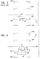
- Fig. 4 illustrates a HUD display 40 with a runway symbol 64 in front of the aircraft, and the aircraft is in a slightly nose low position as indicated by the aircraft indicator 62.
- the runway symbol 64 includes a threshold symbol 66, two runway side symbols 68, 70, a runway end symbol 72, and a runway centerline symbol 74.
- the size, shape, and outline of the runway 64 will be determined by data on the runway stored in memory 42, and generated by the symbol generator 43.
- Similar aircraft landing location symbols can be generated for heliports, seaports, taxiways, etc.
- the memory 42 illustrated contains data pertaining to the length, width, angle, and other characteristics of the runway. Based upon this data and the information obtained from the present invention relating to where the aircraft is with respect to the aircraft landing location, and accurate portrayal of the runway, and the centerline, can be created by the symbol generator.
- the prior art infra-red sensor technology produces a similar, but more complex and expensive device to that illustrated in Fig. 4 (the prior art device is not illustrated).
- the runway area in the prior art device is of a different appearance than the surrounding (grass covered) areas since infra-red systems interact with the two areas differently. It can be difficult, however, to distinguish the runway from other roads, taxiways, etc. of the surrounding area.
- One advantage of the prior art infrared technology compared to the Fig. 4 device is that other aircraft, trucks, etc. can be detected in the prior art device, wherein the Fig. 4 embodiment will not illustrate obstructions on the runway.
- Fig. 4 image appears much more similar to the other types of graphics which are used, and understood, by pilots in most of the cockpit instrumentation (especially in HUD and HDD displays) than the prior art infra-red image. It can be difficult to detect the runway centerline or edges in the prior art embodiment. Also, there is only one runway which will be illustrated on the Fig. 4 present invention embodiment wherein the prior art infra-red embodiment will illustrate everything which is made of a material which appears to an IR sensor similarly to runways.
- Fig. 4 illustrates how a perspective image of the runway surface can be drawn similarly to what the pilot would observe from his field of view (FOV).
- the FOV can be defined as the pilots cone of vision originating at the pilots eyes. If the pilot had a 360 degree FOV and the aircraft was always level, only the first three elements of the state vector (V1, V2 and V3) would be necessary to determine the proper image of the runway. However, the pilot's view is limited by the fuselage, the cockpit, and the pilot also limits the FOV to that information which is directly ahead for landing and take off operations.
- the actual useful image for the pilot is one that is found by determining the intersection of the cone representing the FOV with the eye of the pilot that is oriented along the V5 element of the state vector (attitude of the aircraft) and the surface of the earth.
- the image that is created in the HUD is a function of both the position of the aircraft (in the Cartesian coordinate system) and the attitude of the aircraft.
- bank angle information can be obtained to further partition the imaginary cone, which represents the FOV of the pilot.
- the projection of the cone will likely encompass the aircraft landing location. If it does not, the view that is presented to the pilot in the HUD will not include the runway, which is informative by the conspicuous lack of the aircraft landing location. Under these circumstance the pilot will have to look elsewhere to determine where the aircraft landing location is.
- the pilot will be presented with what practically represents a real time display of the aircraft landing location. Given the accuracy of typical landing systems, and the associated signals which are generated therefrom, it is within the realm of current design to provide a HUD which provides a location of the aircraft landing location which is within a meter of the actual aircraft landing location (in all dimensions). Essentially, the pilot will be presented with a synthetic image of the aircraft landing location. Such an image would appear similar to those found in aircraft simulators or video games, which in both cases have been shown to be completely satisfactory for fully controlling an aircraft in take off and landing operations.
- the three dimensional image of the aircraft landing location must be derived from purely the electronic information provided by the signals transmitted from the antennas associated with the landing system. This is accomplished through the following formulation of aircraft flight equations and laws, which is non-standard and non-linear, and is formulated to have a one on one correspondence with the required elements of the state vector that is suitable for producing a useful image on the HUD. In this manner, the most efficient means can be applied to determine the elements of the state vector by relying on the signals which are generated from the ground portions of the landing systems into space.
- An external transmitter (which may be ground based for ILS, MLS, etc. or satellite based for GPS, etc.) communicates with an airborne receiver to continually provide updates of the above information which may be used for the following components:
- the above components are presently available in commercial and military aviation products which provide navigation to the aircraft, but is not displayed to the pilot in an accurate, real time display.
- Each of these components communicates digitally (or can be made to communicate digitally) with existing, tested; and approved avionics according to one of two standards for such components.
- the applicable standards exist as MIL-STD-1553B interface, which is recognized for all modern military aircraft.
- the applicable standard is ARINC 429. With each interface the standards define a digital interface bus and associated codes for all the necessary information, as well as information that may specifically need to be defined, in order that avionics devices can be made to communicate with each other. Therefore, the protocol and hardware interface requirements for military and commercial aviation already exist.
- the interface for commercial and military HUDS and HDDs is the above described symbol generator, which also operates over a 1553 interface (military) or an ARINC 429 bus interface for commercial aircraft. Over this digital interface, this device receives commands to create specific images (which have been predefined by the symbol generator) on a HUD or HDD display.
- specific images which have been predefined by the symbol generator
- HUD or HDD display There exists a large variety of standard images which may be created by the symbol generator including a straight line, a circle, a rectangle, etc, with specific coordinates in the field of view.
- HUD or HDD real time three dimensional image
- Present HUD or HDD uses a more or less standard straight line segment draw operations, as is well known in any graphics display program.
- mapping from the measurement set ⁇ S1, S2 ⁇ to the state vector is nonlinear, but it is continually differentiable and hence may be approximated as linear in the neighborhood that is sufficiently close to the true solution of the system.
- S1 is associated with measurements made at time epoch 1 and S2 is associated with measurements made at a consecutive epoch, which is a function of the sample rate of the aircraft receiver. If DGPS were not utilized, r and P would be equivalent.
- each individual location in space which receives signals from the landing system of the present invention must each have a characteristic set of signal which are received at that point.
- the above equations are applicable for each observation epoch t i .
- g4(V1, V2, V3, t1) (V1-Xa)2 + (V2-Ya)2 + (V3-Za)2 - r2
- g5(V1, V2, V3, t1) -cos2 ⁇ (V2-Ya)2 + sin2 ⁇ (V1-Xa)2 + sin2 ⁇ (V3-Za)2
- g6(V1, V2, V3, t1) -sin2 ⁇ (V1-X f )2 - sin2 ⁇ (V2-Yf)2 + cos2 ⁇ (V3-Z f )2
- Data products that result from a flight of an aircraft will be a continuous stream of MLS, DME, and DGPS measurements which will be partitioned into two sets: S1 and S2, on an alternate basis. By relying on these measurements, which constitutes a stochastic process, it will now be shown how to derive an estimate of the state that is suitable for three dimensional imaging.
- a suitable value of Omega (the chosen one is based on a survey of the literature and conservative estimates) is chosen, resulting in the following covariance matrix for the observations associated with, and including the DGPS (in the form of slant range) into the measurement set:
- the raw MLS measurements are alternated between S1 and S2, which is a means for artificially creating the minimal set of 6 measurements in order to estimate the state, assuming that the bank angle is fixed (and known).
- the bank angle is available from the avionics of conventional aircraft.
- a typical covarience matrix of the difference between the true trajectory and the one resulting from the above measurements is as follows: To refine the state estimates, the state estimator using the nonlinear estimator of the next section is applied.
- the raw measurement from S1 to S2 are processed to produce a "raw" state estimator which is optimized by passing it through the nonlinear filter of this section.
- the advantage of using the non-linear filter is that it is typically simpler to process then the prior art linear filter, and the applicable equations are better known and more accepted. Therefore, the non-linear filter will be able to perform more complex computations at a nearer to real time rate then the linear ones.
- the following non-linear estimation algorithm is applied to the state estimation problem associated with the stated aircraft problem in order to assure that accurate information is utilized when developing an accurate three dimensional image in the HUD.
Landscapes
- Engineering & Computer Science (AREA)
- Aviation & Aerospace Engineering (AREA)
- Physics & Mathematics (AREA)
- General Physics & Mathematics (AREA)
- Radar, Positioning & Navigation (AREA)
- Remote Sensing (AREA)
- Automation & Control Theory (AREA)
- Traffic Control Systems (AREA)
- Navigation (AREA)
- Position Fixing By Use Of Radio Waves (AREA)
Applications Claiming Priority (2)
| Application Number | Priority Date | Filing Date | Title |
|---|---|---|---|
| US191871 | 1980-09-29 | ||
| US19187194A | 1994-02-04 | 1994-02-04 |
Publications (1)
| Publication Number | Publication Date |
|---|---|
| EP0670566A2 true EP0670566A2 (fr) | 1995-09-06 |
Family
ID=22707241
Family Applications (1)
| Application Number | Title | Priority Date | Filing Date |
|---|---|---|---|
| EP95101090A Withdrawn EP0670566A2 (fr) | 1994-02-04 | 1995-01-26 | Système hybride synthétiques d'atterrissage pour aéronef |
Country Status (3)
| Country | Link |
|---|---|
| EP (1) | EP0670566A2 (fr) |
| JP (1) | JPH07272200A (fr) |
| CA (1) | CA2136570A1 (fr) |
Cited By (17)
| Publication number | Priority date | Publication date | Assignee | Title |
|---|---|---|---|---|
| WO1997026553A1 (fr) * | 1996-01-19 | 1997-07-24 | Sextant Avionique | Systeme d'aide au pilotage d'aeronefs a l'aide d'un viseur tete haute |
| FR2857330A1 (fr) * | 2003-07-07 | 2005-01-14 | Daniel Albert Lemascon | Atterrissage par satellites avec visualisation du plan d'approche de l'avion |
| US7612716B2 (en) | 1999-03-05 | 2009-11-03 | Era Systems Corporation | Correlation of flight track data with other data sources |
| US7667647B2 (en) | 1999-03-05 | 2010-02-23 | Era Systems Corporation | Extension of aircraft tracking and positive identification from movement areas into non-movement areas |
| US7739167B2 (en) | 1999-03-05 | 2010-06-15 | Era Systems Corporation | Automated management of airport revenues |
| US7777675B2 (en) | 1999-03-05 | 2010-08-17 | Era Systems Corporation | Deployable passive broadband aircraft tracking |
| US7782256B2 (en) | 1999-03-05 | 2010-08-24 | Era Systems Corporation | Enhanced passive coherent location techniques to track and identify UAVs, UCAVs, MAVs, and other objects |
| US7889133B2 (en) | 1999-03-05 | 2011-02-15 | Itt Manufacturing Enterprises, Inc. | Multilateration enhancements for noise and operations management |
| US7908077B2 (en) | 2003-06-10 | 2011-03-15 | Itt Manufacturing Enterprises, Inc. | Land use compatibility planning software |
| US7965227B2 (en) | 2006-05-08 | 2011-06-21 | Era Systems, Inc. | Aircraft tracking using low cost tagging as a discriminator |
| US8072382B2 (en) | 1999-03-05 | 2011-12-06 | Sra International, Inc. | Method and apparatus for ADS-B validation, active and passive multilateration, and elliptical surveillance |
| WO2011159412A1 (fr) | 2010-06-15 | 2011-12-22 | The Boeing Company | Système de pistes en perspective |
| US8203486B1 (en) | 1999-03-05 | 2012-06-19 | Omnipol A.S. | Transmitter independent techniques to extend the performance of passive coherent location |
| US8446321B2 (en) | 1999-03-05 | 2013-05-21 | Omnipol A.S. | Deployable intelligence and tracking system for homeland security and search and rescue |
| EP2188179A4 (fr) * | 2007-08-17 | 2016-08-03 | Sikorsky Aircraft Corp | Approche stabilisée vers un point en environnement visuel dégradé |
| CN116816208A (zh) * | 2023-08-30 | 2023-09-29 | 同致电子科技(厦门)有限公司 | 一种车门雷达静止障碍物识别增强方法 |
| CN120065686A (zh) * | 2025-04-27 | 2025-05-30 | 杭州智元研究院有限公司 | 基于飞控的安全容灾系统及方法 |
Families Citing this family (2)
| Publication number | Priority date | Publication date | Assignee | Title |
|---|---|---|---|---|
| KR101276254B1 (ko) * | 2011-12-15 | 2013-06-20 | 경상대학교산학협력단 | 항공기의 상황 대응 시스템 |
| US9522742B2 (en) * | 2014-03-18 | 2016-12-20 | The Boeing Company | Short landing warning |
-
1994
- 1994-11-24 CA CA002136570A patent/CA2136570A1/fr not_active Abandoned
-
1995
- 1995-01-26 EP EP95101090A patent/EP0670566A2/fr not_active Withdrawn
- 1995-01-30 JP JP7012836A patent/JPH07272200A/ja active Pending
Cited By (20)
| Publication number | Priority date | Publication date | Assignee | Title |
|---|---|---|---|---|
| WO1997026553A1 (fr) * | 1996-01-19 | 1997-07-24 | Sextant Avionique | Systeme d'aide au pilotage d'aeronefs a l'aide d'un viseur tete haute |
| FR2743892A1 (fr) * | 1996-01-19 | 1997-07-25 | Sextant Avionique | Systeme d'aide au pilotage d'aeronefs a l'aide d'un viseur tete haute |
| US7777675B2 (en) | 1999-03-05 | 2010-08-17 | Era Systems Corporation | Deployable passive broadband aircraft tracking |
| US7612716B2 (en) | 1999-03-05 | 2009-11-03 | Era Systems Corporation | Correlation of flight track data with other data sources |
| US7667647B2 (en) | 1999-03-05 | 2010-02-23 | Era Systems Corporation | Extension of aircraft tracking and positive identification from movement areas into non-movement areas |
| US7739167B2 (en) | 1999-03-05 | 2010-06-15 | Era Systems Corporation | Automated management of airport revenues |
| US8203486B1 (en) | 1999-03-05 | 2012-06-19 | Omnipol A.S. | Transmitter independent techniques to extend the performance of passive coherent location |
| US7782256B2 (en) | 1999-03-05 | 2010-08-24 | Era Systems Corporation | Enhanced passive coherent location techniques to track and identify UAVs, UCAVs, MAVs, and other objects |
| US7889133B2 (en) | 1999-03-05 | 2011-02-15 | Itt Manufacturing Enterprises, Inc. | Multilateration enhancements for noise and operations management |
| US8072382B2 (en) | 1999-03-05 | 2011-12-06 | Sra International, Inc. | Method and apparatus for ADS-B validation, active and passive multilateration, and elliptical surveillance |
| US8446321B2 (en) | 1999-03-05 | 2013-05-21 | Omnipol A.S. | Deployable intelligence and tracking system for homeland security and search and rescue |
| US7908077B2 (en) | 2003-06-10 | 2011-03-15 | Itt Manufacturing Enterprises, Inc. | Land use compatibility planning software |
| FR2857330A1 (fr) * | 2003-07-07 | 2005-01-14 | Daniel Albert Lemascon | Atterrissage par satellites avec visualisation du plan d'approche de l'avion |
| US7965227B2 (en) | 2006-05-08 | 2011-06-21 | Era Systems, Inc. | Aircraft tracking using low cost tagging as a discriminator |
| EP2188179A4 (fr) * | 2007-08-17 | 2016-08-03 | Sikorsky Aircraft Corp | Approche stabilisée vers un point en environnement visuel dégradé |
| WO2011159412A1 (fr) | 2010-06-15 | 2011-12-22 | The Boeing Company | Système de pistes en perspective |
| US8711007B2 (en) | 2010-06-15 | 2014-04-29 | The Boeing Company | Perspective runway system |
| CN116816208A (zh) * | 2023-08-30 | 2023-09-29 | 同致电子科技(厦门)有限公司 | 一种车门雷达静止障碍物识别增强方法 |
| CN116816208B (zh) * | 2023-08-30 | 2023-12-22 | 同致电子科技(厦门)有限公司 | 一种车门雷达静止障碍物识别增强方法 |
| CN120065686A (zh) * | 2025-04-27 | 2025-05-30 | 杭州智元研究院有限公司 | 基于飞控的安全容灾系统及方法 |
Also Published As
| Publication number | Publication date |
|---|---|
| CA2136570A1 (fr) | 1995-08-05 |
| JPH07272200A (ja) | 1995-10-20 |
Similar Documents
| Publication | Publication Date | Title |
|---|---|---|
| EP0670566A2 (fr) | Système hybride synthétiques d'atterrissage pour aéronef | |
| US6076042A (en) | Altitude sparse aircraft display | |
| US6208284B1 (en) | Radar augmented TCAS | |
| EP1476720B1 (fr) | Appareil pour l'affichage d'information terrain et meteorologie sur un seul ecran d'affichage | |
| US7920943B2 (en) | Precision approach guidance system and associated method | |
| US8755954B1 (en) | System and method for generating alert signals in a terrain awareness and warning system of an aircraft using a forward-looking radar system | |
| US7295901B1 (en) | System and method for indicating a position of an aircraft to a user | |
| RU2134911C1 (ru) | Система предупреждения столкновения летательных аппаратов при летных испытаниях | |
| US11587449B2 (en) | Systems and methods for guiding a vertical takeoff and landing vehicle to an emergency landing zone | |
| JP2001513240A (ja) | 空中衝突及び地勢衝突の危険を航空機に表示する装置 | |
| JPH02500390A (ja) | 航空監視方法及びその方法を用いるシステム | |
| CN113739799B (zh) | 全球定位拒止的导航 | |
| EP4032813B1 (fr) | Systèmes de vision informatique et procédés d'aide à la décision d'atterrissage | |
| EP3869486A1 (fr) | Systèmes et procédés permettant de guider un véhicule à décollage et atterrissage vertical vers une zone d'atterrissage d'urgence | |
| EP2037216B1 (fr) | Système et procédé pour l'affichage d'un terrain numérisé | |
| US7218245B2 (en) | Head-down aircraft attitude display and method for displaying schematic and terrain data symbology | |
| EP1775553B1 (fr) | Viseur d'attitude d'aéronef tête basse centré hybride et procédé de calcul de la limite d'angle de dérive affichée | |
| US11105930B1 (en) | Self contained satellite-navigation-based method and micro system for real-time relative-position determination | |
| US12541029B2 (en) | RNP navigation without GNSS | |
| US12394325B2 (en) | Optimized weather and threat depiction based on aircraft flight plan | |
| Ferguson et al. | Synthetic vision/enhanced vision system implementation | |
| McGee et al. | Automatic helical rotorcraft descent and landing using a microwave landing system | |
| Casserly et al. | Operation of current navigation aids and future prospects | |
| Berkstresser | Trends in transport aircraft avionics | |
| Adams | " ZERO ZERO" ROTORCRAFT CERTIFICATION ISSUES |
Legal Events
| Date | Code | Title | Description |
|---|---|---|---|
| PUAI | Public reference made under article 153(3) epc to a published international application that has entered the european phase |
Free format text: ORIGINAL CODE: 0009012 |
|
| AK | Designated contracting states |
Kind code of ref document: A2 Designated state(s): DE ES FR GB IT SE |
|
| STAA | Information on the status of an ep patent application or granted ep patent |
Free format text: STATUS: THE APPLICATION HAS BEEN WITHDRAWN |
|
| 18W | Application withdrawn |
Withdrawal date: 19951211 |
|
| R18W | Application withdrawn (corrected) |
Effective date: 19951211 |