EP0670580A1 - Interface de tige flexible d'un disjoncteur - Google Patents
Interface de tige flexible d'un disjoncteur Download PDFInfo
- Publication number
- EP0670580A1 EP0670580A1 EP95102679A EP95102679A EP0670580A1 EP 0670580 A1 EP0670580 A1 EP 0670580A1 EP 95102679 A EP95102679 A EP 95102679A EP 95102679 A EP95102679 A EP 95102679A EP 0670580 A1 EP0670580 A1 EP 0670580A1
- Authority
- EP
- European Patent Office
- Prior art keywords
- handle
- switching mechanism
- flexible shaft
- attachment means
- handle attachment
- Prior art date
- Legal status (The legal status is an assumption and is not a legal conclusion. Google has not performed a legal analysis and makes no representation as to the accuracy of the status listed.)
- Granted
Links
- 238000009434 installation Methods 0.000 description 4
- 230000004048 modification Effects 0.000 description 4
- 238000012986 modification Methods 0.000 description 4
- 238000005553 drilling Methods 0.000 description 1
Images


Classifications
-
- H—ELECTRICITY
- H01—ELECTRIC ELEMENTS
- H01H—ELECTRIC SWITCHES; RELAYS; SELECTORS; EMERGENCY PROTECTIVE DEVICES
- H01H3/00—Mechanisms for operating contacts
- H01H3/32—Driving mechanisms, i.e. for transmitting driving force to the contacts
- H01H3/36—Driving mechanisms, i.e. for transmitting driving force to the contacts using belt, chain, or cord
-
- H—ELECTRICITY
- H01—ELECTRIC ELEMENTS
- H01H—ELECTRIC SWITCHES; RELAYS; SELECTORS; EMERGENCY PROTECTIVE DEVICES
- H01H71/00—Details of the protective switches or relays covered by groups H01H73/00 - H01H83/00
- H01H71/10—Operating or release mechanisms
- H01H71/50—Manual reset mechanisms which may be also used for manual release
- H01H71/52—Manual reset mechanisms which may be also used for manual release actuated by lever
Definitions
- This invention is directed to an interface between a flexible shaft and a circuit interrupting device, and more particularly to such an interface between a linearly movable rod of the flexible shaft and a handle of a circuit breaker.
- Circuit interrupters e.g., circuit switching devices, circuit breakers, etc.
- circuit breakers are generally old and well-known in the art. Examples of circuit breakers are disclosed in U.S. Patent Numbers 4,489,295; 4,638,277; 4,656,444 and 4,679,018. Such circuit breakers are used to protect electrical circuitry from damage due to an overcurrent condition, such as an overload and relatively high level short circuit condition.
- Molded case circuit breakers include at least one pair of separable contacts which may be operated either manually by way of a handle disposed on the outside of the case or automatically in response to an overcurrent condition.
- a common type of circuit switching device has a front face with a manual handle which may be arcuately operated between an on position and an off position.
- a common type of circuit breaker has a similar handle which is connected to movable contacts through a spring powered, over center toggle device which trips the contacts open and moves the handle to an intermediate trip position in response to certain overcurrent conditions.
- a fourth, reset position which is beyond the off position and opposite from the on position, is used to reset a trip mechanism of the circuit breaker following a trip condition.
- circuit interrupters are commonly mounted behind a panel or behind a door in a cabinet.
- the handles of the circuit interrupters are not directly accessible by the operator.
- a remote handle mechanism is mounted to the opposite side of the panel or door and a mechanical linkage is used to interconnect the remote handle mechanism with the circuit interrupter handle.
- a flexible shaft replaces the mechanical linkage.
- the flexible shaft includes a fixed outer jacket having a linearly movable core; a bulkhead hub for securing the fixed outer jacket on one side of the bulkhead and for providing a swivel sleeve on the other side; and a linearly movable rod, which exits an end of the sleeve opposite from the bulkhead and which is attached to the movable core within the sleeve.
- the remote handle mechanism drives one end of the core of the flexible shaft in a linear push-pull manner.
- the rod at the other end of the flexible shaft is used to drive a sliding operating mechanism in a similar linear push-pull fashion.
- the sliding operating mechanism is mounted on the front face of the circuit interrupter and has a hole for inserting the circuit interrupter handle therethrough. In turn, the linear motion of the sliding operating mechanism is used to simulate the arcuate motion of the circuit interrupter handle.
- Operability of the remote handle mechanism with the flexible shaft and the sliding operating mechanism is limited in several ways.
- Second, the force applied by the sliding operating mechanism to the circuit interrupter handle is generally angled away from a tangent to the arcuate rotation path of the handle. Thus, only a fraction of the force provided by the flexible shaft is applied to rotate the handle.
- a handle extension having a base and two arms is attached to the handle for extending a length of the handle and for rotating the handle between the on position and the off position.
- a generally U-shaped bracket having a base and two arms is pivotally mounted by the arms of the bracket to the arms of the handle extension.
- the base of the U-shaped bracket is attached to a linearly movable end of the flexible shaft.
- a bulkhead hub of the flexible shaft is fixedly mounted to a face of the circuit interrupter by a mounting bracket.
- a pulling motion of the flexible shaft pulls the bracket which rotates the pivotally mounted handle extension and the attached handle toward the off position.
- a pushing motion of the flexible shaft pushes the bracket which rotates the handle extension and the handle toward the on position.
- Either a pulling or a pushing force, applied by the flexible shaft to the bracket is generally in the same linear direction as a longitudinal axis of the arms of the bracket.
- the entire force of the flexible shaft is generally applied to the bracket.
- the longitudinal axis of the arms of the pivotally mounted bracket, and hence the force applied to the bracket is generally tangential to the arcuate path of the handle between the on and the off positions. Therefore, the entire force of the flexible shaft and the bracket is generally applied to efficiently rotate the handle.
- the pivot point of the arms of the bracket and the arms of the handle extension is extended beyond an end of the handle, the additional leverage associated with the extended length reduces the force required to move the handle between the on and the off positions.
- the base of the handle extension has a mounting tab which rests on an end of the handle. In this manner, the handle extension is self-positioned on the handle.
- the base further has a mounting clamp, which is secured to the base, at either end of the clamp, by mounting hardware.
- the base, mounting tab and clamp firmly grasp the handle without requiring any modification of the handle (e.g., drilling a mounting hole).
- an alternative handle extension is provided for circuit interrupters having a handle with a mounting hole.
- This alternative handle extension is similar in operation to the above described handle extension.
- the alternative handle extension does not have a handle mounting clamp or a handle mounting tab. Instead, the handle is secured by mounting hardware to a mounting hole in a base of the alternative handle extension.
- a cross-pin located between the arms of the alternative handle extension, relieves stress on the handle and the handle mounting hardware whenever the flexible shaft applies a pulling force.
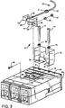
- a switching mechanism 10 interfaces a flexible shaft 20 to a circuit breaker 30.
- the circuit breaker 30 has a handle 32 and a front face 34.
- the handle 32 is arcuately movable between an off position (as shown in Figure 1) and an opposite on position (as shown in Figure 3).
- the handle 32 has a lower surface 36 (facing away in Figure 1) for pushing the handle 32 toward the on position and an opposite upper surface 38 for pulling the handle 32 toward the off position. It being understood that the invention is applicable to additional handle positions (e.g., trip and reset) as well as other types of circuit interrupters (e.g., a circuit switching device).
- the flexible shaft 20 includes a fixed outer jacket 22 having an inner movable core 19 (shown in shadow in Figure 2).
- a bulkhead hub 21 secures the fixed outer jacket 22 on one side of the hub 21 and provides a swivel sleeve 29 on the other side.
- the bulkhead hub 21 includes two outer hex nuts 27 and two inner washers 28 for fixedly securing the flexible shaft 20 to a baseplate 70.
- the swivel sleeve 29 connects a sleeve 25 to the bulkhead hub 21 in order that a longitudinal axis of the sleeve 25 may rotate approximately 8 degrees with respect to a longitudinal axis of the hub 21.
- the sleeve 25 also encloses the inner movable core 19 which is routed through the outer jacket 22 and the bulkhead hub 21.
- a remote handle mechanism (not shown) drives the other end (not shown) of the core in a linear push-pull manner.
- a threaded end 24 of the rod 26 includes a hex nut 23 and is secured to a bracket mechanism 60 in a manner to be described below.
- a baseplate 70 is formed in a generally inverted-U-shape and has an upper U-shaped mounting depression 71 and two lower feet 78 which each have a mounting hole 79.
- the baseplate 70 is attached to two mounting holes 72 in the face 34 of the circuit breaker 30 using two screws 74 and two lock washers 76.
- the flexible shaft 20 rests within the depression 71 at a center 16 of the hub 21.
- the baseplate 70 is secured to the hub 21 between the washers 28 by the hex nuts 27.
- a generally U-shaped handle extension 40 having a base 42 and two L-shaped arms 44,46 is attached to the handle 32.
- the extension 40 extends a length of the handle 32 and is utilized to rotate the handle 32 between the on position and the off position.
- a mounting tab 43 which is perpendicular to the base 42, rests on top of the handle 32. This positions a length of the handle 32 within the base 42 and allows the handle extension 40 to be self-positioned on the handle 32.
- the base 42 faces the lower surface 36 of the handle 32.
- a rectangular clamp 41 having two holes 45a on either end is attached to the base 42 at corresponding holes 45b using screws 47, lock washers 48 and hex nuts 49. In the exemplary embodiment, the clamp 41 and the base 42 firmly grasp the handle 32 without requiring a handle mounting hole 33 (see Figure 3).
- a bracket 60 is generally U-shaped and includes a base 62 and two arms 64,66 which each have pivot holes 51a.
- the bracket 60 is pivotally mounted at the pivot holes 51a of the arms 64,66 to corresponding pivot holes 51b in the arms 44,46, respectively, using rivets 65, hardened sleeves 67 and washers 69.
- the threaded end 24 of the rod 26 is passed through a hole 63 in the base 62 and is connected to the base 62 using opposing hex nuts 23,68.
- the hex nuts 23,68 are adjusted to properly position the rod 26, in order to accurately translate linear positions of the rod 26 to the corresponding on and off positions of the handle 32.
- a pulling motion of the rod 26 pulls the bracket 60 which rotates the handle extension 40 and the handle 32 toward the off position.
- a pushing motion of the rod 26 pushes the bracket 60 which rotates the handle extension 40 and the handle 32 in the opposite direction toward the on position.
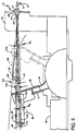
- either a pulling or pushing force, applied by the rod 26 to the bracket 60 is generally in the same linear direction as a longitudinal axis of the arms 64 (see Figure 2) and 66 of the bracket 60.
- An angle of a longitudinal axis of the rod 26 with respect to a longitudinal axis of the bulkhead hub 21 of the flexible shaft 20 ranges between ⁇ A and ⁇ B , which are limited to an absolute value of approximately 8 degrees in the exemplary embodiment.
- at least 99% (or the cosine of 8 degrees) of the pulling or pushing force of the flexible shaft 20 is applied to the handle extension 60.
- an angle of a longitudinal axis of the arms 64,66 with respect to a tangent to an arcuate path of the handle 32 ranges between ⁇ B and ⁇ C , which are limited to an absolute value of approximately 30 degrees in the exemplary embodiment.
- ⁇ B and ⁇ C which are limited to an absolute value of approximately 30 degrees in the exemplary embodiment.
- FIG. 3-4 an alternative embodiment of the invention is illustrated for handle 32 having a mounting hole 33.
- An alternative handle extension 50 is similar in operation to the above described handle extension 40 (see Figures 1-2).
- the handle extension 50 has a base 52 and two L-shaped arms 54,56, which each have a pivot hole 51b.
- the handle extension 50 does not utilize a handle mounting clamp 41 or a handle mounting tab 43 (see Figures 1-2).
- the handle 32 is secured to the handle extension 50 by a screw 39, a lock washer 35 and a hex nut 37 to a mounting hole 58 in the base 52.
- a cross-pin 59 is attached between the arms 54,56 of the handle extension 50 adjacent the upper surface 38 of the handle 32. Whenever the handle 32 is moved from the exemplary on position to the off position, some of the associated opening force is provided by the cross-pin 59. Thus, the cross-pin 59 relieves any excessive stress of the screw 39 at mounting hole 33.
Landscapes
- Breakers (AREA)
- Coupling Device And Connection With Printed Circuit (AREA)
Applications Claiming Priority (2)
| Application Number | Priority Date | Filing Date | Title |
|---|---|---|---|
| US08/203,900 US5428196A (en) | 1994-03-01 | 1994-03-01 | Flexible shaft interface for circuit interrupter |
| US203900 | 1994-03-01 |
Publications (2)
| Publication Number | Publication Date |
|---|---|
| EP0670580A1 true EP0670580A1 (fr) | 1995-09-06 |
| EP0670580B1 EP0670580B1 (fr) | 1999-04-14 |
Family
ID=22755770
Family Applications (1)
| Application Number | Title | Priority Date | Filing Date |
|---|---|---|---|
| EP95102679A Expired - Lifetime EP0670580B1 (fr) | 1994-03-01 | 1995-02-24 | Interface de tige flexible d'un disjoncteur |
Country Status (5)
| Country | Link |
|---|---|
| US (1) | US5428196A (fr) |
| EP (1) | EP0670580B1 (fr) |
| JP (1) | JPH07312163A (fr) |
| CA (1) | CA2143561C (fr) |
| DE (1) | DE69508993T2 (fr) |
Families Citing this family (15)
| Publication number | Priority date | Publication date | Assignee | Title |
|---|---|---|---|---|
| US5726401A (en) * | 1996-03-29 | 1998-03-10 | Siemens Energy & Automation, Inc. | Cable/crossbar interlock system for circuit breakers |
| US5814777A (en) * | 1996-03-29 | 1998-09-29 | Siemens Energy & Automation,Inc. | Cable interlock system for circuit breakers |
| US5973279A (en) * | 1997-12-12 | 1999-10-26 | Eaton Corporation | Stabilizer for a circuit breaker handle mechanism |
| US6072132A (en) * | 1999-09-28 | 2000-06-06 | Eaton Corporation | Apparatus for mounting a motor operator on a circuit |
| US6710697B1 (en) * | 2002-11-18 | 2004-03-23 | Rockwell Automation Technologies, Inc. | Flexible cable operated fuse switch |
| US6706984B1 (en) * | 2002-11-20 | 2004-03-16 | S. Chase Turner | Device for remote activation of control box buttons |
| US8178806B2 (en) * | 2009-04-17 | 2012-05-15 | General Electric Company | Device for mounting an accessory device to a circuit breaker |
| US9530576B2 (en) * | 2013-04-10 | 2016-12-27 | Savannah River Nuclear Solutions, Llc | Device for remote operation of electrical disconnect |
| US9218920B2 (en) * | 2013-11-12 | 2015-12-22 | Rockwell Automation Technologies, Inc. | Flexible cable assembly providing local lockout |
| US9177732B2 (en) | 2013-11-12 | 2015-11-03 | Rockwell Automation Technologies, Inc. | Flexible cable assembly with improved manufacturability |
| US9177731B2 (en) | 2013-11-12 | 2015-11-03 | Rockwell Automation Technologies, Inc. | Flexible cable assembly for high-power switch gear |
| USD731441S1 (en) | 2014-03-20 | 2015-06-09 | Rockwell Automation Technologies, Inc. | Cable actuated switch operating device |
| USD727855S1 (en) | 2014-03-20 | 2015-04-28 | Rockwell Automation Technologies, Inc. | Cable actuated switch operating device |
| GB2543810A (en) | 2015-10-29 | 2017-05-03 | Eaton Ind Mfg Gmbh | Operating mechanism for a toggle switch handle, particularly of a circuit breaker |
| CN111524759B (zh) * | 2017-11-21 | 2022-09-23 | 乾友科技有限公司 | 一种断路器自动分合闸操作装置及其断路器 |
Citations (4)
| Publication number | Priority date | Publication date | Assignee | Title |
|---|---|---|---|---|
| US3939725A (en) * | 1973-10-25 | 1976-02-24 | Maynard Braverman | Remote switch actuating device |
| EP0176066A2 (fr) * | 1984-09-28 | 1986-04-02 | Siemens Aktiengesellschaft | Dispositif pour l'actionnement d'un disjoncteur électrique de puissance |
| EP0183931A2 (fr) * | 1984-12-06 | 1986-06-11 | Siemens Aktiengesellschaft | Dispositif de commande à distance d'un interrupteur électrique ou d'un appareil semblable |
| US5272296A (en) * | 1990-08-02 | 1993-12-21 | General Electric Company | Molded case circuit breaker variable actuator mechanism |
Family Cites Families (2)
| Publication number | Priority date | Publication date | Assignee | Title |
|---|---|---|---|---|
| US5270505A (en) * | 1989-12-18 | 1993-12-14 | Joseph Magiera | Remote controlled switch/receptacle |
| US5319168A (en) * | 1993-01-04 | 1994-06-07 | Westinghouse Electric Corp. | Circuit breaker retractable handle mechanism |
-
1994
- 1994-03-01 US US08/203,900 patent/US5428196A/en not_active Expired - Lifetime
-
1995
- 1995-02-24 DE DE69508993T patent/DE69508993T2/de not_active Expired - Lifetime
- 1995-02-24 EP EP95102679A patent/EP0670580B1/fr not_active Expired - Lifetime
- 1995-02-28 CA CA002143561A patent/CA2143561C/fr not_active Expired - Lifetime
- 1995-03-01 JP JP7068762A patent/JPH07312163A/ja active Pending
Patent Citations (4)
| Publication number | Priority date | Publication date | Assignee | Title |
|---|---|---|---|---|
| US3939725A (en) * | 1973-10-25 | 1976-02-24 | Maynard Braverman | Remote switch actuating device |
| EP0176066A2 (fr) * | 1984-09-28 | 1986-04-02 | Siemens Aktiengesellschaft | Dispositif pour l'actionnement d'un disjoncteur électrique de puissance |
| EP0183931A2 (fr) * | 1984-12-06 | 1986-06-11 | Siemens Aktiengesellschaft | Dispositif de commande à distance d'un interrupteur électrique ou d'un appareil semblable |
| US5272296A (en) * | 1990-08-02 | 1993-12-21 | General Electric Company | Molded case circuit breaker variable actuator mechanism |
Also Published As
| Publication number | Publication date |
|---|---|
| US5428196A (en) | 1995-06-27 |
| CA2143561A1 (fr) | 1995-09-02 |
| JPH07312163A (ja) | 1995-11-28 |
| CA2143561C (fr) | 2002-10-01 |
| EP0670580B1 (fr) | 1999-04-14 |
| DE69508993T2 (de) | 1999-12-02 |
| DE69508993D1 (de) | 1999-05-20 |
Similar Documents
| Publication | Publication Date | Title |
|---|---|---|
| US5428196A (en) | Flexible shaft interface for circuit interrupter | |
| US5493084A (en) | Door release for circuit interrupter rotary handle mechanism | |
| CA1265832A (fr) | Systeme de telecommande de materiel electrique | |
| AU2006201945B2 (en) | Handle attachment, assist mechanism therefor, and electrical switching apparatus employing the same | |
| AU661690B2 (en) | Lockable rotary handle operator for circuit breaker | |
| US5288958A (en) | Lockable remote rotary handle operator for circuit breakers | |
| KR100695635B1 (ko) | 3개의 위치를 갖는 기계적 가시화 수단을 구비하는 스위치기어 장치 | |
| EP0923095B1 (fr) | Stabilisateur pour un mécanisme de levier disjoncteur | |
| US7361857B2 (en) | External operating handle mechanism for mold cased circuit breaker | |
| US7238903B2 (en) | Electrical switching apparatus operating mechanism with operating member therefor, and enclosure assembly employing the same | |
| US5710399A (en) | Electronic trip unit conversion kit for high ampere-rated circuit breakers | |
| US6326871B1 (en) | Switchgear unit of a switching device and a coupled leading auxiliary switch | |
| US6642463B1 (en) | Circuit breaker remote actuator with fulcrum member to assist assembly and associated method | |
| US5701111A (en) | Electronic trip unit conversion kit for high ampere-rated circuit breakers | |
| US7019240B2 (en) | Electrical switching apparatus interface assembly and operating handle attachment therefor | |
| US5272296A (en) | Molded case circuit breaker variable actuator mechanism | |
| US5700985A (en) | Interlock latch for electrical operator | |
| US20020158734A1 (en) | Handle operating mechanism of circuit breaker | |
| US8022319B2 (en) | Handle operator linkage with sealing means | |
| US20020104747A1 (en) | Motor operator for electric power switch and electric power switches incorporating the same | |
| US3244827A (en) | Switch actuating mechanism | |
| KR200208218Y1 (ko) | 배선용 차단기의 경보겸용 보조스위치 | |
| CN217280490U (zh) | 开关柜用联锁机构及具有其的开关柜 | |
| JPS6367726B2 (fr) | ||
| US20060132270A1 (en) | Double-lever mechanism, trip actuator assembly and electrical switching apparatus employing the same |
Legal Events
| Date | Code | Title | Description |
|---|---|---|---|
| PUAI | Public reference made under article 153(3) epc to a published international application that has entered the european phase |
Free format text: ORIGINAL CODE: 0009012 |
|
| AK | Designated contracting states |
Kind code of ref document: A1 Designated state(s): DE GB IT SE |
|
| 17P | Request for examination filed |
Effective date: 19960226 |
|
| 17Q | First examination report despatched |
Effective date: 19970131 |
|
| PLBQ | Unpublished change to opponent data |
Free format text: ORIGINAL CODE: EPIDOS OPPO |
|
| PLBQ | Unpublished change to opponent data |
Free format text: ORIGINAL CODE: EPIDOS OPPO |
|
| GRAG | Despatch of communication of intention to grant |
Free format text: ORIGINAL CODE: EPIDOS AGRA |
|
| GRAG | Despatch of communication of intention to grant |
Free format text: ORIGINAL CODE: EPIDOS AGRA |
|
| GRAH | Despatch of communication of intention to grant a patent |
Free format text: ORIGINAL CODE: EPIDOS IGRA |
|
| GRAH | Despatch of communication of intention to grant a patent |
Free format text: ORIGINAL CODE: EPIDOS IGRA |
|
| GRAA | (expected) grant |
Free format text: ORIGINAL CODE: 0009210 |
|
| AK | Designated contracting states |
Kind code of ref document: B1 Designated state(s): DE GB IT SE |
|
| REF | Corresponds to: |
Ref document number: 69508993 Country of ref document: DE Date of ref document: 19990520 |
|
| PLBE | No opposition filed within time limit |
Free format text: ORIGINAL CODE: 0009261 |
|
| STAA | Information on the status of an ep patent application or granted ep patent |
Free format text: STATUS: NO OPPOSITION FILED WITHIN TIME LIMIT |
|
| 26N | No opposition filed | ||
| REG | Reference to a national code |
Ref country code: GB Ref legal event code: IF02 |
|
| PGFP | Annual fee paid to national office [announced via postgrant information from national office to epo] |
Ref country code: SE Payment date: 20020201 Year of fee payment: 8 |
|
| PG25 | Lapsed in a contracting state [announced via postgrant information from national office to epo] |
Ref country code: SE Free format text: LAPSE BECAUSE OF NON-PAYMENT OF DUE FEES Effective date: 20030225 |
|
| EUG | Se: european patent has lapsed | ||
| PGFP | Annual fee paid to national office [announced via postgrant information from national office to epo] |
Ref country code: GB Payment date: 20070105 Year of fee payment: 13 |
|
| PGFP | Annual fee paid to national office [announced via postgrant information from national office to epo] |
Ref country code: IT Payment date: 20070525 Year of fee payment: 13 |
|
| GBPC | Gb: european patent ceased through non-payment of renewal fee |
Effective date: 20080224 |
|
| PG25 | Lapsed in a contracting state [announced via postgrant information from national office to epo] |
Ref country code: GB Free format text: LAPSE BECAUSE OF NON-PAYMENT OF DUE FEES Effective date: 20080224 |
|
| PG25 | Lapsed in a contracting state [announced via postgrant information from national office to epo] |
Ref country code: IT Free format text: LAPSE BECAUSE OF NON-PAYMENT OF DUE FEES Effective date: 20080224 |
|
| PGFP | Annual fee paid to national office [announced via postgrant information from national office to epo] |
Ref country code: DE Payment date: 20140228 Year of fee payment: 20 |
|
| REG | Reference to a national code |
Ref country code: DE Ref legal event code: R071 Ref document number: 69508993 Country of ref document: DE |