EP0670794B1 - Soupape de regulation de pression de fluide - Google Patents
Soupape de regulation de pression de fluide Download PDFInfo
- Publication number
- EP0670794B1 EP0670794B1 EP19940901589 EP94901589A EP0670794B1 EP 0670794 B1 EP0670794 B1 EP 0670794B1 EP 19940901589 EP19940901589 EP 19940901589 EP 94901589 A EP94901589 A EP 94901589A EP 0670794 B1 EP0670794 B1 EP 0670794B1
- Authority
- EP
- European Patent Office
- Prior art keywords
- valve
- piston
- check valve
- port
- fluid pressure
- Prior art date
- Legal status (The legal status is an assumption and is not a legal conclusion. Google has not performed a legal analysis and makes no representation as to the accuracy of the status listed.)
- Expired - Lifetime
Links
- 239000012530 fluid Substances 0.000 title claims abstract description 26
- 238000007789 sealing Methods 0.000 claims description 5
- 230000008961 swelling Effects 0.000 description 4
- 239000000356 contaminant Substances 0.000 description 3
- 230000000694 effects Effects 0.000 description 3
- 238000004140 cleaning Methods 0.000 description 2
- 238000011109 contamination Methods 0.000 description 2
- 230000007257 malfunction Effects 0.000 description 2
- 230000009471 action Effects 0.000 description 1
- 230000007246 mechanism Effects 0.000 description 1
- 239000002184 metal Substances 0.000 description 1
- 230000004044 response Effects 0.000 description 1
Images

Classifications
-
- B—PERFORMING OPERATIONS; TRANSPORTING
- B60—VEHICLES IN GENERAL
- B60T—VEHICLE BRAKE CONTROL SYSTEMS OR PARTS THEREOF; BRAKE CONTROL SYSTEMS OR PARTS THEREOF, IN GENERAL; ARRANGEMENT OF BRAKING ELEMENTS ON VEHICLES IN GENERAL; PORTABLE DEVICES FOR PREVENTING UNWANTED MOVEMENT OF VEHICLES; VEHICLE MODIFICATIONS TO FACILITATE COOLING OF BRAKES
- B60T15/00—Construction arrangement, or operation of valves incorporated in power brake systems and not covered by groups B60T11/00 or B60T13/00
- B60T15/02—Application and release valves
- B60T15/18—Triple or other relay valves which allow step-wise application or release and which are actuated by brake-pipe pressure variation to connect brake cylinders or equivalent to compressed air or vacuum source or atmosphere
- B60T15/20—Triple or other relay valves which allow step-wise application or release and which are actuated by brake-pipe pressure variation to connect brake cylinders or equivalent to compressed air or vacuum source or atmosphere controlled by two fluid pressures
-
- B—PERFORMING OPERATIONS; TRANSPORTING
- B60—VEHICLES IN GENERAL
- B60T—VEHICLE BRAKE CONTROL SYSTEMS OR PARTS THEREOF; BRAKE CONTROL SYSTEMS OR PARTS THEREOF, IN GENERAL; ARRANGEMENT OF BRAKING ELEMENTS ON VEHICLES IN GENERAL; PORTABLE DEVICES FOR PREVENTING UNWANTED MOVEMENT OF VEHICLES; VEHICLE MODIFICATIONS TO FACILITATE COOLING OF BRAKES
- B60T13/00—Transmitting braking action from initiating means to ultimate brake actuator with power assistance or drive; Brake systems incorporating such transmitting means, e.g. air-pressure brake systems
- B60T13/10—Transmitting braking action from initiating means to ultimate brake actuator with power assistance or drive; Brake systems incorporating such transmitting means, e.g. air-pressure brake systems with fluid assistance, drive, or release
- B60T13/24—Transmitting braking action from initiating means to ultimate brake actuator with power assistance or drive; Brake systems incorporating such transmitting means, e.g. air-pressure brake systems with fluid assistance, drive, or release the fluid being gaseous
- B60T13/26—Compressed-air systems
- B60T13/261—Compressed-air systems systems with both indirect application and application by springs or weights and released by compressed air
- B60T13/265—Compressed-air systems systems with both indirect application and application by springs or weights and released by compressed air dependent systems, e.g. trailer systems
-
- Y—GENERAL TAGGING OF NEW TECHNOLOGICAL DEVELOPMENTS; GENERAL TAGGING OF CROSS-SECTIONAL TECHNOLOGIES SPANNING OVER SEVERAL SECTIONS OF THE IPC; TECHNICAL SUBJECTS COVERED BY FORMER USPC CROSS-REFERENCE ART COLLECTIONS [XRACs] AND DIGESTS
- Y10—TECHNICAL SUBJECTS COVERED BY FORMER USPC
- Y10T—TECHNICAL SUBJECTS COVERED BY FORMER US CLASSIFICATION
- Y10T137/00—Fluid handling
- Y10T137/8593—Systems
- Y10T137/86919—Sequentially closing and opening alternately seating flow controllers
Definitions
- This invention relates to a fluid pressure control valve.
- the valve according to the present invention is designed for use as a component of a trailer air brake systems. Reservoirs on such trailer brake systems are charged through a valve such as disclosed in SE,B 349,989 and Gba, A 1,459,686. In such brake systems, the reservoirs are being charged during a service brake application until the pressure in the reservoirs attains a predetermined pressure level, whereupon the service actuation is released.
- a relatively simple valve member is supported on a guide pin between a valve guide and a pressure responsive piston.
- the guide pin extends into an exhaust passage that extends through the piston, thereby automatically cleaning the exhaust passage during normal operation of the valve.
- a valve guide engages a surface of a valve member opposite the surface engaged by the piston, and extends toward a check valve element which controls communication through the inlet to the valve mechanism, thereby also serving as a spring guide for the spring controlling the check valve element and also as a stop for limiting movement of the check valve element.
- a valve which is substantially smaller than prior art valves, and is resistant to contamination, since the smallest passage is continually cleaned by the guide pin and the rubber valve member is guided by the guide pin instead of an outside diameter, so that swelling of the rubber will not affect valve performance.
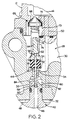
- the housing 12 defines a chamber 28 therewithin which is divided into an inlet section 30 and an outlet section 32 by valve seat 34.
- Outlet section 32 is stepped to define a smaller diameter portion 36 and a larger diameter portion 38.
- a stepped piston 40 has corresponding smaller and larger diameter sections that are slidably and sealably received within the smaller diameter portion 36 and larger diameter portion 38 of the section 32 of the chamber 28.
- a spring 42 yieldably urges the piston 40 upwardly, viewing the Figure, such that upper end 44 of the piston 40 extends through the valve seat 34.
- An exhaust passage 46 extends through the stepped piston 40 and communicates with the exhaust port 24.
- a shoulder 48 is defined between the larger and smaller diameter portions of the piston 40, and defines-a fluid pressure responsive surface which is communicated directly to inlet port 14 through passage 50.
- the upper end 44 of the piston 40 terminates in a valve seat which is sealingly engaged by end 52 of a valve member 54 to prevent communication from section 30 of chamber 28 into the exhaust passage 46.
- the valve member 54 is mounted on a guide pin 56, one end 58 of which is slidably received in reduced diameter portion 60 of the passage 46.
- the opposite end 62 of the guide pin 56 is formed integrally with a coaxial valve guide 64. Communication of fluid pressure into the section 30 from the inlet port 14 is controlled by a check valve assembly generally indicated by the numeral 66.
- the portion 80 of outlet section 32 defined between the circumferentially extending surface 82 on the smaller diameter portion of the piston 40 and the valve seat 34 is communicated to service brake actuator 22 through outlet port 20.
- the portion 80 is communicated to the outlet port 20 through passage 84 and a check valve assembly generally indicated by the numeral 86.
- the check valve assembly 86 includes a hat-shaped valve element 88 and a spring 90 which urges the valve element 88 against the seating area 92.
- center portion of valve element 88 moves to sealingly engage valve seat 93.
- pressure in passage 84 increases by an amount sufficient to deflect the spring 90, pressure flows to the outlet port 20.
- pressure at outlet port 20 exhausts through exhaust port 94 to atmosphere.
- piston 40 moves downwardly, viewing the Figures, thereby permitting the end 52 of valve element 54 to sealingly engage the valve seat 34 in response to the action of the spring 74 and fluid pressure in the inlet section 30.
- the reservoirs 18, however, will continue to be charged until the reservoirs reach full system pressure due to the fact that the outlet opening 16 continues to communicate pressure to the reservoirs until the pressure in the reservoir attains system pressure, whereupon the check valve assembly 66 closes to prevent communication out of the reservoirs to the inlet port 14 in case the pressure at inlet port 14 is vented.
- Pressure at port 14 is vented, for example, when the trailer supply line breaks or is disconnected. When this occurs, pressure in section 32 is also vented, permitting the spring 42 to urge the piston 40 upwardly viewing the Figures to again establish communication between opening 16 and passage 84. Fluid pressure deflects valve 88 to communicate to service brake application effecting means to effect a trailer service brake application.
- the various components of the valve 10 are specifically designed to minimize cost, resist contamination, and to provide a valve of minimum size.
- the guide pin 56 is slidably received in the smallest portion 60 of the exhaust passage 46. Because of the relative movements between the piston 40 and the guide pin 56 during the normal operation of the valve, the exhaust passage 46 is self-cleaning. Furthermore, the guide pin 56 mounts the valve element 54, instead of the valve element 54 being guided on outer diameter as in prior art devices. Accordingly, the operation of the valve 10 is not sensitive to swelling of the valve element 54, so that the valve element 54 need not be a bonded element and may be made significantly smaller than would otherwise be necessary.
- the valve guide 64 performs multiple functions including limiting and controlling movement of the valve element 54, providing a seat for the spring 74, and providing a stop for the check valve element 68.
Landscapes
- Engineering & Computer Science (AREA)
- Transportation (AREA)
- Mechanical Engineering (AREA)
- Physics & Mathematics (AREA)
- Fluid Mechanics (AREA)
- Valves And Accessory Devices For Braking Systems (AREA)
- Check Valves (AREA)
Abstract
Claims (5)
- Soupape sensible à la pression de fluide comprenant un logement (12) ayant un orifice d'entrée (14), un orifice de sortie (20), et un orifice d'échappement (24), ledit logement (12) définissant une chambre (28) en son sein mettant lesdits orifices en communication les uns avec les autres, ladite chambre (28) étant divisée par une paroi en une section d'entrée (30) et une section de sortie (32), ladite paroi ayant un siège de soupape (34) par lequel ladite section d'entrée (30) est mise en communication avec ladite section de sortie (32), un piston (40) étant monté à coulissement dans ladite section de sortie (32) et un organe de soupape (54) situé dans ladite section d'entrée (30) et étant connecté audit piston (40) pour réguler la communication de fluide depuis ladite section d'entrée (30) jusqu'audit orifice de sortie (20) en vue d'une distribution vers un système, ledit piston réagissant à la présence de fluide audit orifice d'entrée (14) en se déplaçant à l'intérieur de ladite section de sortie pour mettre du fluide en communication avec ledit système à partir dudit orifice d'entrée (14) jusqu'à l'orifice de sortie (20) et à partir de l'orifice de sortie (20) jusqu'à l'orifice d'échappement (24), ledit piston étant caractérisé en ce qu'il a une extrémité (44) qui s'étend à travers ledit siège de soupape (34) et qui porte à coulissement une broche de guidage (56), ledit organe de soupape (54) étant monté sur ladite broche de guidage (56) et guidé par celle-ci et étant également séparé de la paroi définissant ladite chambre (28), ledit piston (40) étant comprimé de manière élastique par un ressort (42) vers une position maintenant ledit organe de soupape (54) séparé dudit siège de soupape (34) pour permettre une communication ininterrompue entre ladite section d'entrée (30) et ledit orifice de sortie (20), ledit piston (40) ayant une surface sensible à la pression de fluide (48) réagissant à la présence de pression de fluide audit orifice d'entrée (14) pour engendrer une force qui surmonte la force dudit ressort (42) pour déplacer initialement ledit piston (40) et ladite extrémité (44) par rapport audit siège de soupape (34) et permettre audit organe de soupape (54) d'engager de manière étanche ledit siège de soupape (34) et, par la suite, écarter ledit piston (40) et ladite extrémité (44) dudit organe de soupape (54) pour permettre l'évacuation de fluide hors dudit système au moyen desdits orifice de sortie (20) et orifice d'évacuation (24).
- Soupape sensible à la pression de fluide selon la revendication 1, caractérisée en outre en ce que ledit piston (40) définit un passage d'évacuation (46) s'étendant à travers lui communiquant avec ledit orifice d'évacuation (24), ledit passage d'évacuation (46) mettant ledit orifice de sortie (20) en communication avec ledit orifice d'évacuation (24) après que ledit piston (40) s'écarte dudit organe de soupape (54).
- Soupape sensible à la pression de fluide selon la revendication 2, caractérisée en outre en ce que ladite broche de guidage (56) est reçue à coulissement dans ledit passage d'évacuation (46).
- Soupape sensible à la pression de fluide selon la revendication 1, caractérisée en outre en ce qu'une soupape de retenue (66) régule la communication à travers ledit orifice d'entrée (14) pour permettre la communication dans ladite chambre (28), ladite soupape de retenue (66) comportant un élément de soupape de retenue (68) substantiellement coaxial audit piston (40) et un ressort de soupape de retenue (74) comprimant de manière élastique ledit élément de soupape de retenue (68) en engagement étanche avec un siège de soupape de retenue porté par ledit logement (12), ledit ressort de soupape de retenue (74) s'étendant entre un épaulement sur un guide de soupape (64) et ledit élément de soupape de retenue (68), ce par quoi ledit guide de soupape (64) oriente et guide ledit ressort de soupape de retenue (74).
- Soupape sensible à la pression de fluide selon la revendication 4, caractérisée en outre en ce que ledit guide de soupape (64) se termine par une extrémité disposée à une distance prédéterminée dudit élément de soupape de retenue (68), ladite extrémité engageant ledit élément de soupape de retenue (68) pour limiter à une distance prédéterminée la déviation de l'élément de soupape de retenue (68).
Applications Claiming Priority (3)
| Application Number | Priority Date | Filing Date | Title |
|---|---|---|---|
| US07/984,409 US5346291A (en) | 1992-12-02 | 1992-12-02 | Fluid pressure control valve with valve member mounted on guide pin slidably carried by piston |
| US984409 | 1992-12-02 | ||
| PCT/US1993/011204 WO1994012379A1 (fr) | 1992-12-02 | 1993-11-18 | Soupape de regulation de pression de fluide |
Publications (2)
| Publication Number | Publication Date |
|---|---|
| EP0670794A1 EP0670794A1 (fr) | 1995-09-13 |
| EP0670794B1 true EP0670794B1 (fr) | 1997-01-15 |
Family
ID=25530537
Family Applications (1)
| Application Number | Title | Priority Date | Filing Date |
|---|---|---|---|
| EP19940901589 Expired - Lifetime EP0670794B1 (fr) | 1992-12-02 | 1993-11-18 | Soupape de regulation de pression de fluide |
Country Status (5)
| Country | Link |
|---|---|
| US (1) | US5346291A (fr) |
| EP (1) | EP0670794B1 (fr) |
| JP (1) | JPH08503907A (fr) |
| DE (1) | DE69307546T2 (fr) |
| WO (1) | WO1994012379A1 (fr) |
Families Citing this family (6)
| Publication number | Priority date | Publication date | Assignee | Title |
|---|---|---|---|---|
| US5762094A (en) * | 1997-04-11 | 1998-06-09 | Alliedsignal Truck Brake Systems Co. | Automatic valve drain |
| US6079795A (en) | 1998-06-08 | 2000-06-27 | Westinghouse Air Brake Technologies Corporation | Load proportional brake cylinder pressure limiting system |
| US6217635B1 (en) | 1998-11-09 | 2001-04-17 | Fantom Technologies Inc. | Method and apparatus for concentrating a gas using a single stage adsorption chamber |
| US6179391B1 (en) | 1999-02-01 | 2001-01-30 | Allliedsignal Truck Brake Systems Company | Relay valve with integral biased double check valve |
| US7556322B2 (en) * | 2004-01-27 | 2009-07-07 | Wabtec Holding Corp. | Graduated release/proportioning valve |
| US8083293B2 (en) * | 2009-05-11 | 2011-12-27 | Wabtec Holding Corp. | Empty/load brake control device with multi-stage sensing |
Family Cites Families (21)
| Publication number | Priority date | Publication date | Assignee | Title |
|---|---|---|---|---|
| US3001831A (en) * | 1959-08-26 | 1961-09-26 | Kelsey Hayes Co | Tractor-trailer brake system |
| US3169804A (en) * | 1963-04-23 | 1965-02-16 | Wagner Electric Corp | Control valve |
| GB1034828A (en) * | 1963-07-17 | 1966-07-06 | Girling Ltd | Improvements in control valves for air braking systems |
| US3464742A (en) * | 1968-03-29 | 1969-09-02 | Wagner Electric Corp | Control valve |
| US3479096A (en) * | 1968-05-31 | 1969-11-18 | Wagner Electric Corp | Control valve |
| US3460872A (en) * | 1968-06-07 | 1969-08-12 | Westinghouse Air Brake Co | Variable load valve device |
| US3504946A (en) * | 1968-10-03 | 1970-04-07 | Bendix Westinghouse Automotive | Spring brake control valve |
| US3549208A (en) * | 1968-10-29 | 1970-12-22 | Wagner Electric Corp | Control valve |
| US3744848A (en) * | 1971-09-07 | 1973-07-10 | Wagner Electric Corp | Control valve |
| US3837361A (en) * | 1971-10-26 | 1974-09-24 | Eaton Corp | Emergency control valve |
| CH568175A5 (fr) * | 1973-07-06 | 1975-10-31 | Oerlikon Buehrle Ag | |
| US3857614A (en) * | 1973-10-12 | 1974-12-31 | Midland Ross Corp | Air brake antiskid control |
| JPS5228194B2 (fr) * | 1973-12-06 | 1977-07-25 | ||
| US3920045A (en) * | 1974-01-22 | 1975-11-18 | Berg Manufacturing Co | Relay emergency valve |
| US3971596A (en) * | 1974-12-26 | 1976-07-27 | Wagner Electric Corporation | Electro-pneumatic air brake valve and system compatible with a skid control system |
| US4453779A (en) * | 1982-02-18 | 1984-06-12 | American Standard Inc. | Adjustable variable load control valve device |
| FR2545572B1 (fr) * | 1983-05-04 | 1986-05-02 | Outillage Air Comprime | Regulateur pneumatique de pression |
| US4502351A (en) * | 1983-08-08 | 1985-03-05 | Gates Guy W | Third accumulator check valve |
| IT207058Z2 (it) * | 1986-04-02 | 1987-11-02 | Magneti Marelli Spa | Valvola pneumatica per impianti di frenatura |
| US4924901A (en) * | 1988-10-19 | 1990-05-15 | Fluid Jet International Inc. | In line valve |
| JPH02154873A (ja) * | 1988-12-05 | 1990-06-14 | Takashi Kimura | 空圧シリンダ用切換弁 |
-
1992
- 1992-12-02 US US07/984,409 patent/US5346291A/en not_active Expired - Fee Related
-
1993
- 1993-11-18 EP EP19940901589 patent/EP0670794B1/fr not_active Expired - Lifetime
- 1993-11-18 JP JP51325494A patent/JPH08503907A/ja active Pending
- 1993-11-18 DE DE69307546T patent/DE69307546T2/de not_active Expired - Fee Related
- 1993-11-18 WO PCT/US1993/011204 patent/WO1994012379A1/fr not_active Ceased
Also Published As
| Publication number | Publication date |
|---|---|
| EP0670794A1 (fr) | 1995-09-13 |
| DE69307546D1 (de) | 1997-02-27 |
| WO1994012379A1 (fr) | 1994-06-09 |
| JPH08503907A (ja) | 1996-04-30 |
| DE69307546T2 (de) | 1997-05-15 |
| US5346291A (en) | 1994-09-13 |
Similar Documents
| Publication | Publication Date | Title |
|---|---|---|
| US6247764B1 (en) | Full function valve for heavy duty semi-trailer brake systems | |
| CA2405336C (fr) | Soupape combinee d'inversion, de relais ou de detente rapide | |
| CA2286215C (fr) | Purge de valve automatique | |
| US4080004A (en) | Service and emergency trailer valve | |
| US4025126A (en) | Brake control valve device with movable control reservoir charging valve | |
| US5346291A (en) | Fluid pressure control valve with valve member mounted on guide pin slidably carried by piston | |
| PL149279B1 (en) | Relay valve | |
| US4043605A (en) | Emergency portion for a brake control valve | |
| US4042281A (en) | Service and emergency trailer valve | |
| US4163585A (en) | Service and emergency trailer valve | |
| US4068902A (en) | Adaptive braking modulator with electrically activated relay valve | |
| US4145090A (en) | Continual quick service valve device | |
| US4653811A (en) | Relay valve device | |
| EP0184681B1 (fr) | Valve de commande de freinage | |
| JP4348053B2 (ja) | 牽引車両のブレーキをコントロールするための特にトラクタユニットのエアブレーキシステムに使用するバルブユニット | |
| EP0234042B2 (fr) | Valve de freinage à deux circuits | |
| US4175792A (en) | Continual quick service valve device | |
| US4113319A (en) | Emergency portion for a brake control valve | |
| CA1278598C (fr) | Clapet protecteur pour systeme de frein de secours a ressort | |
| KR960012399B1 (ko) | 2중 면적 2차 피스톤이 있는 압력분배식 브레이크 밸브 | |
| WO2005000654A1 (fr) | Valve d'inversion pour systeme de frein a air comprime de vehicule a moteur | |
| WO1992016400A1 (fr) | Procede et appareil de commande du niveau de pression dans un systeme de freinage adaptatif a air comprime | |
| CN115556735A (zh) | 自调式的继动阀 | |
| WO2024082082A1 (fr) | Dispositif pneumatique ayant un clapet de non-retour et une voie d'échappement supplémentaire comportant un dispositif de scellement étanche | |
| US5295512A (en) | Fluid control spool valve |
Legal Events
| Date | Code | Title | Description |
|---|---|---|---|
| PUAI | Public reference made under article 153(3) epc to a published international application that has entered the european phase |
Free format text: ORIGINAL CODE: 0009012 |
|
| 17P | Request for examination filed |
Effective date: 19950526 |
|
| AK | Designated contracting states |
Kind code of ref document: A1 Designated state(s): DE FR GB IT |
|
| GRAG | Despatch of communication of intention to grant |
Free format text: ORIGINAL CODE: EPIDOS AGRA |
|
| 17Q | First examination report despatched |
Effective date: 19960125 |
|
| GRAH | Despatch of communication of intention to grant a patent |
Free format text: ORIGINAL CODE: EPIDOS IGRA |
|
| GRAH | Despatch of communication of intention to grant a patent |
Free format text: ORIGINAL CODE: EPIDOS IGRA |
|
| GRAA | (expected) grant |
Free format text: ORIGINAL CODE: 0009210 |
|
| AK | Designated contracting states |
Kind code of ref document: B1 Designated state(s): DE FR GB IT |
|
| ITF | It: translation for a ep patent filed | ||
| ET | Fr: translation filed | ||
| REF | Corresponds to: |
Ref document number: 69307546 Country of ref document: DE Date of ref document: 19970227 |
|
| PLBE | No opposition filed within time limit |
Free format text: ORIGINAL CODE: 0009261 |
|
| STAA | Information on the status of an ep patent application or granted ep patent |
Free format text: STATUS: NO OPPOSITION FILED WITHIN TIME LIMIT |
|
| 26N | No opposition filed | ||
| REG | Reference to a national code |
Ref country code: GB Ref legal event code: IF02 |
|
| REG | Reference to a national code |
Ref country code: GB Ref legal event code: 732E |
|
| PGFP | Annual fee paid to national office [announced via postgrant information from national office to epo] |
Ref country code: FR Payment date: 20031202 Year of fee payment: 11 |
|
| PGFP | Annual fee paid to national office [announced via postgrant information from national office to epo] |
Ref country code: GB Payment date: 20031203 Year of fee payment: 11 |
|
| PGFP | Annual fee paid to national office [announced via postgrant information from national office to epo] |
Ref country code: DE Payment date: 20031231 Year of fee payment: 11 |
|
| PG25 | Lapsed in a contracting state [announced via postgrant information from national office to epo] |
Ref country code: GB Free format text: LAPSE BECAUSE OF NON-PAYMENT OF DUE FEES Effective date: 20041118 |
|
| PG25 | Lapsed in a contracting state [announced via postgrant information from national office to epo] |
Ref country code: DE Free format text: LAPSE BECAUSE OF NON-PAYMENT OF DUE FEES Effective date: 20050601 |
|
| GBPC | Gb: european patent ceased through non-payment of renewal fee |
Effective date: 20041118 |
|
| PG25 | Lapsed in a contracting state [announced via postgrant information from national office to epo] |
Ref country code: FR Free format text: LAPSE BECAUSE OF NON-PAYMENT OF DUE FEES Effective date: 20050729 |
|
| REG | Reference to a national code |
Ref country code: FR Ref legal event code: ST |
|
| PG25 | Lapsed in a contracting state [announced via postgrant information from national office to epo] |
Ref country code: IT Free format text: LAPSE BECAUSE OF NON-PAYMENT OF DUE FEES;WARNING: LAPSES OF ITALIAN PATENTS WITH EFFECTIVE DATE BEFORE 2007 MAY HAVE OCCURRED AT ANY TIME BEFORE 2007. THE CORRECT EFFECTIVE DATE MAY BE DIFFERENT FROM THE ONE RECORDED. Effective date: 20051118 |