EP0671032B1 - Kodierung mit modulation, fehlerkontrolle, gewichtung und bitzuordnung - Google Patents
Kodierung mit modulation, fehlerkontrolle, gewichtung und bitzuordnung Download PDFInfo
- Publication number
- EP0671032B1 EP0671032B1 EP94902473A EP94902473A EP0671032B1 EP 0671032 B1 EP0671032 B1 EP 0671032B1 EP 94902473 A EP94902473 A EP 94902473A EP 94902473 A EP94902473 A EP 94902473A EP 0671032 B1 EP0671032 B1 EP 0671032B1
- Authority
- EP
- European Patent Office
- Prior art keywords
- bit
- vectors
- code
- speech
- error control
- Prior art date
- Legal status (The legal status is an assumption and is not a legal conclusion. Google has not performed a legal analysis and makes no representation as to the accuracy of the status listed.)
- Expired - Lifetime
Links
- 239000013598 vector Substances 0.000 claims description 113
- 238000000034 method Methods 0.000 claims description 60
- 230000005284 excitation Effects 0.000 claims description 19
- 230000003595 spectral effect Effects 0.000 description 54
- 238000010586 diagram Methods 0.000 description 16
- 238000004891 communication Methods 0.000 description 14
- 230000015556 catabolic process Effects 0.000 description 9
- 238000006731 degradation reaction Methods 0.000 description 9
- 238000009499 grossing Methods 0.000 description 9
- 230000015572 biosynthetic process Effects 0.000 description 8
- 238000003786 synthesis reaction Methods 0.000 description 8
- 230000006870 function Effects 0.000 description 7
- 230000008569 process Effects 0.000 description 7
- 230000003044 adaptive effect Effects 0.000 description 6
- 238000012937 correction Methods 0.000 description 6
- 238000012913 prioritisation Methods 0.000 description 5
- 238000013459 approach Methods 0.000 description 4
- 230000001419 dependent effect Effects 0.000 description 4
- 230000007246 mechanism Effects 0.000 description 4
- 238000013139 quantization Methods 0.000 description 4
- 230000035945 sensitivity Effects 0.000 description 4
- 230000005540 biological transmission Effects 0.000 description 3
- 238000001514 detection method Methods 0.000 description 3
- 230000000737 periodic effect Effects 0.000 description 3
- 230000009471 action Effects 0.000 description 2
- 230000008859 change Effects 0.000 description 2
- 230000007423 decrease Effects 0.000 description 2
- 230000000694 effects Effects 0.000 description 2
- 238000010295 mobile communication Methods 0.000 description 2
- 238000012545 processing Methods 0.000 description 2
- 238000007792 addition Methods 0.000 description 1
- 230000008901 benefit Effects 0.000 description 1
- 230000001413 cellular effect Effects 0.000 description 1
- 238000006243 chemical reaction Methods 0.000 description 1
- 230000006835 compression Effects 0.000 description 1
- 238000007906 compression Methods 0.000 description 1
- 238000010276 construction Methods 0.000 description 1
- 230000003247 decreasing effect Effects 0.000 description 1
- 230000002708 enhancing effect Effects 0.000 description 1
- 238000000695 excitation spectrum Methods 0.000 description 1
- 238000005562 fading Methods 0.000 description 1
- 230000014509 gene expression Effects 0.000 description 1
- 239000011159 matrix material Substances 0.000 description 1
- 239000000203 mixture Substances 0.000 description 1
- 230000008520 organization Effects 0.000 description 1
- 230000008447 perception Effects 0.000 description 1
- 230000004044 response Effects 0.000 description 1
- 238000005070 sampling Methods 0.000 description 1
- 238000000926 separation method Methods 0.000 description 1
- 238000000638 solvent extraction Methods 0.000 description 1
- 238000001228 spectrum Methods 0.000 description 1
- 238000010561 standard procedure Methods 0.000 description 1
- 230000002194 synthesizing effect Effects 0.000 description 1
- 230000009897 systematic effect Effects 0.000 description 1
- 230000009466 transformation Effects 0.000 description 1
- 238000000844 transformation Methods 0.000 description 1
Images







Classifications
-
- H—ELECTRICITY
- H04—ELECTRIC COMMUNICATION TECHNIQUE
- H04L—TRANSMISSION OF DIGITAL INFORMATION, e.g. TELEGRAPHIC COMMUNICATION
- H04L1/00—Arrangements for detecting or preventing errors in the information received
- H04L1/004—Arrangements for detecting or preventing errors in the information received by using forward error control
- H04L1/0056—Systems characterized by the type of code used
- H04L1/0057—Block codes
- H04L1/0058—Block-coded modulation
-
- G—PHYSICS
- G10—MUSICAL INSTRUMENTS; ACOUSTICS
- G10L—SPEECH ANALYSIS TECHNIQUES OR SPEECH SYNTHESIS; SPEECH RECOGNITION; SPEECH OR VOICE PROCESSING TECHNIQUES; SPEECH OR AUDIO CODING OR DECODING
- G10L19/00—Speech or audio signals analysis-synthesis techniques for redundancy reduction, e.g. in vocoders; Coding or decoding of speech or audio signals, using source filter models or psychoacoustic analysis
- G10L19/002—Dynamic bit allocation
-
- G—PHYSICS
- G10—MUSICAL INSTRUMENTS; ACOUSTICS
- G10L—SPEECH ANALYSIS TECHNIQUES OR SPEECH SYNTHESIS; SPEECH RECOGNITION; SPEECH OR VOICE PROCESSING TECHNIQUES; SPEECH OR AUDIO CODING OR DECODING
- G10L19/00—Speech or audio signals analysis-synthesis techniques for redundancy reduction, e.g. in vocoders; Coding or decoding of speech or audio signals, using source filter models or psychoacoustic analysis
- G10L19/005—Correction of errors induced by the transmission channel, if related to the coding algorithm
-
- G—PHYSICS
- G10—MUSICAL INSTRUMENTS; ACOUSTICS
- G10L—SPEECH ANALYSIS TECHNIQUES OR SPEECH SYNTHESIS; SPEECH RECOGNITION; SPEECH OR VOICE PROCESSING TECHNIQUES; SPEECH OR AUDIO CODING OR DECODING
- G10L19/00—Speech or audio signals analysis-synthesis techniques for redundancy reduction, e.g. in vocoders; Coding or decoding of speech or audio signals, using source filter models or psychoacoustic analysis
- G10L19/04—Speech or audio signals analysis-synthesis techniques for redundancy reduction, e.g. in vocoders; Coding or decoding of speech or audio signals, using source filter models or psychoacoustic analysis using predictive techniques
- G10L19/06—Determination or coding of the spectral characteristics, e.g. of the short-term prediction coefficients
-
- H—ELECTRICITY
- H03—ELECTRONIC CIRCUITRY
- H03M—CODING; DECODING; CODE CONVERSION IN GENERAL
- H03M13/00—Coding, decoding or code conversion, for error detection or error correction; Coding theory basic assumptions; Coding bounds; Error probability evaluation methods; Channel models; Simulation or testing of codes
-
- H—ELECTRICITY
- H03—ELECTRONIC CIRCUITRY
- H03M—CODING; DECODING; CODE CONVERSION IN GENERAL
- H03M13/00—Coding, decoding or code conversion, for error detection or error correction; Coding theory basic assumptions; Coding bounds; Error probability evaluation methods; Channel models; Simulation or testing of codes
- H03M13/03—Error detection or forward error correction by redundancy in data representation, i.e. code words containing more digits than the source words
- H03M13/05—Error detection or forward error correction by redundancy in data representation, i.e. code words containing more digits than the source words using block codes, i.e. a predetermined number of check bits joined to a predetermined number of information bits
- H03M13/13—Linear codes
- H03M13/15—Cyclic codes, i.e. cyclic shifts of codewords produce other codewords, e.g. codes defined by a generator polynomial, Bose-Chaudhuri-Hocquenghem [BCH] codes
- H03M13/1505—Golay Codes
-
- H—ELECTRICITY
- H03—ELECTRONIC CIRCUITRY
- H03M—CODING; DECODING; CODE CONVERSION IN GENERAL
- H03M13/00—Coding, decoding or code conversion, for error detection or error correction; Coding theory basic assumptions; Coding bounds; Error probability evaluation methods; Channel models; Simulation or testing of codes
- H03M13/03—Error detection or forward error correction by redundancy in data representation, i.e. code words containing more digits than the source words
- H03M13/05—Error detection or forward error correction by redundancy in data representation, i.e. code words containing more digits than the source words using block codes, i.e. a predetermined number of check bits joined to a predetermined number of information bits
- H03M13/13—Linear codes
- H03M13/19—Single error correction without using particular properties of the cyclic codes, e.g. Hamming codes, extended or generalised Hamming codes
-
- H—ELECTRICITY
- H03—ELECTRONIC CIRCUITRY
- H03M—CODING; DECODING; CODE CONVERSION IN GENERAL
- H03M13/00—Coding, decoding or code conversion, for error detection or error correction; Coding theory basic assumptions; Coding bounds; Error probability evaluation methods; Channel models; Simulation or testing of codes
- H03M13/29—Coding, decoding or code conversion, for error detection or error correction; Coding theory basic assumptions; Coding bounds; Error probability evaluation methods; Channel models; Simulation or testing of codes combining two or more codes or code structures, e.g. product codes, generalised product codes, concatenated codes, inner and outer codes
-
- H—ELECTRICITY
- H03—ELECTRONIC CIRCUITRY
- H03M—CODING; DECODING; CODE CONVERSION IN GENERAL
- H03M13/00—Coding, decoding or code conversion, for error detection or error correction; Coding theory basic assumptions; Coding bounds; Error probability evaluation methods; Channel models; Simulation or testing of codes
- H03M13/29—Coding, decoding or code conversion, for error detection or error correction; Coding theory basic assumptions; Coding bounds; Error probability evaluation methods; Channel models; Simulation or testing of codes combining two or more codes or code structures, e.g. product codes, generalised product codes, concatenated codes, inner and outer codes
- H03M13/2903—Methods and arrangements specifically for encoding, e.g. parallel encoding of a plurality of constituent codes
-
- H—ELECTRICITY
- H03—ELECTRONIC CIRCUITRY
- H03M—CODING; DECODING; CODE CONVERSION IN GENERAL
- H03M13/00—Coding, decoding or code conversion, for error detection or error correction; Coding theory basic assumptions; Coding bounds; Error probability evaluation methods; Channel models; Simulation or testing of codes
- H03M13/29—Coding, decoding or code conversion, for error detection or error correction; Coding theory basic assumptions; Coding bounds; Error probability evaluation methods; Channel models; Simulation or testing of codes combining two or more codes or code structures, e.g. product codes, generalised product codes, concatenated codes, inner and outer codes
- H03M13/2906—Coding, decoding or code conversion, for error detection or error correction; Coding theory basic assumptions; Coding bounds; Error probability evaluation methods; Channel models; Simulation or testing of codes combining two or more codes or code structures, e.g. product codes, generalised product codes, concatenated codes, inner and outer codes using block codes
-
- H—ELECTRICITY
- H03—ELECTRONIC CIRCUITRY
- H03M—CODING; DECODING; CODE CONVERSION IN GENERAL
- H03M13/00—Coding, decoding or code conversion, for error detection or error correction; Coding theory basic assumptions; Coding bounds; Error probability evaluation methods; Channel models; Simulation or testing of codes
- H03M13/35—Unequal or adaptive error protection, e.g. by providing a different level of protection according to significance of source information or by adapting the coding according to the change of transmission channel characteristics
-
- H—ELECTRICITY
- H04—ELECTRIC COMMUNICATION TECHNIQUE
- H04L—TRANSMISSION OF DIGITAL INFORMATION, e.g. TELEGRAPHIC COMMUNICATION
- H04L1/00—Arrangements for detecting or preventing errors in the information received
- H04L1/004—Arrangements for detecting or preventing errors in the information received by using forward error control
- H04L1/0041—Arrangements at the transmitter end
-
- H—ELECTRICITY
- H04—ELECTRIC COMMUNICATION TECHNIQUE
- H04L—TRANSMISSION OF DIGITAL INFORMATION, e.g. TELEGRAPHIC COMMUNICATION
- H04L1/00—Arrangements for detecting or preventing errors in the information received
- H04L1/004—Arrangements for detecting or preventing errors in the information received by using forward error control
- H04L1/0045—Arrangements at the receiver end
-
- H—ELECTRICITY
- H04—ELECTRIC COMMUNICATION TECHNIQUE
- H04L—TRANSMISSION OF DIGITAL INFORMATION, e.g. TELEGRAPHIC COMMUNICATION
- H04L1/00—Arrangements for detecting or preventing errors in the information received
- H04L1/004—Arrangements for detecting or preventing errors in the information received by using forward error control
- H04L1/0056—Systems characterized by the type of code used
- H04L1/007—Unequal error protection
-
- H—ELECTRICITY
- H04—ELECTRIC COMMUNICATION TECHNIQUE
- H04L—TRANSMISSION OF DIGITAL INFORMATION, e.g. TELEGRAPHIC COMMUNICATION
- H04L1/00—Arrangements for detecting or preventing errors in the information received
- H04L1/004—Arrangements for detecting or preventing errors in the information received by using forward error control
- H04L1/0056—Systems characterized by the type of code used
- H04L1/0071—Use of interleaving
-
- G—PHYSICS
- G10—MUSICAL INSTRUMENTS; ACOUSTICS
- G10L—SPEECH ANALYSIS TECHNIQUES OR SPEECH SYNTHESIS; SPEECH RECOGNITION; SPEECH OR VOICE PROCESSING TECHNIQUES; SPEECH OR AUDIO CODING OR DECODING
- G10L19/00—Speech or audio signals analysis-synthesis techniques for redundancy reduction, e.g. in vocoders; Coding or decoding of speech or audio signals, using source filter models or psychoacoustic analysis
- G10L19/04—Speech or audio signals analysis-synthesis techniques for redundancy reduction, e.g. in vocoders; Coding or decoding of speech or audio signals, using source filter models or psychoacoustic analysis using predictive techniques
- G10L19/08—Determination or coding of the excitation function; Determination or coding of the long-term prediction parameters
- G10L19/10—Determination or coding of the excitation function; Determination or coding of the long-term prediction parameters the excitation function being a multipulse excitation
Definitions
- This invention relates to methods for preserving the quality of speech or other acoustic signals when transmitted over a noisy channel.
- ECC error control codes
- the increase in the number of bits can be viewed as a form of redundancy which enables the receiver to correct and/or detect up to a certain number of bit errors.
- the number of bit errors which can be corrected/detected is a function of the amount of redundancy which is added to the data. This results in a trade-off between reliability (the number of bit errors which can be corrected) versus useable data rate (the amount of information which can be transmitted after leaving room for redundancy).
- the digital communication designer typically performs a sophisticated system analysis to determine the best compromise between these two competing requirements.
- the reliable transmission of speech or other acoustic signals over a communication channel is a related problem which is made more complicated by the need to first convert the analog acoustic signal into a digital representation. This is often done by digitizing the analog signal with an A-to-D convertor.
- compression is performed by a signal coder.
- a system of this type is often referred to as a speech coder, voice coders, or simply a vocoder.
- a modern speech coder performs a sophisticated analysis on the input signal, which can be viewed as either an analog signal or the output of an A-to-D converter.
- the result of this analysis is a compressed digital representation which may be as low as 100 bps.
- the actual compressed rate which is achieved is generally a function of the desired fidelity (i.e. speech quality) and the type of speech coder which is employed.
- Different types of speech coders have been designed to operate at high rates (16 - 64 kbps), mid-rates (2 - 16 kbps) and low rates (0 - 2 kbps). Recently, mid-rate speech coders have been the subject of renewed interest due to the increase in mobile communication services (cellular, satellite telephony, land mobile radio, in-flight phones, etc).
- speech coders which have been extensively studied and used in practice is based on an underlying model of speech.
- Examples from this class of vocoders include linear prediction vocoders, homomorphic vocoders, sinusoidal transform coders, multi-band excitation speech coders, improved multi-band excitation speech coders and channel vocoders.
- speech is characterized on a short-time basis through a set of model parameters.
- the model parameters typcially consist of some combination of voiced/unvoiced decisions, voiced/unvoiced probability measure, pitch period, fundamental frequency, gain, spectral envelope parameters and residual or error parameters.
- speech is analyzed by first segmenting speech using a window such as a Hamming window. Then, for each segment of speech, the model parameters are estimated and quantized.
- the traditional approach is to protect the quantized model parameters with some form of ECC.
- the redundant information associated with the ECC is used by the receiver to correct and/or detect bit errors introduced by the channel.
- the receiver then reconstructs the model parameters and then proceeds to synthesize a digital speech signal which is suitable for playback through a D-to-A convertor and a speaker.
- the inclusion of error control capability allows the receiver to reduce the distortion and other artifacts which would be introduced into the synthesized speech due to the presence of bit errors in the received data.
- any error control code there is some probability that too many errors will be introduced for the receiver to correct. In this case the remaining bit errors will affect the reconstruction of the model parameters and possibly introduce significant degradations into the synthesized speech.
- Embodiments of the invention described herein apply to many different digital communication systems, some of which contain speech coders.
- speech coders which may be contained in such a communication system include but are not limited to linear predictive speech coders, channel vocoders, homomorphic vocoders, sinusoidal transform coders, multi-band excitation speech coders and improved multiband excitation IMBE TM ) speech coders.
- linear predictive speech coders include but are not limited to linear predictive speech coders, channel vocoders, homomorphic vocoders, sinusoidal transform coders, multi-band excitation speech coders and improved multiband excitation IMBE TM ) speech coders.
- IMBE TM multiband excitation speech coder
- This particular speech coder has been standardized at 6.4 kbps for use over the INMARSAT-M (International Marine Satellite Organization) and OPTUS Mobilesat satellite communication system, and which has been selected at 7.2 kbps for use in the APCO/NASTD/Fed Project 25 North American land mobile radio standard.
- INMARSAT-M International Marine Satellite Organization
- OPTUS Mobilesat satellite communication system and which has been selected at 7.2 kbps for use in the APCO/NASTD/Fed Project 25 North American land mobile radio standard.
- the IMBE TM coder uses a robust speech model which is referred to as the Multi-Band Excitation (MBE) speech model.
- MBE Multi-Band Excitation
- the MBE speech model was developed by Griffin and Lim in 1984. This model uses a more flexible representation of the speech signal than traditional speech models. As a consequence it is able to produce more natural sounding speech, and it is more robust to the presence of acoustic background noise. These properties have caused the MBE speech model to be used extensively for high quality mid-rate speech coding.
- s ( n ) denote a discrete speech signal obtained by sampling an analog speech signal.
- the signal s(n ) is multiplied by a window w ( n ) to obtain a windowed speech segment or frame.
- s w ( n ) The speech segment s w ( n ) is modelled as the response of a linear filter h w ( n ) to some excitation signal e w ( n ).
- S w ( ⁇ ) H w ( ⁇ ) E w ( ⁇ )
- H w ( ⁇ ) and E w ( ⁇ ) are the Fourier Transforms of h w ( n ) and e w ( n ), respectively.
- the spectrum H w ( ⁇ ) is often referred to as the spectral envelope of the speech segment.
- speech is divided into two classes depending upon whether the signal is mostly periodic (voiced) or mostly noise-like (unvoiced).
- voiced speech the excitation signal is a periodic impulse sequence, where the distance between impulses is the pitch period.
- unvoiced speech the excitation signal is a white noise sequence.
- each speech segment is classified as either entirely voiced or entirely unvoiced.
- the MBE speech model divides the excitation spectrum into a number of non-overlapping frequency bands and makes a voiced or unvoiced (V/UV) decision for each frequency band.
- V/UV voiced or unvoiced
- This approach allows the excitation signal for a particular speech segment to be a mixture of periodic (voiced) energy and aperiodic (unvoiced) energy.
- This added flexibility in the modelling of the excitation signal allows the MBE speech model to produce high quality speech and to be robust to the presence of background noise.
- Speech coders based on the MBE speech model estimate a set of model parameters for each segment of speech.
- the MBE model parameters consist of a fundamental frequency, a set of V/UV decisions which characterize the excitation signal, and a set of spectral amplitudes which characterize the spectral envelope.
- the decoder then performs error control decoding to correct and/or detect bit errors.
- the resulting bits are then used to reconstruct the MBE model parameters which are in turn used to synthesize a speech signal suitable for playback through a D-to-A convertor and a conventional speaker.
- the method uses bit modulation to allow uncorrectable bit errors to be detected without requiring any further redundancy to be added to digital data stream.
- the digital data is first subdivided into contiguous frames. Then for each frame, a modulation key is generated from a portion of the digital data, which is in turn used to generate a unique modulation sequence. This sequence is then combined with the digital data after error control coding has been applied.
- a decoder which receives a frame of modulated data attempts to generate the correct demodulation key, demodulate the data and perform error control decoding.
- An error measure is computed by comparing the data before and after error control decoding. The value of the error measure indicates the probability that the demodulation key is incorrect. If the value of the error measure exceeds a threshold, then the decoder declares the current frame of digital data to be invalid and performs a frame repeat or some other appropriate action.
- embodiments of the invention may feature a bit prioritization method which improves the reliability with which a set of quantizer values can be transmitted over a noisy communication channel.
- This method assigns a weight to each bit location in a set of quantizer values. In any one quantizer value, the weight is greater for a more significant bit location than for a less significant bit location.
- the weight of bit locations of the same significance in different quantizer values varies depending upon the sensitivity of the different quantizer values to bit errors: more sensitive bit locations receiving a higher weight than less sensitive bit locations.
- the bits in each of the bit locations are then prioritized according to their weight, and the prioritized bits are then encoded with error control codes. Error control codes with higher redundancy are typically used to encode the higher priority (i.e.
- the decoder which receives the prioritized data, performs error control decoding and then rearranges the bits, using the same weighting method, to reconstruct the quantizer values.
- embodiments of the invention may feature an improved method for decoding and synthesizing an acoustic signal from a digital data stream.
- This method divides the digital data into contiguous frames each of which is associated with a time segment of the signal.
- the method then performs error control decoding of the digital data and then performs further decoding to reconstruct a frequency domain representation of the time segments.
- the number of errors detected in each frame is determined by comparing the data before and after error control decoding.
- the frequency domain representation is then smoothed depending upon the number of detected errors, and the smoothed representation is used to synthesize an acoustic signal.
- the amount of smoothing is increased as the number of detected errors increases, and the amount of smoothing is decreased as the number of detected errors decreases. This method reduces the amount of degradation a listener perceives when hearing the synthesized acoustic signal if the digital data contains a substantial number of bit errors.
- Embodiments of the invention may feature a particular advantageous bit allocation for a 7.2 kbps speech coder and decoder.
- each frame has 144 bits, which must be allocated to various parameters.
- a particularly advantageous allocation of these bits is as follows: 88 bits for the speech model parameters and 56 bits for error control coding.
- the 88 bits allocated to speech model parameters is further allocated as follows: 8 bits for the fundamental frequency, K bits for the voiced/unvoiced decisions, and 79 - K bits for the spectral amplitudes, and 1 bit for synchronization.
- the preferred embodiment of the invention is described in the context of the 7.2 kbps IMBE TM speech coder adopted as the land mobile radio standard by APCO/NASTD/Fed Project 25.
- the speech signal is divided into segments and each segment is used to estimate a set of parameters which consist of the fundamental frequency, ⁇ ⁇ 0 , the V/UV decisions, v ⁇ k for 1 ⁇ k ⁇ K ⁇ , and the spectral amplitudes.
- a quantizer is then employed to reduce each set of model parameters to a frame of quantizer values, denoted by b ⁇ 0 , b ⁇ 1 , ..., b ⁇ +2 .
- the Project 25 speech coder is designed to operate at 7.2 kbps with a 20 ms. frame length, only 144 bits are available per frame. Of these 144 bits, 56 are reserved for error control, leaving only 88 bits to be divided over the frame of L ⁇ + 3 quantizer values. These 88 bits must be used in a sophisticated manner to ensure that the MBE model parameters are transmitted with sufficient fidelity to allow the decoder to synthesize high quality speech. The method of achieving this goal is described in the following sections.
- the encoder and decoder both allocate the 88 bits per frame in the manner shown in Table 1. This table highlights the fact that the bit allocation varies from frame to frame depending upon the number of model parameters. As will be described below, the exact bit allocation is fully determined by the six most significant bits of the pitch.
- the fundamental frequency is estimated with one-quarter sample resolution in the interval 2 ⁇ 123.125 ⁇ ⁇ 0 ⁇ 2 ⁇ 19.875 , however, it is only encoded at half-sample resolution. This is accomplished by finding the value of b ⁇ 0 which satisfies:
- the quantizer value b ⁇ 0 is represented with 8 bits using the unsigned binary representation shown in Table 2. This representation is used throughout IMBE TM speech coder.
- the fundamental frequency is decoded and reconstructed at the receiver by using Equation (3) to convert b ⁇ 0 to the received fundamental frequency ⁇ ⁇ 0 .
- b ⁇ 0 is used to calculate K ⁇ and L ⁇ , the number of V/UV decisions and the number of spectral amplitudes, respectively. These relationships are given in Equations (4) and (5).
- ⁇ 0 4 ⁇ b 0 +39.5
- a block diagram of the fundamental frequency encoding and decoding process is shown in Figure 1.
- Equation (4) shows that the parameter L ⁇ is only a function of the six most significant bits (MSB's) of the quantizer value b ⁇ 0 .
- V/UV decisions v ⁇ k for 1 ⁇ k ⁇ K ⁇ , are binary values which classify each frequency band as either voiced or unvoiced. These values are encoded using The quantizer value b ⁇ 1 is represented with K ⁇ bits using an unsigned binary representation analogous to that shown in Table 2.
- the spectral amplitudes M ⁇ l , for 1 ⁇ l ⁇ L ⁇ are real values which must be quantized prior to encoding. This is accomplished as shown in Figure 3, by forming the spectral amplitude prediction residuals T ⁇ l for 1 ⁇ l ⁇ L ⁇ , according to Equations (9) through (14).
- M ⁇ l (0) refers to the unquantized spectral amplitudes of the current frame
- M ⁇ l (-1) refers to the quantized spectral amplitudes of the previous frame.
- L ⁇ (0) refers to the number of harmonics in the current frame
- L ⁇ (-1) refers to the number of harmonics in the previous frame.
- the L ⁇ prediction residuals are then divided into 6 blocks.
- the length of each block, denoted J ⁇ i for 1 ⁇ i ⁇ 6, is adjusted such that the following constraints are satisfied.
- i 1 6
- J i L
- the first or lowest frequency block is denoted by c ⁇ 1, j for 1 ⁇ j ⁇ J ⁇ 1 , and it consists of the first J ⁇ 1 consecutive elements of T ⁇ l (i.e. 1 ⁇ l ⁇ J ⁇ 1 ).
- the second block is denoted by c ⁇ 2 ,j for 1 ⁇ j ⁇ J ⁇ 2 , and it consists of the next J ⁇ 2 consecutive elements of T ⁇ l (i.e.
- Each of the six blocks is transformed using a Discrete Cosine Transform (DCT).
- the length of the DCT for the i'th block is equal to J ⁇ i .
- the DCT coefficients are denoted by C ⁇ i , k , where 1 ⁇ i ⁇ 6 refers to the block number, and 1 ⁇ k ⁇ J ⁇ i refers to the particular coefficient within each block.
- the DCT coefficients from each of the six blocks are then divided into two groups.
- the first group consists of the first DCT coefficient from each of the six blocks.
- the vector R ⁇ i is referred to as the gain vector, and its construction is shown in Figure 5.
- the spectral amplitude information is transmitted differentially. Specifically, a prediction residual is transmitted which measures the change in the spectral envelope between the current frame and the previous frame.
- the encoder In order for a differential scheme of this type to work properly, the encoder must simulate the operation of the decoder and use the reconstructed spectral amplitudes from the previous frame to predict the spectral amplitudes of the current frame.
- the gain vector can be viewed as a coarse represention of the spectral envelope of the current segment of speech.
- the quantization of the gain vector begins with a six point DCT of R ⁇ i for 1 ⁇ i ⁇ 6 as shown in the following equation.
- the resulting vector, denoted by G ⁇ m for 1 ⁇ m ⁇ 6, is quantized in two parts.
- the first element, G ⁇ 1 can be viewed as representing the overall gain or level of the speech segment.
- This element is quantized using the 6 bit non-uniform quantizer given in Appendix E of the APCO/NASTD/Fed Project 25 Vocoder Description.
- the 6 bit value b ⁇ 2 is defined as the index of the quantizer value (as shown in this Appendix) which is closest, in a mean-square error sense, to G ⁇ 1 .
- the remaining five elements of G ⁇ m are quantized using uniform scalar quantizers where the five quantizer values b ⁇ 3 to b ⁇ 7 are computed from the vector elements as shown in Equation (19).
- the parameters B ⁇ m and ⁇ ⁇ m in Equation (19) are the number of bits and the step sizes used to quantize each element.
- each coefficient is quantized using uniform quantization.
- the quantizer values b ⁇ m for 8 ⁇ m ⁇ L + 1 are computed according to Equation (20).
- the parameters b ⁇ m , B ⁇ m and ⁇ ⁇ m in equation (20) refer to the quantizer value, the number of bits and the step size which has been computed for C ⁇ i , k , respectively.
- each quantizer value is converted into the appropriate unsigned binary representation which is analogous to that shown in Table 2.
- the first step in the spectral amplitude reconstruction process is to divide the spectral amplitudes into six blocks.
- the elements of these blocks are denoted by C ⁇ i , k , where 1 ⁇ i ⁇ 6 denotes the block number and where 1 ⁇ k ⁇ J ⁇ i denotes the element within that block.
- the first element of each block is then set equal to the decoded gain vector R ⁇ i via equation (24).
- C i ,1 R i for 1 ⁇ i ⁇ 6
- the remaining elements of each block correspond to the decoded higher order DCT coefficients.
- the gain is decoded in two parts. First the six bit quantizer value b ⁇ 2 is used to reconstruct the first element of the transformed gain vector, denoted by G ⁇ 1 . This is done by using the 6 bit value b ⁇ 2 as an index into the quantizer values listed in Appendix E of the APCO/NASTD/Fed Project 25 Vocoder Description. Next the five quantizer values b ⁇ 3 through b ⁇ 7 are used to reconstruct the remaining five elements of the transformed gain vector, denoted by G ⁇ 2 through G ⁇ 6 . This is done by using L ⁇ , the number of harmonics in the current frame, in combination with the table in this Appendix to establish the bit allocation and step size for each of these five elements.
- Equation (25) The relationship between the received quantizer values and the transformed gain vector elements is expressed in Equation (25), where ⁇ ⁇ m and B ⁇ m are the step sizes and the number of bits found via Appendix F of the APCO/NASTD/Fed Project 25 Vocoder Description, incorporated herein by reference.
- the higher order DCT coefficients which are denoted by C ⁇ i , k for 2 ⁇ i ⁇ 6 and 1 ⁇ k ⁇ J ⁇ i , are reconstructed from the quantizer values b ⁇ 8 , b ⁇ 9 , ..., b ⁇ +1 .
- an inverse DCT is computed on each of the six blocks to form the vectors c ⁇ i , j . This is done using the following equations for 1 ⁇ i ⁇ 6.
- the six transformed blocks c ⁇ i , j are then joined to form a single vector of length L ⁇ , which is denoted T ⁇ l for 1 ⁇ l ⁇ L ⁇ .
- the vector T ⁇ l corresponds to the reconstructed spectral amplitude prediction residuals.
- the adopted convention is that the first J ⁇ 1 elements of T ⁇ l are equal to c ⁇ 1, j for 1 ⁇ j ⁇ J ⁇ 1 .
- the next J ⁇ 2 elements of T ⁇ l are equal to c ⁇ 2, j for 1 ⁇ j ⁇ J ⁇ 2 .
- the reconstructed log 2 spectral amplitudes for the current frame are computed using the following equations.
- M 0 (-1) 1.0
- M ⁇ l (-1) 1 for all l
- L ⁇ (-1) 30. Note that later sections of the IMBE TM decoder require the spectral amplitudes, M ⁇ l for 1 ⁇ l ⁇ L ⁇ , which must be computed by applying the inverse log 2 to each of the values computed with Equation (34).
- the IMBE TM speech coder uses a variable frame format (i.e. variable bit allocation) which is dependent upon the number of harmonics in each frame.
- variable frame format i.e. variable bit allocation
- the value L ⁇ is used to determine the bit allocation and quantizer step sizes
- the decoder determines the bit allocation and quantizer step sizes.
- L L
- the encoder and decoder are designed to ensure this property except in the presence of a very large number of bit errors.
- bit modulation allows the decoder to detect frames where a large number of bit errors may prevent the generation of the correct bit allocation and quantizer step sizes. In this case the decoder discards the bits for the current frame and repeats the parameters from the previous frame. This is discussed in more detail in latter sections of this document.
- a final one bit quantizer value is reserved in each speech frame for synchronization.
- This quantizer value denoted by b ⁇ +2 is set to an alternating sequence by the encoder. If this bit was set to 0 during the previous speech frame, then this bit should be set to a 1 for the current speech frame. Otherwise, if this bit was set to 1 during the previous speech frame, then this bit should be set to a 0 for the current speech frame.
- b ⁇ +2 (0) refers to the value for the current frame, while b ⁇ +2 (-1) re fers to the value for the previous frame. It is assumed that b ⁇ +2 (0) should be set equal to 0 during the first frame following initialization.
- the decoder may use this bit to establish synchronization. As presented later in this description, this bit is not error control encoded or modulated, and it is placed in a fixed offset relative to the beginning of each 144 bit frame of speech data. The decoder may check each possible offset in the received data stream and establish which offset is most likely to correspond to the synchronization bit. The beginning of each speech frame can then be established using the known distance between the beginning of each speech frame and the synchronization bit. Note that the number of received speech frames which is used to establish synchronization can be modified to trade off the probability of false synchronization, the synchronization delay, and the ability to acquire synchronization in the presence of bit errors. Also note that other synchronization fields may be provided outside the IMBE TM speech coder which may eliminate the need to use b ⁇ +2 for synchronization.
- the IMBE TM encoder combines the quantization methods described above with a sequence of bit manipulations to increase the systems robustness to channel degradations (i.e. bit errors).
- Each frame of quantizer values denoted by b ⁇ 0 , ..., b ⁇ +2 , is first prioritized into a set of bit vectors, denoted by u ⁇ 0 , ..., u ⁇ 7 according to each bits sensitivity to bit errors.
- bit errors introduced into the highest priority bit vector, u ⁇ 0 cause large distortions in the decoded speech.
- bit errors added to the lowest priority bit vector, u ⁇ 7 cause small distortions in the decoded speech.
- bit vectors are then protected with error control codes, including both [23,12] Golay codes and [15,11] Hamming codes, to produce a set of code vectors denoted by v ⁇ 0 . ..., v ⁇ 7 .
- error control codes including both [23,12] Golay codes and [15,11] Hamming codes
- the IMBE TM encoder also utilizes bit modulation to further increase the systems robustness to bit errors.
- One of the bit vectors is used to generate a modulation key which is used to initialize a pseudo-random sequence. This sequence is converted into a set of binary modulation vectors which are added modulo 2 to the code vectors (i.e after error control encoding). The result is a set of modulated code vectors denoted by c ⁇ 0 , ..., c ⁇ 7 .
- intra-frame bit interleaving is used on the modulated code vectors in order to spread the effect of short burst errors.
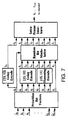
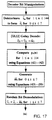
- a block diagram of the bit manipulations performed by the encoder is shown in Figure 7.
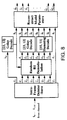
- the IMBE TM decoder reverses the bit manipulations performed by the encoder. First the decoder de-interleaves each frame of 144 bits to obtain the eight code vectors c ⁇ 0 , ..., c ⁇ 7 . The highest priority code vector is then error control decoded and used to generate a demodulation key. The demodulation key is then used to initialize a pseudo-random sequence which is converted into a set of binary modulation vectors.
- the IMBE TM speech decoder employs a number of different mechanisms to improve performance in the presence of bit errors. These mechanisms consist first of error control codes, which are able to remove a significant number of errors.
- the IMBE TM speech coder uses bit modulation combined with frame repeats and frame mutes to detect and discard highly corrupted frames.
- the IMBE TM speech decoder uses adaptive smoothing to reduce the perceived effect of any remaining errors.
- the first bit manipulation performed by the IMBE TM encoder is a prioritization of the quantizer values b ⁇ 0 , b ⁇ 1 , ..., b ⁇ +2 into a set of 8 bit vectors denoted by u ⁇ 0 , u ⁇ 1 , ..., u ⁇ 7 .
- the bits vectors u ⁇ 0 through u ⁇ 3 are 12 bits long, while the bit vectors u ⁇ 4 through u ⁇ 6 are 11 bits long, and the bit vector u ⁇ 7 is seven bits long.
- bit N where N is the vector length, is the most significant bit (MSB), and bit 1 is the least significant bit (LSB).
- the prioritization of the quantizer values into the set of bits vectors begins with u ⁇ 0 .
- the six most significant bits of u ⁇ 0 i.e. bits 12 through 7 are set equal to the six most significant bits of b ⁇ 0 (i.e. bits 8 through 3).
- the next three most significant bits of u ⁇ 0 i.e. bits 6 through 4) are set equal to the three most significant bits of b ⁇ 2 (i.e. bits 6 through 4).
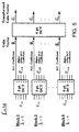
- the remaining three bits of u ⁇ 0 are generated from the spectral amplitude quantizer values b ⁇ 3 through b ⁇ +1 . Specifically these qauntizer values are arranged as shown in Figure 9.
- the remaining three bits of u ⁇ 0 are then selected by beginning in the upper left hand corner of this figure (i.e. bit 10 of b ⁇ 3 ) and scanning left to right. When the end of any row is reached the scanning proceeds from left to right on the next lower row. Bit 3 of u ⁇ 0 is set equal to the bit corresponding to the first shaded block which is encountered using the prescribed scanning order. Similarly, bit 2 of u ⁇ 0 is set equal to the bit corresponding to the second shaded block which is encountered and bit 1 of u ⁇ 0 is set equal to the bit corresponding to the third shaded block which is encountered.
- bit vectors u ⁇ 4 through u ⁇ 7 begins with of the V/UV decision bits. This is accomplished by inserting into the bit vectors (beginning with bit 11 of u ⁇ 4 , proceeding through bit 1 of u ⁇ 4 followed by bit 11 of u ⁇ 5 , and continuing in this manner until finally reaching bit 5 of u ⁇ 7 ) all of the bits of b ⁇ 1 (starting with the MSB), followed by bit 3 and then bit 2 of b ⁇ 2 , and then continuing with the scanning of b ⁇ 3 through b ⁇ +1 as described above.
- the final four bits of u ⁇ 7 (beginning with bit 4 and ending with bit 1) are set equal to bit 1 of b ⁇ 2 , bit 2 of b ⁇ 0 , bit 1 of b ⁇ 0 , and then bit 1 of b ⁇ +2 , respectively.
- bit vectors described above prioritizes the bits according to their sensitivity to bit errors.
- a bit error introduced into u ⁇ 0 generally causes the largest degradation in speech quality, while a bit error introduced into u ⁇ 7 generally causes little degradation in speech quality. Consequently the 56 bits per frame available for error control are used to protect the first four bit vectors with [23,12] Golay codes, while the next three bit vectors are protected with [15,11] Hamming codes. The last bit vector is left unprotected. This approach is efficient, since it only uses the more redundant (and hence more robust) Golay codes where they are most needed, while using less redundant (and hence less robust) codes in other areas.
- the bit prioritization described above can be viewed as assigning a weight to each allocated bit location in the set of quantizer values. Within any one quantizer value the weight is greater for a more significant bit location than for a less significant bit location. In addition the relative weight of a bit location of the same significance in different quantizer values is dependent upon each quantizer values sensitivity to bit errors (i.e. the perceived degradation that results after speech is synthesized with bit errors in a particular quantizer value). Once weight have been assigned to each bit location, then the contruction of the bit vectors is performed by ordering each bit according to the weight of its bit location and then partitioning the ordered bit sequence into bit vectors of the appropriate length.
- the eight bit vectors are each converted into a corresponding code vector.
- P G and P H are the parity matrices for the [23,12] Golay code and the [15,11] Hamming code, respectively. These are shown below where absent entries are assumed to equal zero. Note that all operations are modulo 2 as defined in the references cited herein, and the vectors v ⁇ i and u ⁇ i are assumed to be row vectors, where the "left" most bit is the MSB. This convention is used throughout this section.
- the Golay parity matrix P G shown above is a systematic representation of the standard [23,12] Golay code. Standard methods of decoding this code and the Hamming code are discussed in the literature. These methods are used by the IMBE TM decoder to correct the maximum number of errors for each code.
- the IMBE TM speech coder uses bit modulation to provide a mechanism for detecting errors in v ⁇ 0 beyond the three errors that the [23,12] Golay code can correct.
- the first step in this procedure is to generate a set of binary modulation vectors which are added (modulo 2) to the code vectors v ⁇ 0 through v ⁇ 7 .
- the modulation vectors are generated from a pseudo-random sequence which is initialized to the value of a modulation key which is generated from the bit vector u ⁇ 0 .
- p r (0) 16 u 0 where the bit vector u ⁇ 0 is interpreted as an unsigned 12 bit number in the range [0, 4095].
- Equation (42) is used to recursively compute the pseudo-random sequence p r ( n ) over the range 1 ⁇ n ⁇ 114.
- Each element of this sequence can be interpreted as a 16 bit random number which is uniformly distributed over the interval [0, 65535].
- a set of binary modulation vectors denoted by m ⁇ 0 through m ⁇ 7 , are generated from this sequence as shown below.
- the modulated code vectors v ⁇ 0 for 0 ⁇ i ⁇ 7, are computed by adding (modulo 2) the code vectors to the modulation vectors.
- c i v i + m i for 0 ⁇ i ⁇ 7
- bit modulation performed by the IMBE TM encoder can be inverted by the decoder if c ⁇ 0 does not contain any uncorrectable bit errors.
- the decoder can then use u ⁇ 0 to reconstruct the pseudo-random sequence and the modulation vectors m ⁇ 1 through m ⁇ 7 . Subtracting these vectors from c ⁇ 1 though c ⁇ 7 will then yield the code vectors v ⁇ 1 though v ⁇ 7 . At this point the remaining error control decoding can be performed.
- the IMBE TM decoder exploits the fact that, statistically, a 50 percent BER causes the Golay and Hamming codes employed on v ⁇ 1 through v ⁇ 6 to correct a number of errors which is near the maximum capability of the code. By counting the total number of errors which are corrected in all of these code vectors, the decoder is able to reliably detect frames in which c ⁇ 0 is likely to contain uncorrectable bit errors. The decoder performs frame repeats during these frames in order to reduce the perceived degradation in the presence of bit errors. Experimental results have shown that frame repeats are preferable to using an incorrectly decoded c ⁇ 0 , since this code vector controls the bit allocation for the parameter quantizers.
- the use of random bit modulation by the encoder allows the decoder to reliably detect whether there are any uncorrectable bit errors in c ⁇ 0 without requiring further redundancy to be placed into the data stream. This allow efficient use of the communication channel while eliminating large degradations from being introduced into the synthesized speech.
- Intra-frame bit interleaving is used to spread short bursts of errors among several code words. This decreases the probability that a short burst of errors will result in an uncorrectable error pattern.
- the minimum separation between any two bits of the same error correction code is 6 bits.
- the exact order of the 144 bits in each frame is tabulated in Appendix H of the APCO/NASTD/Fed Project 25 Vocoder Description dated 1 December 1992.
- bit N (where N is the vector length) is the MSB and bit 1 is the LSB.
- the speech coder bits should be inserted into the Project 25 frame format beginning with the bit t ⁇ 1 and ending with bit t ⁇ 144 .
- the IMBE TM speech decoder estimates the number of errors in each received data frame by computing the number of errors corrected by each of the [23,12] and [15,11] Hamming codes.
- the number of errors for each code vector is denoted ⁇ i for 0 ⁇ i ⁇ 6, where ⁇ i refers to the number of bit errors which were detected during the error control decoding of u ⁇ i .
- ⁇ i refers to the number of bit errors which were detected during the error control decoding of u ⁇ i .
- ⁇ R (0) is the estimate of the error rate for the current frame
- ⁇ R (-1) is the estimate of the error rate for the previous frame.
- the IMBE TM decoder examines each received data frame in order to detect and discard frames which are highly corrupted. A number of different fault conditions are checked and if any of these conditions indicate the current frame is invalid, then a frame repeat is performed.
- the IMBE TM speech encoder uses values of b ⁇ 0 in the range 0 ⁇ b ⁇ 0 ⁇ 207 to represent valid pitch estimates. In addition values of b ⁇ 0 in the range 216 ⁇ b ⁇ 0 ⁇ 219 are used by encoder to represent silence frames. The remaining values of b ⁇ 0 are reserved for future expansion (such as DTMF signals, call progress signals, enhanced speech coders, inband data, etc...) and are currently considered invalid.
- a frame repeat is performed by the decoder if it receives an invalid value of b ⁇ 0 , or if both of the following two equations are true. ⁇ 0 ⁇ 2 ⁇ T ⁇ 11 These two equations are used to detect the incorrect demodulation which results if there are uncorrectable bit errors in c ⁇ 0 .
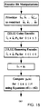
- the decoder performs a frame repeat by taking the following steps:
- the IMBETM decoder uses muting to squelch the output in severe bit error environments. This is indicated after four successive frames have been repeated or if ⁇ R > .085.
- the decoder mutes the speech output if a silence frame is received which is indicated by 216 ⁇ b ⁇ 0 ⁇ 219.
- the recommended muting method is to bypass the synthesis procedure and to set the synthetic speech signal, s ⁇ ( n ) to random noise which is uniformly distributed over the interval [-5, 5] samples.
- the logic used to detect an incorrect demodulation of the current frame is controlled by the parameters ⁇ i for 0 ⁇ i ⁇ 6, which represent the number of errors detected during the error control decoding of v ⁇ i .
- This detection logic can be generalized to the computation of an error measure based upon the result of comparing v ⁇ i with u ⁇ i (i.e. the demodulated code vectors before and after error control decoding). If the value of this error measure exceeds a threshold then the current frame is declared invalid. This relies on the fact that incorrect demodulation causes large discrepancies between these vectors, resulting in a high value of the error measure.
- Some appropriate action such as a frame repeat or a frame mute, is then performed for invalid frames.
- the advantage of this generalized viewpoint is that it easily accomodates alternative error measures which may offer improved performance under certain channel conditions. For example soft-decision (i.e. multi-bit) data from a modem or similar device can be combined with the disclosed demodulation method in a straightforward manner to offer improved performance.
- the IMBE TM speech decoder attempts to improve the perceived quality of the synthesized speech by enhancing the spectral amplitudes.
- the unenhanced spectral amplitudes are required by future frames in the computation of Equation (34). However, the enhanced spectral amplitudes are used in speech synthesis.
- the spectral amplitude enhancement is accomplished by generating a set of spectral weights from the model parameters of the current frame.
- W l M l ⁇ .96 ⁇ ( R 2 M 0 + R 2 M 1 -2 R M 0 R M 1 cos( ⁇ 0 l )) ⁇ 0 R M 0 ( R 2 M 0 + R 2 M 1 ) 1 4 for 1 ⁇ l ⁇ L
- a final step is to scale the enhanced spectral amplitudes in
- Equation (68) The correct scale factor, denoted by ⁇ , is given below.
- This scale factor is applied to each to each of the enhanced spectral amplitudes as shown in Equation (68).
- M l ⁇ ⁇ M l for 1 ⁇ l ⁇ L
- this equation refers to both the scaled and unscaled spectral amplitudes as M l . This convention has been adopted since the unscaled amplitudes are discarded and only the scaled amplitudes are subsequently used by the decoder during parameter smoothing and speech synthesis.
- Equation (64) The value of R M 0 expressed in Equation (64) is a measure of the energy in the current frame. This value is used to update a local energy parameter in accordance with the following rule. This equation generates the local energy parameter for the current frame, S E (0), from R M 0 and the value of the local energy parameter from the previous frame S E (-1). The parameter S E (0) is used to adaptively smooth the V/UV decisions as described below.
- the IMBE TM decoder performs adaptive smoothing to reduce the perceived distortion caused by any uncorrectable bit errors in b ⁇ 0 , b ⁇ 1 , ..., b ⁇ L +2 .
- the adaptive smoothing methods are controlled by two error rate parameters, ⁇ T and ⁇ R , which are estimated for the current frame as discussed above.
- ⁇ T and ⁇ R are small, it is assumed that the error control decoding removed all of the bit errors, and the decoded model parameters are not perturbed.
- ⁇ T and ⁇ R are small, it is assumed that their is a high probability that some uncorrected bit errors have been introduced into the decoded model parameters, and a large amount of smoothing is peformed.
- the first parameters to be smoothed by the decoder are the V/UV decisions.
- V M is calculated using equation (70), where the energy parameter S E (0) is defined in Equation (69).
- S E (0) is defined in Equation (69).
- each enhanced spectral amplitude M l for 1 ⁇ l ⁇ L ⁇ is compared against V M , and if M l > V M then the V/UV decision for that spectral amplitude is declared voiced, regardless of the decoded V/UV decision. Otherwise the decoded V/UV decision for that spectral amplitude is left unchanged. This process can be expressed mathematically as shown below.
- the decoder adaptively smooths the spectral amplitudes M l for 1 ⁇ l ⁇ L ⁇ .
- the spectral amplitude smoothing method computes the following amplitude measure for the current segment.
- an amplitude threshold is updated according to the following equation, where ⁇ M (0) and ⁇ M (-1) represent the value of the amplitude threshold for the current and previous frames respectively.
- the two parameters A M and ⁇ M (0) are then used to compute a scale factor ⁇ M given below. This scale factor is multiplied by each of the spectral amplitudes M l for 1 ⁇ l ⁇ L ⁇ . Note that this step must be completed after spectral amplitude enhancement has been performed and after V M has been computed according to Equation 70.
- the correct sequence is shown in Figure 12.
Landscapes
- Engineering & Computer Science (AREA)
- Physics & Mathematics (AREA)
- Signal Processing (AREA)
- Probability & Statistics with Applications (AREA)
- Theoretical Computer Science (AREA)
- Computer Networks & Wireless Communication (AREA)
- Health & Medical Sciences (AREA)
- Computational Linguistics (AREA)
- Audiology, Speech & Language Pathology (AREA)
- Human Computer Interaction (AREA)
- Acoustics & Sound (AREA)
- Multimedia (AREA)
- Spectroscopy & Molecular Physics (AREA)
- Algebra (AREA)
- General Physics & Mathematics (AREA)
- Mathematical Physics (AREA)
- Pure & Applied Mathematics (AREA)
- Compression, Expansion, Code Conversion, And Decoders (AREA)
Claims (18)
- Verfahren zum Codieren von Digitaldaten, wobei das Verfahren die Schritte aufweist:Teilen der Digitaldaten in einen oder mehrere Rahmen;ferner, Teilen jedes der Rahmen in eine Mehrzahl von Bitvektoren;Codieren eines oder mehrerer der Bitvektoren mit Fehlerüberwachungscodes;
und dadurch gekennzeichnet, dass es ferner die Schritte aufweist:Erzeugen eines Modulationsschlüssels aus einem oder mehreren der Bitvektoren; undVerwenden des Modulationsschlüssels zum Modulieren eines oder mehrerer der codierten Bitvektoren. - Verfahren nach Anspruch 1, wobei eine erste Gruppe der Bitvektoren jeweils durch einen ersten Typ von Fehlerüberwachungscode codiert wird und eine zweite Gruppe der Bitvektoren jeweils durch einen zweiten Typ von Fehlerüberwachungscode codiert wird.
- Verfahren nach Anspruch 1 oder 2, wobei der Modulationsschlüssel aus einem prioritätshohen Bitvektor erzeugt wird.
- Verfahren nach Anspruch 1 oder 2, wobei die Digitaldaten-Rahmen durch Codieren eines Sprachsignals mit einem Sprachcodierer erzeugt werden.
- Verfahren nach Anspruch 4, wobei die Digitaldaten-Rahmen in eine Mehrzahl von Rahmenformaten gruppiert werden können und wobei der Modulationsschlüssel aus einem der Bitvektoren erzeugt wird, wobei der eine Bitvektor das im gegenwärtigen Rahmen verwendete Rahmenformat bestimmt.
- Verfahren zum Decodieren von Digitaldaten, die unter Verwendung des Verfahrens von Anspruch 1 codiert worden sind, wobei das Verfahren die Schritte aufweist:Teilen der Digitaldaten in einen oder mehrere Rahmen;ferner, Teilen jedes der Rahmen in eine Mehrzahl von Codevektoren;Erzeugen eines Demodulationsschlüssels aus einem oder mehreren der Codevektoren;Verwenden des Demodulationsschlüssels zum Demodulieren eines oder mehrerer der Codevektoren; undFehlerüberwachungs-Decodieren eines oder mehrerer der demodulierten Codevektoren.
- Verfahren nach Anspruch 6, das ferner die Schritte aufweist:Berechnen eines Fehlermaßes, das zumindest teilweise durch Vergleichen der vor der Fehlerüberwachungs-Decodierung demodulierten Codevektoren mit den nach der Fehlerüberwachungs-Decodierung demodulierten Codevektoren gebildet wird;Vergleichen des Weit des Fehlermaßes gegenüber einem Schwellenwert; undUngültigerklären des Rahmens, wenn das Fehlermaß den Schwellenwert überschreitet.
- Verfahren nach Anspruch 7, wobei die Demodulation unter Verwendung eines Verfahrens durchgeführt wird, das die Schritte aufweist:Initialisieren einer pseudozufälligen Sequenz unter Verwendung des Demodulationsschlüssels;Verwenden der pseudozufälligen Sequenz zum Erzeugen eines oder mehrerer binärer Demodulationsvektoren; undDurchführen einer Modulo-2-Addition der binären Demodulationsvektoren zu einer Mehrzahl der Codevektoren.
- Verfahren nach Anspruch 8, wobei der Demodulationsschlüssel von einem der Codevektoren erzeugt wird, nachdem der eine Codevektor fehlerüberwachend decodiert worden ist.
- Verfahren nach Anspruch 6, 7, 8 oder 9, wobei eine erste Gruppe der demodulierten Codevektoren jeweils unter Verwendung eines ersten Typs von Fehlerüberwachungscodes decodiert wird und eine zweite Gruppe der demodulierten Codevektoren jeweils unter Verwendung eines zweiten Typs von Fehlerüberwachungscodes decodiert wird.
- Verfahren nach Anspruch 10, wobei der erste Typ von Fehlerüberwachungscode ein Golay-Code ist und der zweite Typ von Fehlerüberwachungscode ein Hamming-Code ist.
- Verfahren nach Anspruch 6, 7, 8 oder 9, wobei der Demodulationsschlüssel aus einem prioritätshohen Codevektor erzeugt wird.
- Verfahren nach Anspruch 7, 8 oder 9, wobei das Fehlermaß zumindest teilweise durch Zählen der Anzahl von Fehlern berechnet wird, die durch die Fehlerüberwachungs-Decodierung erfasst oder korrigiert werden.
- Verfahren nach Anspruch 12, wobei die Digitaldaten-Rahmen ein Sprachsignal repräsentieren, das mit einem Sprachcodierer codiert worden ist.
- Verfahren nach Anspruch 14, wobei die Digitaldaten-Rahmen in eine Mehrzahl von Rahmenformaten gruppiert werden können und wobei der Demodulationsschlüssel aus einem der Codevektoren erzeugt wird, wobei der eine Codevektor das in jedem Rahmen verwendete Rahmenformat bestimmt.
- Verfahren nach Anspruch 14, wobei der Demodulationsschlüssel aus einem der Codevektoren erzeugt wird, wobei der eine Codevektor zumindest teilweise den Pegel des Sprachsignals repräsentiert.
- Verfahren nach Anspruch 14, wobei die ungültigen Rahmen verworfen werden und durch den zuletzt decodierten Rahmen ersetzt werden, der nicht als ungültig erklärt worden ist.
- Verfahren nach Anspruch 14, wobei der Sprachcodierer einer der folgenden Sprachcodierer ist: ein Mehrband-Erregungs(MBE)-Sprachcodierer, ein Verbesserter-Mehrband-Erregungs(IMBE™)-Sprachcodierer oder ein Sinuswandler-Sprachcodierer (STC).
Priority Applications (1)
| Application Number | Priority Date | Filing Date | Title |
|---|---|---|---|
| EP99114399A EP0955586B1 (de) | 1992-11-30 | 1993-11-29 | Kodierung mit Modulation, Fehlerkontrolle, Gewichtung und Bitzuordnung |
Applications Claiming Priority (3)
| Application Number | Priority Date | Filing Date | Title |
|---|---|---|---|
| US07/982,937 US5517511A (en) | 1992-11-30 | 1992-11-30 | Digital transmission of acoustic signals over a noisy communication channel |
| US982937 | 1992-11-30 | ||
| PCT/US1993/011609 WO1994012932A1 (en) | 1992-11-30 | 1993-11-29 | Coding with modulation, error control, weighting, and bit allocation |
Related Child Applications (1)
| Application Number | Title | Priority Date | Filing Date |
|---|---|---|---|
| EP99114399A Division EP0955586B1 (de) | 1992-11-30 | 1993-11-29 | Kodierung mit Modulation, Fehlerkontrolle, Gewichtung und Bitzuordnung |
Publications (3)
| Publication Number | Publication Date |
|---|---|
| EP0671032A1 EP0671032A1 (de) | 1995-09-13 |
| EP0671032A4 EP0671032A4 (de) | 1996-08-14 |
| EP0671032B1 true EP0671032B1 (de) | 2000-03-08 |
Family
ID=25529664
Family Applications (2)
| Application Number | Title | Priority Date | Filing Date |
|---|---|---|---|
| EP99114399A Expired - Lifetime EP0955586B1 (de) | 1992-11-30 | 1993-11-29 | Kodierung mit Modulation, Fehlerkontrolle, Gewichtung und Bitzuordnung |
| EP94902473A Expired - Lifetime EP0671032B1 (de) | 1992-11-30 | 1993-11-29 | Kodierung mit modulation, fehlerkontrolle, gewichtung und bitzuordnung |
Family Applications Before (1)
| Application Number | Title | Priority Date | Filing Date |
|---|---|---|---|
| EP99114399A Expired - Lifetime EP0955586B1 (de) | 1992-11-30 | 1993-11-29 | Kodierung mit Modulation, Fehlerkontrolle, Gewichtung und Bitzuordnung |
Country Status (5)
| Country | Link |
|---|---|
| US (2) | US5517511A (de) |
| EP (2) | EP0955586B1 (de) |
| AU (1) | AU5683394A (de) |
| DE (2) | DE69331886T2 (de) |
| WO (1) | WO1994012932A1 (de) |
Families Citing this family (76)
| Publication number | Priority date | Publication date | Assignee | Title |
|---|---|---|---|---|
| US5517511A (en) * | 1992-11-30 | 1996-05-14 | Digital Voice Systems, Inc. | Digital transmission of acoustic signals over a noisy communication channel |
| US6449377B1 (en) * | 1995-05-08 | 2002-09-10 | Digimarc Corporation | Methods and systems for watermark processing of line art images |
| US6944298B1 (en) * | 1993-11-18 | 2005-09-13 | Digimare Corporation | Steganographic encoding and decoding of auxiliary codes in media signals |
| US6614914B1 (en) | 1995-05-08 | 2003-09-02 | Digimarc Corporation | Watermark embedder and reader |
| US5748763A (en) * | 1993-11-18 | 1998-05-05 | Digimarc Corporation | Image steganography system featuring perceptually adaptive and globally scalable signal embedding |
| US6611607B1 (en) * | 1993-11-18 | 2003-08-26 | Digimarc Corporation | Integrating digital watermarks in multimedia content |
| FI98163C (fi) * | 1994-02-08 | 1997-04-25 | Nokia Mobile Phones Ltd | Koodausjärjestelmä parametriseen puheenkoodaukseen |
| US6560349B1 (en) * | 1994-10-21 | 2003-05-06 | Digimarc Corporation | Audio monitoring using steganographic information |
| AU696092B2 (en) * | 1995-01-12 | 1998-09-03 | Digital Voice Systems, Inc. | Estimation of excitation parameters |
| WO1996025802A2 (en) * | 1995-02-07 | 1996-08-22 | Ntp Incorporated | System, transmitting and receiving circuitry for serially transmitting and serially receiving encoded information and method of operation |
| US5754974A (en) * | 1995-02-22 | 1998-05-19 | Digital Voice Systems, Inc | Spectral magnitude representation for multi-band excitation speech coders |
| US5701390A (en) * | 1995-02-22 | 1997-12-23 | Digital Voice Systems, Inc. | Synthesis of MBE-based coded speech using regenerated phase information |
| US6760463B2 (en) * | 1995-05-08 | 2004-07-06 | Digimarc Corporation | Watermarking methods and media |
| EP0756386B1 (de) * | 1995-07-27 | 2003-09-17 | Victor Company Of Japan, Limited | Verfahren und Gerät zum Kodieren digitaler akustischer Signale |
| US5774837A (en) * | 1995-09-13 | 1998-06-30 | Voxware, Inc. | Speech coding system and method using voicing probability determination |
| GB9523406D0 (en) * | 1995-11-16 | 1996-01-17 | Aromascan Plc | Sensor transduction |
| US6170073B1 (en) * | 1996-03-29 | 2001-01-02 | Nokia Mobile Phones (Uk) Limited | Method and apparatus for error detection in digital communications |
| US7788092B2 (en) * | 1996-09-25 | 2010-08-31 | Qualcomm Incorporated | Method and apparatus for detecting bad data packets received by a mobile telephone using decoded speech parameters |
| CA2265640A1 (en) * | 1996-09-25 | 1998-04-02 | Qualcomm Incorporated | Method and apparatus for detecting bad data packets received by a mobile telephone using decoded speech parameters |
| US5968199A (en) * | 1996-12-18 | 1999-10-19 | Ericsson Inc. | High performance error control decoder |
| US6131084A (en) * | 1997-03-14 | 2000-10-10 | Digital Voice Systems, Inc. | Dual subframe quantization of spectral magnitudes |
| US6161089A (en) * | 1997-03-14 | 2000-12-12 | Digital Voice Systems, Inc. | Multi-subframe quantization of spectral parameters |
| AU7655298A (en) * | 1997-07-02 | 1999-01-25 | Alcatel Alsthom Compagnie Generale D'electricite | Device for transmitting a coded adpcm voice signal |
| US6000054A (en) * | 1997-11-03 | 1999-12-07 | Motorola, Inc. | Method and apparatus for encoding and decoding binary information using restricted coded modulation and parallel concatenated convolution codes |
| US6199037B1 (en) | 1997-12-04 | 2001-03-06 | Digital Voice Systems, Inc. | Joint quantization of speech subframe voicing metrics and fundamental frequencies |
| KR100341044B1 (ko) * | 1997-12-08 | 2002-07-13 | 다니구찌 이찌로오, 기타오카 다카시 | 음성 신호 가공 방법 및 음성 신호 가공 장치 |
| KR19990065424A (ko) * | 1998-01-13 | 1999-08-05 | 윤종용 | 저지연 다중밴드 여기 보코더를 위한 피치 결정방식 |
| US6405338B1 (en) * | 1998-02-11 | 2002-06-11 | Lucent Technologies Inc. | Unequal error protection for perceptual audio coders |
| US6356600B1 (en) * | 1998-04-21 | 2002-03-12 | The United States Of America As Represented By The Secretary Of The Navy | Non-parametric adaptive power law detector |
| US6871302B1 (en) * | 1998-05-27 | 2005-03-22 | Ntt Mobile Communications Network, Inc. | Method and device for interleaving and method and device for deinterleaving |
| US6263087B1 (en) * | 1998-06-26 | 2001-07-17 | Signafy, Inc. | Method of encoding bits in a signal |
| US6272176B1 (en) | 1998-07-16 | 2001-08-07 | Nielsen Media Research, Inc. | Broadcast encoding system and method |
| US7103065B1 (en) * | 1998-10-30 | 2006-09-05 | Broadcom Corporation | Data packet fragmentation in a cable modem system |
| US6357029B1 (en) * | 1999-01-27 | 2002-03-12 | Agere Systems Guardian Corp. | Joint multiple program error concealment for digital audio broadcasting and other applications |
| US6377915B1 (en) * | 1999-03-17 | 2002-04-23 | Yrp Advanced Mobile Communication Systems Research Laboratories Co., Ltd. | Speech decoding using mix ratio table |
| US6377916B1 (en) | 1999-11-29 | 2002-04-23 | Digital Voice Systems, Inc. | Multiband harmonic transform coder |
| US6397368B1 (en) * | 1999-12-06 | 2002-05-28 | Intellon Corporation | Forward error correction with channel adaptation |
| US6587826B1 (en) * | 1999-12-15 | 2003-07-01 | Agere Systems Inc. | Channel code configurations for digital audio broadcasting systems and other types of communication systems |
| US20010041981A1 (en) * | 2000-02-22 | 2001-11-15 | Erik Ekudden | Partial redundancy encoding of speech |
| US6892343B2 (en) | 2000-03-27 | 2005-05-10 | Board Of Regents Of The University Of Nebraska | System and method for joint source-channel encoding, with symbol decoding and error correction |
| US7080009B2 (en) * | 2000-05-01 | 2006-07-18 | Motorola, Inc. | Method and apparatus for reducing rate determination errors and their artifacts |
| US6606726B1 (en) | 2000-06-13 | 2003-08-12 | Telefonaktiebolaget L M Ericsson (Publ) | Optimization of acceptance of erroneous codewords and throughput |
| IL154651A0 (en) * | 2000-08-29 | 2003-09-17 | Ntru Cryptosystems Inc | Speed enhanced cryptographic method and apparatus |
| US20020188424A1 (en) * | 2001-04-20 | 2002-12-12 | Grinstein Georges G. | Method and system for data analysis |
| WO2002102007A1 (en) * | 2001-06-09 | 2002-12-19 | Samsung Electronics Co., Ltd | Method and apparatus for rearranging codeword sequence in a communication system |
| EP1425859A4 (de) * | 2001-08-09 | 2009-01-07 | Adaptive Networks Inc | Fehlerkorrekturprozess und -mechanismus |
| KR100703295B1 (ko) * | 2001-08-18 | 2007-04-03 | 삼성전자주식회사 | 이동통신시스템에서 안테나 어레이를 이용한 데이터 송/수신 장치 및 방법 |
| US6904540B2 (en) | 2001-10-29 | 2005-06-07 | Hewlett-Packard Development Company, L.P. | Targeted data protection |
| JP4245288B2 (ja) * | 2001-11-13 | 2009-03-25 | パナソニック株式会社 | 音声符号化装置および音声復号化装置 |
| US6973579B2 (en) | 2002-05-07 | 2005-12-06 | Interdigital Technology Corporation | Generation of user equipment identification specific scrambling code for the high speed shared control channel |
| US7764716B2 (en) * | 2002-06-21 | 2010-07-27 | Disney Enterprises, Inc. | System and method for wirelessly transmitting and receiving digital data using acoustical tones |
| DE10230809B4 (de) * | 2002-07-08 | 2008-09-11 | T-Mobile Deutschland Gmbh | Verfahren zur Übertragung von Audiosignalen nach dem Verfahren der priorisierenden Pixelübertragung |
| US7970606B2 (en) * | 2002-11-13 | 2011-06-28 | Digital Voice Systems, Inc. | Interoperable vocoder |
| US7240260B2 (en) * | 2002-12-11 | 2007-07-03 | Intel Corporation | Stimulus generation |
| US7634399B2 (en) * | 2003-01-30 | 2009-12-15 | Digital Voice Systems, Inc. | Voice transcoder |
| US8359197B2 (en) * | 2003-04-01 | 2013-01-22 | Digital Voice Systems, Inc. | Half-rate vocoder |
| US20050091041A1 (en) * | 2003-10-23 | 2005-04-28 | Nokia Corporation | Method and system for speech coding |
| US20050091044A1 (en) * | 2003-10-23 | 2005-04-28 | Nokia Corporation | Method and system for pitch contour quantization in audio coding |
| US7684505B2 (en) * | 2004-04-26 | 2010-03-23 | Qualcomm Incorporated | Method and apparatus for encoding interleaving and mapping data to facilitate GBPS data rates in wireless systems |
| US7599363B2 (en) * | 2004-08-13 | 2009-10-06 | Samsung Electronics Co. Ltd | Method for reporting reception result of packets in mobile communication system |
| US7885809B2 (en) * | 2005-04-20 | 2011-02-08 | Ntt Docomo, Inc. | Quantization of speech and audio coding parameters using partial information on atypical subsequences |
| US20070180349A1 (en) * | 2006-01-31 | 2007-08-02 | Jacobsen Eric A | Techniques for uequal error protection for layered protection applications |
| CA2657171A1 (en) * | 2006-07-28 | 2008-01-31 | Qualcomm Incorporated | Data encoding method and apparatus for flash-type signaling |
| US7958433B1 (en) * | 2006-11-30 | 2011-06-07 | Marvell International Ltd. | Methods and systems for storing data in memory using zoning |
| US8036886B2 (en) | 2006-12-22 | 2011-10-11 | Digital Voice Systems, Inc. | Estimation of pulsed speech model parameters |
| JP5256756B2 (ja) * | 2008-02-05 | 2013-08-07 | パナソニック株式会社 | Adpcm音声伝送システムの音声処理装置およびその音声処理方法 |
| US8195452B2 (en) * | 2008-06-12 | 2012-06-05 | Nokia Corporation | High-quality encoding at low-bit rates |
| KR101236054B1 (ko) * | 2008-07-17 | 2013-02-21 | 노키아 코포레이션 | 벡터 양자화기를 위한 고속 최근접 이웃 탐색용 방법, 장치 및 컴퓨터 판독 가능한 기록 매체 |
| CN103368682B (zh) * | 2012-03-29 | 2016-12-07 | 华为技术有限公司 | 信号编码和解码的方法和设备 |
| WO2014154271A1 (en) * | 2013-03-27 | 2014-10-02 | Irdeto B.V. | Data processing |
| IT201900017273A1 (it) * | 2019-09-26 | 2021-03-26 | Pasquale Ciccimarra | Metodo per rendere sicuro un dispositivo elettronico |
| US11270714B2 (en) | 2020-01-08 | 2022-03-08 | Digital Voice Systems, Inc. | Speech coding using time-varying interpolation |
| US12254895B2 (en) | 2021-07-02 | 2025-03-18 | Digital Voice Systems, Inc. | Detecting and compensating for the presence of a speaker mask in a speech signal |
| US11990144B2 (en) | 2021-07-28 | 2024-05-21 | Digital Voice Systems, Inc. | Reducing perceived effects of non-voice data in digital speech |
| US12451151B2 (en) | 2022-04-08 | 2025-10-21 | Digital Voice Systems, Inc. | Tone frame detector for digital speech |
| US12462814B2 (en) | 2023-10-06 | 2025-11-04 | Digital Voice Systems, Inc. | Bit error correction in digital speech |
Citations (1)
| Publication number | Priority date | Publication date | Assignee | Title |
|---|---|---|---|---|
| US4799059A (en) * | 1986-03-14 | 1989-01-17 | Enscan, Inc. | Automatic/remote RF instrument monitoring system |
Family Cites Families (48)
| Publication number | Priority date | Publication date | Assignee | Title |
|---|---|---|---|---|
| US2949505A (en) * | 1957-08-14 | 1960-08-16 | Bell Telephone Labor Inc | Reduced bandwith transmission system |
| US3674939A (en) * | 1969-11-26 | 1972-07-04 | Fred A Brooks | Baseband pulse code modulation system |
| US3982070A (en) * | 1974-06-05 | 1976-09-21 | Bell Telephone Laboratories, Incorporated | Phase vocoder speech synthesis system |
| US3975587A (en) * | 1974-09-13 | 1976-08-17 | International Telephone And Telegraph Corporation | Digital vocoder |
| US4047151A (en) * | 1974-12-24 | 1977-09-06 | Rydbeck Nils R C | Adaptive error correcting transmission system |
| GB1563801A (en) * | 1975-11-03 | 1980-04-02 | Post Office | Error correction of digital signals |
| FR2412987A1 (fr) * | 1977-12-23 | 1979-07-20 | Ibm France | Procede de compression de donnees relatives au signal vocal et dispositif mettant en oeuvre ledit procede |
| US4232194A (en) * | 1979-03-16 | 1980-11-04 | Ocean Technology, Inc. | Voice encryption system |
| US4276647A (en) * | 1979-08-02 | 1981-06-30 | Xerox Corporation | High speed Hamming code circuit and method for the correction of error bursts |
| US4312198A (en) * | 1979-08-09 | 1982-01-26 | Sedley Bruce S | Magnetic key operated hotel door lock |
| JPS5625853A (en) * | 1979-08-09 | 1981-03-12 | Mitsubishi Electric Corp | Information transmission system |
| JPS57123747A (en) * | 1981-01-24 | 1982-08-02 | Mitsubishi Electric Corp | Loop transmitting method |
| ATE15415T1 (de) * | 1981-09-24 | 1985-09-15 | Gretag Ag | Verfahren und vorrichtung zur redundanzvermindernden digitalen sprachverarbeitung. |
| AU570439B2 (en) * | 1983-03-28 | 1988-03-17 | Compression Labs, Inc. | A combined intraframe and interframe transform coding system |
| JPS60142430A (ja) * | 1983-12-28 | 1985-07-27 | Fujitsu Ltd | 誤り訂正・検出装置 |
| NL8400728A (nl) * | 1984-03-07 | 1985-10-01 | Philips Nv | Digitale spraakcoder met basisband residucodering. |
| US4648091A (en) * | 1984-07-02 | 1987-03-03 | General Electric Company | Apparatus and method for decoding error correction coded information |
| US4622680A (en) * | 1984-10-17 | 1986-11-11 | General Electric Company | Hybrid subband coder/decoder method and apparatus |
| US4885790A (en) * | 1985-03-18 | 1989-12-05 | Massachusetts Institute Of Technology | Processing of acoustic waveforms |
| FR2583240B1 (fr) * | 1985-06-05 | 1994-02-04 | France Telediffusion | Procede de transmission en blocs de mots d'information numerique |
| US4879748A (en) * | 1985-08-28 | 1989-11-07 | American Telephone And Telegraph Company | Parallel processing pitch detector |
| US4726029A (en) * | 1985-09-10 | 1988-02-16 | Hycom Incorporated | Error-correcting modem |
| US4720861A (en) * | 1985-12-24 | 1988-01-19 | Itt Defense Communications A Division Of Itt Corporation | Digital speech coding circuit |
| JPS6348030A (ja) * | 1986-08-15 | 1988-02-29 | Nec Corp | パケツト交換システム |
| US4797926A (en) * | 1986-09-11 | 1989-01-10 | American Telephone And Telegraph Company, At&T Bell Laboratories | Digital speech vocoder |
| US4882733A (en) * | 1987-03-13 | 1989-11-21 | Ford Aerospace Corporation | Method and apparatus for combining encoding and modulation |
| US5095392A (en) * | 1988-01-27 | 1992-03-10 | Matsushita Electric Industrial Co., Ltd. | Digital signal magnetic recording/reproducing apparatus using multi-level QAM modulation and maximum likelihood decoding |
| US5023910A (en) * | 1988-04-08 | 1991-06-11 | At&T Bell Laboratories | Vector quantization in a harmonic speech coding arrangement |
| NL8801155A (nl) * | 1988-05-03 | 1989-12-01 | Philips Nv | Televisie-overdrachtsysteem met hybride kodeerschakeling. |
| BR9007062A (pt) * | 1989-01-27 | 1991-10-08 | Dolby Lab Licensing Corp | Codificador,descodificador e codificador/descodificador de transformada de retardo de tempo baixo para audio de alta qualidade |
| US5007094A (en) * | 1989-04-07 | 1991-04-09 | Gte Products Corporation | Multipulse excited pole-zero filtering approach for noise reduction |
| US5042069A (en) * | 1989-04-18 | 1991-08-20 | Pacific Communications Sciences, Inc. | Methods and apparatus for reconstructing non-quantized adaptively transformed voice signals |
| JPH0782359B2 (ja) * | 1989-04-21 | 1995-09-06 | 三菱電機株式会社 | 音声符号化装置、音声復号化装置及び音声符号化・復号化装置 |
| WO1990013112A1 (fr) * | 1989-04-25 | 1990-11-01 | Kabushiki Kaisha Toshiba | Codeur vocal |
| US5036515A (en) * | 1989-05-30 | 1991-07-30 | Motorola, Inc. | Bit error rate detection |
| JPH0398318A (ja) * | 1989-09-11 | 1991-04-23 | Fujitsu Ltd | 音声符号化方式 |
| US5081681B1 (en) * | 1989-11-30 | 1995-08-15 | Digital Voice Systems Inc | Method and apparatus for phase synthesis for speech processing |
| US5097507A (en) * | 1989-12-22 | 1992-03-17 | General Electric Company | Fading bit error protection for digital cellular multi-pulse speech coder |
| GB9010637D0 (en) * | 1990-05-11 | 1990-07-04 | Secr Defence | A high frequency multichannel diversity differential phase shift(dpsk)communications system |
| JP2841765B2 (ja) * | 1990-07-13 | 1998-12-24 | 日本電気株式会社 | 適応ビット割当て方法及び装置 |
| US5226108A (en) * | 1990-09-20 | 1993-07-06 | Digital Voice Systems, Inc. | Processing a speech signal with estimated pitch |
| US5216747A (en) * | 1990-09-20 | 1993-06-01 | Digital Voice Systems, Inc. | Voiced/unvoiced estimation of an acoustic signal |
| US5247579A (en) * | 1990-12-05 | 1993-09-21 | Digital Voice Systems, Inc. | Methods for speech transmission |
| US5226084A (en) * | 1990-12-05 | 1993-07-06 | Digital Voice Systems, Inc. | Methods for speech quantization and error correction |
| KR0125581B1 (ko) * | 1991-07-24 | 1998-07-01 | 구자홍 | 디지탈 영상신호의 에러수정 시스템 |
| US5285498A (en) * | 1992-03-02 | 1994-02-08 | At&T Bell Laboratories | Method and apparatus for coding audio signals based on perceptual model |
| US5295159A (en) * | 1992-04-17 | 1994-03-15 | Bell Communications Research, Inc. | Coordinated coding for digital transmission |
| US5517511A (en) * | 1992-11-30 | 1996-05-14 | Digital Voice Systems, Inc. | Digital transmission of acoustic signals over a noisy communication channel |
-
1992
- 1992-11-30 US US07/982,937 patent/US5517511A/en not_active Expired - Lifetime
-
1993
- 1993-11-29 EP EP99114399A patent/EP0955586B1/de not_active Expired - Lifetime
- 1993-11-29 EP EP94902473A patent/EP0671032B1/de not_active Expired - Lifetime
- 1993-11-29 DE DE69331886T patent/DE69331886T2/de not_active Expired - Lifetime
- 1993-11-29 AU AU56833/94A patent/AU5683394A/en not_active Abandoned
- 1993-11-29 DE DE69328034T patent/DE69328034T2/de not_active Expired - Lifetime
- 1993-11-29 WO PCT/US1993/011609 patent/WO1994012932A1/en not_active Ceased
-
1996
- 1996-03-04 US US08/610,184 patent/US5870405A/en not_active Expired - Lifetime
Patent Citations (1)
| Publication number | Priority date | Publication date | Assignee | Title |
|---|---|---|---|---|
| US4799059A (en) * | 1986-03-14 | 1989-01-17 | Enscan, Inc. | Automatic/remote RF instrument monitoring system |
Also Published As
| Publication number | Publication date |
|---|---|
| EP0955586B1 (de) | 2002-05-02 |
| EP0671032A4 (de) | 1996-08-14 |
| DE69328034T2 (de) | 2000-12-21 |
| DE69328034D1 (de) | 2000-04-13 |
| EP0671032A1 (de) | 1995-09-13 |
| WO1994012932A1 (en) | 1994-06-09 |
| DE69331886D1 (de) | 2002-06-06 |
| EP0955586A1 (de) | 1999-11-10 |
| AU5683394A (en) | 1994-06-22 |
| US5870405A (en) | 1999-02-09 |
| US5517511A (en) | 1996-05-14 |
| DE69331886T2 (de) | 2002-11-14 |
Similar Documents
| Publication | Publication Date | Title |
|---|---|---|
| EP0671032B1 (de) | Kodierung mit modulation, fehlerkontrolle, gewichtung und bitzuordnung | |
| US5247579A (en) | Methods for speech transmission | |
| EP0893791B1 (de) | Verfahren zur Kodierung von Sprachsignalen | |
| US6131084A (en) | Dual subframe quantization of spectral magnitudes | |
| EP1061503B1 (de) | Fehlererkennung und Fehlerverdeckung für kodierte Sprachdaten | |
| US4831624A (en) | Error detection method for sub-band coding | |
| US8359197B2 (en) | Half-rate vocoder | |
| US8315860B2 (en) | Interoperable vocoder | |
| US5754974A (en) | Spectral magnitude representation for multi-band excitation speech coders | |
| CN1153399C (zh) | 用于提高当前语音帧质量的方法和无线系统 | |
| US7957963B2 (en) | Voice transcoder | |
| US6199037B1 (en) | Joint quantization of speech subframe voicing metrics and fundamental frequencies | |
| CA2149039C (en) | Coding with modulation, error control, weighting, and bit allocation | |
| KR100220783B1 (ko) | 음성 양자화 및 에러 보정 방법 |
Legal Events
| Date | Code | Title | Description |
|---|---|---|---|
| PUAI | Public reference made under article 153(3) epc to a published international application that has entered the european phase |
Free format text: ORIGINAL CODE: 0009012 |
|
| AK | Designated contracting states |
Kind code of ref document: A1 Designated state(s): DE FR GB SE |
|
| 17P | Request for examination filed |
Effective date: 19950511 |
|
| A4 | Supplementary search report drawn up and despatched |
Effective date: 19960624 |
|
| AK | Designated contracting states |
Kind code of ref document: A4 Designated state(s): DE FR GB SE |
|
| 17Q | First examination report despatched |
Effective date: 19980313 |
|
| GRAG | Despatch of communication of intention to grant |
Free format text: ORIGINAL CODE: EPIDOS AGRA |
|
| GRAG | Despatch of communication of intention to grant |
Free format text: ORIGINAL CODE: EPIDOS AGRA |
|
| GRAH | Despatch of communication of intention to grant a patent |
Free format text: ORIGINAL CODE: EPIDOS IGRA |
|
| GRAH | Despatch of communication of intention to grant a patent |
Free format text: ORIGINAL CODE: EPIDOS IGRA |
|
| GRAA | (expected) grant |
Free format text: ORIGINAL CODE: 0009210 |
|
| RIC1 | Information provided on ipc code assigned before grant |
Free format text: 7H 03M 13/00 A, 7G 10L 19/00 B, 7G 10L 19/06 B, 7H 04L 1/00 B |
|
| AK | Designated contracting states |
Kind code of ref document: B1 Designated state(s): DE FR GB SE |
|
| REF | Corresponds to: |
Ref document number: 69328034 Country of ref document: DE Date of ref document: 20000413 |
|
| ET | Fr: translation filed | ||
| PLBE | No opposition filed within time limit |
Free format text: ORIGINAL CODE: 0009261 |
|
| STAA | Information on the status of an ep patent application or granted ep patent |
Free format text: STATUS: NO OPPOSITION FILED WITHIN TIME LIMIT |
|
| 26N | No opposition filed | ||
| REG | Reference to a national code |
Ref country code: GB Ref legal event code: IF02 |
|
| PGFP | Annual fee paid to national office [announced via postgrant information from national office to epo] |
Ref country code: FR Payment date: 20121210 Year of fee payment: 20 Ref country code: DE Payment date: 20121128 Year of fee payment: 20 |
|
| PGFP | Annual fee paid to national office [announced via postgrant information from national office to epo] |
Ref country code: GB Payment date: 20121126 Year of fee payment: 20 Ref country code: SE Payment date: 20121126 Year of fee payment: 20 |
|
| REG | Reference to a national code |
Ref country code: DE Ref legal event code: R071 Ref document number: 69328034 Country of ref document: DE |
|
| REG | Reference to a national code |
Ref country code: GB Ref legal event code: PE20 Expiry date: 20131128 |
|
| REG | Reference to a national code |
Ref country code: SE Ref legal event code: EUG |
|
| PG25 | Lapsed in a contracting state [announced via postgrant information from national office to epo] |
Ref country code: GB Free format text: LAPSE BECAUSE OF EXPIRATION OF PROTECTION Effective date: 20131128 Ref country code: DE Free format text: LAPSE BECAUSE OF EXPIRATION OF PROTECTION Effective date: 20131130 |