EP0671179A2 - Luft- und flüssigkeitsdichter Behälter mit schiebbarer Dichtung - Google Patents
Luft- und flüssigkeitsdichter Behälter mit schiebbarer Dichtung Download PDFInfo
- Publication number
- EP0671179A2 EP0671179A2 EP94309914A EP94309914A EP0671179A2 EP 0671179 A2 EP0671179 A2 EP 0671179A2 EP 94309914 A EP94309914 A EP 94309914A EP 94309914 A EP94309914 A EP 94309914A EP 0671179 A2 EP0671179 A2 EP 0671179A2
- Authority
- EP
- European Patent Office
- Prior art keywords
- gasket
- tubular body
- compartment
- bypass
- ribs
- Prior art date
- Legal status (The legal status is an assumption and is not a legal conclusion. Google has not performed a legal analysis and makes no representation as to the accuracy of the status listed.)
- Granted
Links
Images


Classifications
-
- A—HUMAN NECESSITIES
- A61—MEDICAL OR VETERINARY SCIENCE; HYGIENE
- A61M—DEVICES FOR INTRODUCING MEDIA INTO, OR ONTO, THE BODY; DEVICES FOR TRANSDUCING BODY MEDIA OR FOR TAKING MEDIA FROM THE BODY; DEVICES FOR PRODUCING OR ENDING SLEEP OR STUPOR
- A61M5/00—Devices for bringing media into the body in a subcutaneous, intra-vascular or intramuscular way; Accessories therefor, e.g. filling or cleaning devices, arm-rests
- A61M5/178—Syringes
- A61M5/31—Details
- A61M5/315—Pistons; Piston-rods; Guiding, blocking or restricting the movement of the rod or piston; Appliances on the rod for facilitating dosing ; Dosing mechanisms
- A61M5/31511—Piston or piston-rod constructions, e.g. connection of piston with piston-rod
- A61M5/31513—Piston constructions to improve sealing or sliding
-
- A—HUMAN NECESSITIES
- A61—MEDICAL OR VETERINARY SCIENCE; HYGIENE
- A61M—DEVICES FOR INTRODUCING MEDIA INTO, OR ONTO, THE BODY; DEVICES FOR TRANSDUCING BODY MEDIA OR FOR TAKING MEDIA FROM THE BODY; DEVICES FOR PRODUCING OR ENDING SLEEP OR STUPOR
- A61M5/00—Devices for bringing media into the body in a subcutaneous, intra-vascular or intramuscular way; Accessories therefor, e.g. filling or cleaning devices, arm-rests
- A61M5/178—Syringes
- A61M5/31—Details
- A61M5/315—Pistons; Piston-rods; Guiding, blocking or restricting the movement of the rod or piston; Appliances on the rod for facilitating dosing ; Dosing mechanisms
- A61M5/31511—Piston or piston-rod constructions, e.g. connection of piston with piston-rod
- A61M2005/31516—Piston or piston-rod constructions, e.g. connection of piston with piston-rod reducing dead-space in the syringe barrel after delivery
-
- A—HUMAN NECESSITIES
- A61—MEDICAL OR VETERINARY SCIENCE; HYGIENE
- A61M—DEVICES FOR INTRODUCING MEDIA INTO, OR ONTO, THE BODY; DEVICES FOR TRANSDUCING BODY MEDIA OR FOR TAKING MEDIA FROM THE BODY; DEVICES FOR PRODUCING OR ENDING SLEEP OR STUPOR
- A61M5/00—Devices for bringing media into the body in a subcutaneous, intra-vascular or intramuscular way; Accessories therefor, e.g. filling or cleaning devices, arm-rests
- A61M5/178—Syringes
- A61M5/28—Syringe ampoules or carpules, i.e. ampoules or carpules provided with a needle
- A61M5/284—Syringe ampoules or carpules, i.e. ampoules or carpules provided with a needle comprising means for injection of two or more media, e.g. by mixing
-
- A—HUMAN NECESSITIES
- A61—MEDICAL OR VETERINARY SCIENCE; HYGIENE
- A61M—DEVICES FOR INTRODUCING MEDIA INTO, OR ONTO, THE BODY; DEVICES FOR TRANSDUCING BODY MEDIA OR FOR TAKING MEDIA FROM THE BODY; DEVICES FOR PRODUCING OR ENDING SLEEP OR STUPOR
- A61M5/00—Devices for bringing media into the body in a subcutaneous, intra-vascular or intramuscular way; Accessories therefor, e.g. filling or cleaning devices, arm-rests
- A61M5/178—Syringes
- A61M5/31—Details
- A61M5/315—Pistons; Piston-rods; Guiding, blocking or restricting the movement of the rod or piston; Appliances on the rod for facilitating dosing ; Dosing mechanisms
- A61M5/31596—Pistons; Piston-rods; Guiding, blocking or restricting the movement of the rod or piston; Appliances on the rod for facilitating dosing ; Dosing mechanisms comprising means for injection of two or more media, e.g. by mixing
Definitions
- the present invention relates to an air- and liquid-tight container capable of storing different substances in different compartments sealingly separated by a front gasket having two parts independently slidable, and a rear gasket which functions as a plunger by axially sliding by means of a push rod detachably connected thereto, thereby enabling the front gasket to slide axially in the container.
- a front gasket having two parts independently slidable
- a rear gasket which functions as a plunger by axially sliding by means of a push rod detachably connected thereto, thereby enabling the front gasket to slide axially in the container.
- the rear gasket will be referred to as "plunger”.
- a typical example of containers of this kind is a syringe, commonly called “prefilled syringe” which can be loaded with two different substances placed in different compartments, and allows the substances to mix through a bypass under the movement of the gaskets effected by a plunger slidably inserted in one end of the tubular body.
- a liquid medicinal substance is filled in one of the compartments, and then it is freeze-dried into a powdery state.
- the other substance is a vehicle placed in the other compartment, which is used to dissolve or disperse the powdery medicinal substance.
- a prefilled syringe is finished.
- the vehicle is sterilized by steam after the tubular body is sealed.
- the problem arises that the steam sterilization is likely to denature the prefilled medicinal substance.
- the medicinal substance is placed after the steam sterilization is completed. This method causes another problem that moisture from the steam is likely to stay on the gasket and impregnate the gasket or penetrate therethrough, thereby spoiling the desiccated medicinal substance with the moisture.
- the syringe is provided with a double-structure gasket used for separating the interior space of the tubular body into a front compartment and a rear compartment in a sealing manner.
- the double-structure gasket means a gasket consisting of two parts which are slidable independently of each other.
- the two gasket parts will be referred to as "front part” and "rear part”.
- Each gasket includes annular ribs sealingly engaging the inside wall of the tubular body.
- it is additionally provided with bridging ribs extending between the adjacent annular ribs and subdividing a space between the annular ribs.
- the bridging ribs also sealingly engage the inside wall of the tubular body wherein the "sealing engage" does not always mean that the bridging ribs are compressed against the inside wall of the tubular body.
- the compressibility of a gasket can be expressed by the following equation: where R (mm) is the outside diameter of the annular ribs of the gasket which stands out of the tubular body, being subject to no compression, and r (mm) is the inside diameter of the tubular body.
- Japanese Patent Publication (allowed) No. 57-26782 discloses a syringe having a gasket encased therein which is superior in slidability and air- and liquid-tight seal.
- the gasket is made of thermoplastic elastomer whose annular ribs have a compressibility C of 0.6 to 18.3% depending upon the inside diameter of the syringe.
- the product of the total contact area S (mm2) and compressibility (C) is in the range of about 350 to about 900.
- Japanese Utility Model Laid-Open Publication No. 3-63344 discloses a gasket having annular ribs at least one of which has a contact area S of 28 mm2 or more as well as a compressibility C of 1 to 5%, the product of the compressibility (C) and the contact area (S) is set so as to fall within the range of about 100 to about 250.
- the Publication No.57-26782 teaches that for medical purposes the syringe is sterilized with the gasket encased therein using ethylene oxide gas at a temperature of about 60 to about 65°C for about 6 to 8 hours wherein after the sterilization is finished, and recognizes that the compressibility is adequate if it falls in the range of 0.6 to 18.3%.
- this prior art literature does not refer to a deformation likely to occur when the syringe is freeze-dried or stored for a long time.
- Another prior art Publication No. 3-63344 does not teach any counteraction against unfavorable influences upon the slidability and liquid-tightness of the syringe when they are freeze-dried and stored over a long time.
- the present invention is directed to solve the problems pointed out above with respect to the prior art and is to provide an air- and liquid-tight container using one or more slidable gaskets which are capable of maintaining slidability and fit regardless of pre-treatment such as sterilizing and freeze-drying, and a long period of storage, the gasket being advantageously made of common material.
- an air- and liquid-tight container which includes a tubular body having a front open end and a rear open end, a front gasket slidable in the tubular body, the front gasket separating the inside space of the tubular body into a front compartment and a rear compartment, each of the compartments having a substance therein, a rear gasket connectable to a push rod so as to function as a plunger, the front gasket slidable in the tubular body in response to sliding of the rear gasket, a bypass between the front gasket and the front open end having an axial length along the tubular body, the bypass permitting the substance in the rear compartment to be introduced into the front compartment, wherein the front gasket comprises a front part and a rear part axially slidable independently or each other upon sliding of the rear gasket in the tubular body by the push rod, and wherein each of the front and rear gaskets comprises an annular rib located sealingly engaging the inside wall of the tubular body, and
- an air- and liquid-tight container which includes a tubular body having a front open end and a rear open end, a front gasket slidable in the tubular body, the front gasket separating the inside space of the tubular body into a front compartment and a rear compartment, each of the compartments having a substance therein, a rear gasket connectable to a push rod so as to function as a plunger, the front gasket slidable in the tubular body in response to sliding of the rear gasket, a bypass between the front gasket and the front open end having an axial length along the tubular body, the bypass permitting the substance in the rear compartment to be introduced into the front compartment, wherein the front gasket comprises a front part and a rear part axially slidable independently of each other upon sliding of the rear gasket in the tubular body by the push rod, and wherein each of the front and rear gaskets comprises annular and bridging ribs located thereon and sealingly engaging the inside wall
- the inside diameter of a container and the fit of a gasket against the container are related as shown in Table 1, wherein the "fit” is a fitting degree expressed in terms of a difference between the maximum outside diameter R (mm) of the part 3a (3b) and of the plunger 2 and the inside diameter r (mm) of the tubular body 1: TABLE 1 FIT INSIDE DIAMETER (mm) 8 10 12 14 16 18 0.1 (mm) 2.44 1.96 1.64 1.41 1.23 1.10 0.2 4.76 3.85 3.22 2.78 2.44 2.17 0.3 6.98 5.66 4.76 4.11 3.61 3.22 0.4 9.01 7.41 6.25 5.41 4.76 4.25 0.5 11.11 9.09 7.69 6.67 5.88 5.26
- the diameter of a container is inversely proportional to the fit of a gasket, which means that as the container becomes small, the compressibility of the gasket increases, and vice versa.
- the compressibility C of the ribs should be in the range of 2% to 10%, preferably 4% to 7%, wherein 2% presupposes that the container is large and 10% presupposes that it is small. If the lower limit is below 2%, the air- and liquid-tightness will be sacrificed while proper slidability is kept. If the upper limit is above 10%, slidability will decrease while proper tightness is kept.
- the container is cylindrical with the same diameter throughout the entire length, and in addition to the gasket and plunger referred to above, a further gasket is provided to plug the front end. Taking this plug (gasket) into account, the total number of gaskets will amount to four.
- the product of the compressibility (%) and the whole contact area (mm2) of the annular ribs of all the gaskets with the inside wall of the tubular body may be in the range of about 300 to about 1200, preferably 400 to 900.
- the lower limit "about 300" presupposes that the container has a small inside diameter
- the upper limit "about 1200" presupposes that the container has a large inside diameter.
- the rear gasket In operation, as the first step the rear gasket is pushed into the tubular body by means of the push rod, thereby enabling the front gasket to move into the depth of the tubular body, the rear gasket functioning as a plunger.
- the second step during the movement of the front gasket a substance in the rear compartment is introduced into the front compartment containing another substance through the bypass.
- the container may be shaken to mix the two substances in the front compartment to obtain a homogeneous mixture.
- the plunger rear gasket
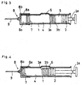
- the exemplary prefilled syringe has a generally tubular body 1 having the same diameter throughout the entire length which is open at the front and rear ends.
- the syringe is provided with another gasket, that is, a plunger 2 connectable to a push rod 2a slidably inserted into the body 1 through the rear end.
- the body 1 includes a first (front) compartment 4 and a second (rear) compartment 5 separated by a gasket 3 which consists of a front part 3a and a rear part 3b.
- the gasket 3 as a unit is slidable in and along the body 1 under pressure provided by the plunger 2.
- the first compartment 4 stores a medicinal component P (the illustrated one is in a powder form) and the second compartment 5 stores a vehicle L in a liquid or any other form for dissolving or dispersing the medicinal component P, or for becoming mixed therewith.
- the reference numeral 6 denotes a bypass in the form of an axially extending recess through which the vehicle L is introduced from the compartment 5 into the compartment 4.
- the gasket 3 and plunger 2 can be made of normal isobutylene-isoprene rubber, halogenide butylene rubber, butadiene rubber, isoprene rubber or chlorinated isobytylene-isoprene rubber or a mixture thereof.
- the front part 3a and the rear part 3b of the gasket 3 are independent of each other and separately movable.
- Each of the parts 3a and 3b extends radially to the inside wall of the body 1 to seal the rear compartment 5 from the front compartment 4.
- the combined axial length of the parts 3a and 3b is less than the axial length of the bypass 6 to permit the injection liquid to be transferred from the rear compartment 5 to the front compartment 4.
- the parts 3a and 3b are between the bypass 6 and the rear end of the tubular body 1, they preferably engage each other but they can be slightly spaced because of air being compressed therebetween. In use, as the plunger 2 is initially pushed by means of the push rod 2a, the air present between the parts 3a and 3b is compressed by the movement of the rear part 3b.
- the bypass 6 has a length longer than the total thickness of the front part 3a and the rear part 3b as shown in Figure 4. Furthermore, the combined axial length of the parts 3a, 3b, and the plunger 2 (exclusive of the push rod 2a) is greater than the axial length of the bypass 6 to prevent backflow of air or liquid from the front compartment 4 to the rear compartment 5.
- the plunger 2 is pushed to the left ( Figure 1) whereby the front part 3a and rear part 3b of the gasket 3 are moved together in a spaced apart fashion under pressure provided by the plunger 2.
- Figure 1 the parts 3a and 3b reach the bypass 6 as shown in Figure 4
- the vehicle L in the rear compartment 5 is introduced into the front compartment 4 through the bypass 6, thereby effecting a desired action such as dispersing, dissolving or mixing between the medicinal component P and the vehicle L.
- an injecting medicine or simply an injection
- the mixture in the tubular body 1 can be ejected through the injection needle 9.
- the prefilled syringe is assembled as shown in Figures 2A and 2B: Referring to Figure 2A, the rear part 3b of the gasket 3 is inserted in the body 1 and the vehicle L is put in the rear compartment 5. Then the plunger 2 is inserted.
- the vehicle L is heat sterilized by dry steam, and then the inside surface of the front compartment 4 is air-dried typically with some heat (for example, up to 50-60°C) as long as such heat does not damage the vehicle L in the rear compartment 5.
- some heat for example, up to 50-60°C
- the outer ends of the rear part 3b and plunger 2 are exposed to the dry steam and may absorb or take in moisture, which may diffuse into the rear part 3b or plunger 2. This moisture, over a period of time, may escape by diffusion or some other means out of the end of the rear part 3b or plunger 2 into which it entered. This emanating moisture will then adversely affect a hygroscopic powder contained in the front compartment 4.
- the front part 3a of the gasket 3, which is kept away from any moisture, is inserted into the body 1 through the front end 1a until it comes relatively near to or into contact with the rear part 3b so as to be adjacent thereto.
- a dose of powdery medicinal component P is placed in the front compartment 4, and then the front end 1a is closed by the plug 7. In this way a finished syringe is obtained.
- the rear part 3b of the gasket 3 becomes wet because of deposition of dew or saturated with moisture. Although most of this moisture is removed when the front compartment 4 is dried, some of it remains in the rear part 3b only to diffuse out over a period of time.
- the front part 3a is kept dry, thereby sealing the front compartment 4 against any moisture which may escape from the rear part 3b.
- the injection needle 9 can be fixed to the syringe 1 in various manners, one of the examples being shown in Figure 3:
- the example shown in Figure 3 has the front end 1a capped with a cap 8 which includes a skirt 8a carrying the injection needle 9.
- the skirt 8a includes a groove 8b on the inside surface.
- the groove 8b communicates with the needle 9.
- the reference numeral 8c denotes a space adapted to receive the plug 7 as shown in Figure 4.
- the plunger 2 When the plunger 2 is pushed to the left ( Figure 4), the plug 7 is moved into the space 8c, and the vehicle L in the rear compartment 5 is introduced into the front compartment 4 through the bypass 6.
- the injection By further pushing the plunger 2 and after the syringe is shaken or swung to mix the liquid and drug, the injection is introduced into the needle 9 through the groove 8b.
- the needle 9 may be beforehand fixed to the cap 8, or it may be fixed after the cap 8 is capped to the syringe 1.
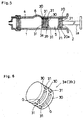
- the gasket 3 is provided with a plurality of annular ribs 30 having grooves (G) therebetween.
- the adjacent grooves (G) are bridged by other ribs 31 which will be referred to as bridging ribs.
- the bridging ribs 31 may have the same height as that of the annular ribs 30 or may have a slightly shorter height.
- the bridging ribs 31 subdivide the grooves (G) into separate small recesses.
- the illustrated part 3a and 3b have two grooves in parallel which are respectively bridged by four bridging ribs 31 displaced at 90° , thereby obtaining equally divided eight recesses in all.
- the annular ribs 30 extend at generally a right angle to the axis of the tubular body 1 and the bridging ribs 31.
- the subdividing of the grooves (G) by the bridging ribs 31 minimizes the amount of injection liquid remaining in the groove (G), thereby minimizing the amount of injection liquid which remains unused.
- the greater the number of bridging ribs which are used the less the amount of injection liquid which remains unused, but as the number of the bridging ribs increases, the friction created between the gasket 3 and the inside wall of the tubular body 1 increases, thereby preventing smooth movement of the gasket 3 in the tubular body 1.
- the bridging ribs 31 act as barriers to prevent the injection liquid from flowing circumferentially about the gasket 3. Hence a lesser quantity of injection liquid is trapped in the annular grooves (G).
- the exemplary part 3a and plunger 2 are respectively provided with annular ribs 30a, 30b, and 30c, and 20a, 20b, and 20c, with grooves 30e and 30d and 20e and 20d between the adjacent ribs. Since the part 3b has the same structure as the part 3a, the description thereof is omitted for simplicity.
- the parts 3a and the plunger 2 are fabricated such that the outside diameter of each annular rib is slightly larger than the inside diameter of the tubular body 1 when they are not encased in the body 1. When they are pressed into the container, the annular ribs sealingly engage the inside wall of the tubular body 1.
- each of the gaskets 3 and plunger 2 is provided with tapered shoulders at the right-hand sides toward the rear end of the body 1, as shown in Figures 7(A) and 7(B).
- the illustrated part 3 is thinner than the plunger 2 which may be provided with a threaded bore 20f for accepting the push rod 2a.
- seal and slidability of the gaskets are mutually contradictory; when seal is good, slidability becomes poor, and vice versa.
- Case I and Case II show situations where different containers having different inside diameters; that is, 10.5mm and 14.0mm were used.
- the "fit” is expressed in terms of a difference between the maximum outside diameter R (mm) of the part 3a (3b) and of the plunger 2 and the inside diameter r (mm) of the tubular body 1. The values are indicated by a radius portion (1/2 the value of the diameter).
- the compressibility (%) "C” is obtained by the formula (1), and the contact area (mm2) "S” of each annular rib 30 and 20 with the tubular body 1 is obtained by the following formula (2).
- the compressibility (C) is appropriately in the range of 3% to 7%
- (C X S) is appropriately in the range of 160 to 450
- (C X St) is appropriately in the range of 300 to 900.
- a group of gaskets 3 and plungers 2 (Group I) were made of normal isobutylene-isoprene rubber and a second group of them (Group II) were made of chlorinated isobutylene-isoprene rubber, both in such a manner as to satisfy the values in the prescribed ranges. Then they were encased in the tubular body 1 and sterilized by an autoclave at 121 °C for 20 minutes. The air-tightness was measured, the results of which are shown in Table 3.
- Table 3 shows the assessments in terms of ⁇ and ⁇ on seal achieved by each specimen prior to and subsequent to steam-sterilization, wherein the mark ⁇ represents "sealed", and the mark ⁇ represents "probable to leak”: TABLE 3 GROUP I GROUP II Time I II I II Specimen 1 ⁇ ⁇ ⁇ ⁇ Specimen 2 ⁇ ⁇ ⁇ ⁇ Specimen 3 ⁇ ⁇ ⁇ ⁇ Specimen 4 ⁇ ⁇ ⁇ ⁇ Specimen 5 ⁇ ⁇ ⁇ ⁇
- GROUP I The specimens in GROUP I are made of normal isobutylene-isoprene rubber, and those in GROUP II are made of chlorinated isobutylene-isoprene rubber. Time I is before sterilization, and Time II is after sterilization.
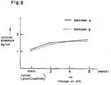
- the specimens 4 and 5 in Group II were tested at the initial pressure which was required to start the plunger 2 by means of the push rod 2a. This examination was periodically conducted for several months from the initial sterilization. The gaskets 3 and plunger 2 remained inside the tubular body 1 at 40°C through the period of examination (six months) so as to avoid any infliction of ambient influence. The results are shown in Figure 8.
- the initial pressure is expressed in Kg/cm2 in terms of force applied to a unit area of the cross-section perpendicular to the axis of the tubular body 1.
- the initial pressure was about 1 Kg/cm2 at the start, about 1.4 Kg/cm2 in two months, and finally about 1.6 to 1.7 Kg/cm2. It is noticeable that the initial pressure required increases as the storage is prolonged but it remains within the range of 1 to 2 Kg/cm2 which is not such a degree as to reduce the slidability of the specimens 4 and 5.
Landscapes
- Health & Medical Sciences (AREA)
- Vascular Medicine (AREA)
- Engineering & Computer Science (AREA)
- Anesthesiology (AREA)
- Biomedical Technology (AREA)
- Heart & Thoracic Surgery (AREA)
- Hematology (AREA)
- Life Sciences & Earth Sciences (AREA)
- Animal Behavior & Ethology (AREA)
- General Health & Medical Sciences (AREA)
- Public Health (AREA)
- Veterinary Medicine (AREA)
- Infusion, Injection, And Reservoir Apparatuses (AREA)
- Medical Preparation Storing Or Oral Administration Devices (AREA)
- Closures For Containers (AREA)
- Respiratory Apparatuses And Protective Means (AREA)
- Containers And Packaging Bodies Having A Special Means To Remove Contents (AREA)
Applications Claiming Priority (3)
| Application Number | Priority Date | Filing Date | Title |
|---|---|---|---|
| JP2148594 | 1994-02-18 | ||
| JP2148594 | 1994-02-18 | ||
| JP21485/94 | 1994-02-18 |
Publications (3)
| Publication Number | Publication Date |
|---|---|
| EP0671179A2 true EP0671179A2 (de) | 1995-09-13 |
| EP0671179A3 EP0671179A3 (de) | 1996-12-11 |
| EP0671179B1 EP0671179B1 (de) | 2003-04-09 |
Family
ID=12056284
Family Applications (1)
| Application Number | Title | Priority Date | Filing Date |
|---|---|---|---|
| EP94309914A Expired - Lifetime EP0671179B1 (de) | 1994-02-18 | 1994-12-30 | Luft- und flüssigkeitsdichter Behälter mit schiebbarer Dichtung |
Country Status (5)
| Country | Link |
|---|---|
| US (1) | US5586975A (de) |
| EP (1) | EP0671179B1 (de) |
| AT (1) | ATE236675T1 (de) |
| CA (1) | CA2139393C (de) |
| DE (1) | DE69432458T2 (de) |
Cited By (6)
| Publication number | Priority date | Publication date | Assignee | Title |
|---|---|---|---|---|
| EP0768093A1 (de) * | 1995-10-13 | 1997-04-16 | Hoechst Aktiengesellschaft | Kolben für Spritzenzylinder |
| WO1999051184A1 (en) * | 1998-04-01 | 1999-10-14 | Chienhua Tsao | Easily opened elongated tubular container |
| EP1002551A3 (de) * | 1998-11-19 | 2000-07-05 | Bracco International B.V. | Kolben- und Stangenzusammensetzung für Spritze oder Kartusche mit guter Gleitfähigkeit |
| WO2009067200A3 (en) * | 2007-11-19 | 2009-09-24 | Mallinckrodt Inc. | Fluid delivery system with multi-dose fluid source |
| WO2018157097A1 (en) * | 2017-02-27 | 2018-08-30 | W.L. Gore & Associates, Inc. | Medical delivery devices having low lubricant syringe barrels |
| US10092700B2 (en) | 2012-03-16 | 2018-10-09 | Carebay Europe Ltd | Medicament delivery device |
Families Citing this family (11)
| Publication number | Priority date | Publication date | Assignee | Title |
|---|---|---|---|---|
| WO2001087359A1 (en) * | 2000-05-16 | 2001-11-22 | Taisei Kako Co., Ltd. | Method for manufacturing sealing tool sterilized with gaseous hydrogen peroxide |
| US6511459B1 (en) | 2000-09-29 | 2003-01-28 | Mallinckrodt Inc. | Syringe plunger having an improved sealing ability |
| JP2005508231A (ja) * | 2001-11-02 | 2005-03-31 | メリディアン メディカル テクノロジーズ,インコーポレイテッド | 薬剤容器、薬剤を投与するための投薬キット、および投薬キットの包装方法 |
| US7021561B2 (en) * | 2001-12-18 | 2006-04-04 | Becton, Dickinson And Company | Spray device and method |
| CA2649559C (en) * | 2006-04-21 | 2014-07-29 | Arzneimittel Gmbh Apotheker Vetter & Co. Ravensburg | Syringe cylinder |
| KR101439466B1 (ko) * | 2007-11-08 | 2014-09-15 | 주식회사 엘지생명과학 | 약물 주사 장치 및 약물 주사용 키트 |
| US8406510B2 (en) * | 2010-03-10 | 2013-03-26 | Industrial Technology Research Institute | Methods for evaluating distances in a scene and apparatus and machine readable medium using the same |
| JP7066411B2 (ja) * | 2015-02-20 | 2022-05-13 | リジェネロン・ファーマシューティカルズ・インコーポレイテッド | シリンジシステム、ピストンシールシステム、ストッパシステム、並びに使用及び組み立て方法 |
| CN107089441B (zh) * | 2017-06-13 | 2020-06-02 | 苏州中科生物医用材料有限公司 | 一种软骨修复器械 |
| JP2021514781A (ja) * | 2018-03-06 | 2021-06-17 | ダブリュ.エル.ゴア アンド アソシエイツ,インコーポレイティドW.L. Gore & Associates, Incorporated | 低潤滑剤疎水性シリンジバレルを有するメディカルデリバリーデバイス |
| CA3245409A1 (en) * | 2022-03-04 | 2023-09-07 | Sio2 Medical Products, Inc. | LOW-FRICTION, OIL-FREE SYRINGE PISTON FEEDING TUBES AND THEIR METHODS OF USE FOR FEEDING PISTONS IN SYRINGES |
Family Cites Families (35)
| Publication number | Priority date | Publication date | Assignee | Title |
|---|---|---|---|---|
| US1961023A (en) * | 1933-12-07 | 1934-05-29 | Herman O West | Plunger for hypodermic syringes |
| GB705392A (en) * | 1951-03-14 | 1954-03-10 | Frank Myles Turnbull | Improvements relating to hypodermic injection apparatus |
| US2688967A (en) * | 1953-06-02 | 1954-09-14 | Huber Jennie | Metal aspirating syringe |
| US3330282A (en) * | 1964-08-21 | 1967-07-11 | Upjohn Co | Combination syringe and vial mixing container |
| DE1616199A1 (de) * | 1968-01-22 | 1972-05-10 | Uwe Jacobsen | Zweikammer-Spritzampulle |
| US3766918A (en) * | 1971-09-07 | 1973-10-23 | J Kessel | Self-aspirating hypodermic ampule |
| US3967759A (en) * | 1971-11-11 | 1976-07-06 | Mpl, Inc. | Syringe assembly with contained pop-out elastic plug seal |
| US3729031A (en) * | 1971-12-06 | 1973-04-24 | Mpl Inc | Liquid dispenser and plunger and method and apparatus for filling same |
| US3807119A (en) * | 1972-06-21 | 1974-04-30 | W Shields | Method of assembling a multiple compartment hypodermic syringe |
| US3946732A (en) * | 1973-08-08 | 1976-03-30 | Ampoules, Inc. | Two-chamber mixing syringe |
| US3831601A (en) * | 1973-10-29 | 1974-08-27 | Rohe Scientific Corp | Adjustable syringe plunger |
| AT341649B (de) * | 1975-08-07 | 1978-02-27 | Immuno Ag | Injektionsspritze |
| NL180634C (nl) * | 1977-12-23 | 1987-04-01 | Duphar Int Res | Injectiespuit alsmede naaldhouder hiervoor. |
| JPS5918427B2 (ja) * | 1979-10-09 | 1984-04-27 | テルモ株式会社 | シリンジ用ガスケツト |
| EP0072058A1 (de) * | 1981-08-10 | 1983-02-16 | Duphar International Research B.V | Spritze mit mehrereren Kammern |
| US4424057A (en) * | 1982-04-01 | 1984-01-03 | House Hugh A | Wet-dry syringe |
| US4439184A (en) * | 1982-05-03 | 1984-03-27 | Concord Laboratories, Inc. | Two-dose syringe |
| FR2547201A1 (fr) * | 1983-06-08 | 1984-12-14 | Villette Alain | Piston de cartouche d'anesthesique |
| US4599082A (en) * | 1984-08-13 | 1986-07-08 | Becton, Dickinson And Company | Two-component syringe assembly |
| ATE42041T1 (de) * | 1985-02-07 | 1989-04-15 | Duphar Int Res | Injektionsspritze. |
| EP0207544B1 (de) * | 1985-06-27 | 1990-09-26 | Duphar International Research B.V | Mehrkammerspritze |
| US4613326A (en) * | 1985-07-12 | 1986-09-23 | Becton, Dickinson And Company | Two-component medication syringe assembly |
| DE3673317D1 (de) * | 1985-10-11 | 1990-09-13 | Duphar Int Res | Automatische spritze. |
| ES2024489B3 (es) * | 1986-05-15 | 1992-03-01 | Duphar Int Res B V | Inyector automatico. |
| JPH0747045B2 (ja) * | 1986-10-15 | 1995-05-24 | 株式会社大協精工 | 積層した注射器用滑栓 |
| IL86799A (en) * | 1987-07-02 | 1993-03-15 | Kabi Pharmacia Ab | Method and device for injection |
| GB8723454D0 (en) * | 1987-10-06 | 1987-11-11 | Beecham Group Plc | Device |
| EP0328699B1 (de) * | 1988-02-16 | 1991-09-18 | Arzneimittel GmbH Apotheker Vetter & Co. Ravensburg | Spritze für medizinische Zwecke |
| NL8802106A (nl) * | 1988-08-26 | 1990-03-16 | Abraham Van Den Haak | Naaldbeveiliging voor een injectiespuit. |
| DE69000716T2 (de) * | 1989-03-28 | 1993-07-22 | Duphar Int Res | Vorgefuellte injektionsvorrichtung mit einem fass, das mit einer fluessigen diazepam-formulierung gefuellt ist. |
| DE3916101A1 (de) * | 1989-05-17 | 1990-11-22 | Vetter & Co Apotheker | Spritze fuer medizinische zwecke |
| DE3924830A1 (de) * | 1989-07-27 | 1991-02-07 | Vetter & Co Apotheker | Spritzenzylinder fuer medizinische zwecke |
| DK0440846T3 (da) * | 1990-02-07 | 1993-07-12 | Vetter & Co Apotheker | Dobbeltkammersprøjte og anvendelsesfremgangsmåde |
| FR2672868B1 (fr) * | 1991-02-15 | 1993-06-04 | Pasteur Merieux Serums Vacc | Procede de conditionnement de vaccins lyophilises en seringue et bouchon pour sa mise en óoeuvre. |
| IL105396A (en) * | 1992-04-30 | 1998-02-22 | Takeda Chemical Industries Ltd | Prefilled syringe |
-
1994
- 1994-12-29 US US08/365,947 patent/US5586975A/en not_active Expired - Lifetime
- 1994-12-30 CA CA002139393A patent/CA2139393C/en not_active Expired - Lifetime
- 1994-12-30 EP EP94309914A patent/EP0671179B1/de not_active Expired - Lifetime
- 1994-12-30 DE DE69432458T patent/DE69432458T2/de not_active Expired - Lifetime
- 1994-12-30 AT AT94309914T patent/ATE236675T1/de not_active IP Right Cessation
Cited By (14)
| Publication number | Priority date | Publication date | Assignee | Title |
|---|---|---|---|---|
| EP0768093A1 (de) * | 1995-10-13 | 1997-04-16 | Hoechst Aktiengesellschaft | Kolben für Spritzenzylinder |
| WO1999051184A1 (en) * | 1998-04-01 | 1999-10-14 | Chienhua Tsao | Easily opened elongated tubular container |
| EP1002551A3 (de) * | 1998-11-19 | 2000-07-05 | Bracco International B.V. | Kolben- und Stangenzusammensetzung für Spritze oder Kartusche mit guter Gleitfähigkeit |
| WO2009067200A3 (en) * | 2007-11-19 | 2009-09-24 | Mallinckrodt Inc. | Fluid delivery system with multi-dose fluid source |
| US10092700B2 (en) | 2012-03-16 | 2018-10-09 | Carebay Europe Ltd | Medicament delivery device |
| US10493207B2 (en) | 2017-02-27 | 2019-12-03 | W. L. Gore & Associates, Inc. | Medical delivery devices having low lubricant syringe barrels |
| WO2018157097A1 (en) * | 2017-02-27 | 2018-08-30 | W.L. Gore & Associates, Inc. | Medical delivery devices having low lubricant syringe barrels |
| EP3597243A1 (de) * | 2017-02-27 | 2020-01-22 | W. L. Gore & Associates Inc | Medizinische abgabevorrichtungen mit schmierstoffarmen spritzenzylindern |
| AU2018224299B2 (en) * | 2017-02-27 | 2020-04-16 | W.L. Gore & Associates, Inc. | Medical delivery devices having low lubricant syringe barrels |
| AU2020202193B2 (en) * | 2017-02-27 | 2020-11-05 | W.L. Gore & Associates, Inc. | Medical delivery devices having low lubricant syringe barrels |
| AU2020205288B2 (en) * | 2017-02-27 | 2021-10-14 | W.L. Gore & Associates, Inc. | Medical delivery devices having low lubricant syringe barrels |
| AU2022200248B2 (en) * | 2017-02-27 | 2023-08-03 | W. L. Gore & Associates, Inc. | Medical delivery devices having low lubricant syringe barrels |
| EP4252788A3 (de) * | 2017-02-27 | 2023-12-06 | W. L. Gore & Associates, Inc. | Medizinische abgabevorrichtungen mit schmierstoffarmen spritzenzylindern |
| US11931553B2 (en) | 2017-02-27 | 2024-03-19 | W. L. Gore & Associates, Inc. | Medical delivery devices having low lubricant syringe barrels |
Also Published As
| Publication number | Publication date |
|---|---|
| DE69432458T2 (de) | 2004-02-26 |
| EP0671179B1 (de) | 2003-04-09 |
| CA2139393A1 (en) | 1995-08-19 |
| EP0671179A3 (de) | 1996-12-11 |
| US5586975A (en) | 1996-12-24 |
| ATE236675T1 (de) | 2003-04-15 |
| CA2139393C (en) | 2006-08-29 |
| DE69432458D1 (de) | 2003-05-15 |
Similar Documents
| Publication | Publication Date | Title |
|---|---|---|
| EP0671179B1 (de) | Luft- und flüssigkeitsdichter Behälter mit schiebbarer Dichtung | |
| EP0511402B1 (de) | Spritzenzylinder mit zwei kammern | |
| DE69508629T2 (de) | Spritze und Verfahren zur Lyophilisierung und Wiederherstellung von einspritzbaren Medikamenten | |
| US5716339A (en) | Prefilled syringe | |
| EP0664136B1 (de) | Ein trockenes Medikament enthaltende und dessen Rekonstitution und Injektion ermöglichende Spritze | |
| US5139490A (en) | Hypodermic syringe | |
| US4254768A (en) | Hypodermic syringe | |
| CA2118034C (en) | Injection cartridge arrangement | |
| US4668223A (en) | Syringe | |
| US4698055A (en) | Hypodermic syringe | |
| CA2105603C (en) | Syringe having needle isolation features | |
| EP0639991B1 (de) | Injektionsbehälter | |
| EP0915711B1 (de) | Verfahren zur terminalen sterilisierung von befüllten spritzen bei stützdruck | |
| JPS59115053A (ja) | 注射器用プランジヤ−ロツド組立体 | |
| US4245654A (en) | Blood sampling syringe | |
| US4041945A (en) | Mixing syringe | |
| US4113097A (en) | Ampule capable of being autoclaved | |
| JP3009598B2 (ja) | プレフィルドシリンジ | |
| JP4481416B2 (ja) | プレフィルドシリンジ | |
| US4212307A (en) | Blood sampling syringe | |
| WO1998017338A1 (de) | Vorgefüllte, sterile spritzen mit spritzenstopfen aus polyethylen | |
| JP2006212386A (ja) | プレフィルドシリンジの収容物充填方法 | |
| CA1091117A (en) | Blood sampling syringe | |
| CA2057015A1 (en) | Device and method for avoiding contamination of multi-dose medicament vials |
Legal Events
| Date | Code | Title | Description |
|---|---|---|---|
| PUAI | Public reference made under article 153(3) epc to a published international application that has entered the european phase |
Free format text: ORIGINAL CODE: 0009012 |
|
| AK | Designated contracting states |
Kind code of ref document: A2 Designated state(s): AT BE CH DE DK ES FR GB GR IE IT LI LU NL PT SE |
|
| PUAL | Search report despatched |
Free format text: ORIGINAL CODE: 0009013 |
|
| AK | Designated contracting states |
Kind code of ref document: A3 Designated state(s): AT BE CH DE DK ES FR GB GR IE IT LI LU NL PT SE |
|
| 17P | Request for examination filed |
Effective date: 19970513 |
|
| 17Q | First examination report despatched |
Effective date: 19990830 |
|
| GRAG | Despatch of communication of intention to grant |
Free format text: ORIGINAL CODE: EPIDOS AGRA |
|
| GRAG | Despatch of communication of intention to grant |
Free format text: ORIGINAL CODE: EPIDOS AGRA |
|
| GRAG | Despatch of communication of intention to grant |
Free format text: ORIGINAL CODE: EPIDOS AGRA |
|
| GRAH | Despatch of communication of intention to grant a patent |
Free format text: ORIGINAL CODE: EPIDOS IGRA |
|
| GRAH | Despatch of communication of intention to grant a patent |
Free format text: ORIGINAL CODE: EPIDOS IGRA |
|
| GRAA | (expected) grant |
Free format text: ORIGINAL CODE: 0009210 |
|
| AK | Designated contracting states |
Designated state(s): AT BE CH DE DK ES FR GB GR IE IT LI LU NL PT SE |
|
| PG25 | Lapsed in a contracting state [announced via postgrant information from national office to epo] |
Ref country code: NL Free format text: LAPSE BECAUSE OF FAILURE TO SUBMIT A TRANSLATION OF THE DESCRIPTION OR TO PAY THE FEE WITHIN THE PRESCRIBED TIME-LIMIT Effective date: 20030409 Ref country code: BE Free format text: LAPSE BECAUSE OF FAILURE TO SUBMIT A TRANSLATION OF THE DESCRIPTION OR TO PAY THE FEE WITHIN THE PRESCRIBED TIME-LIMIT Effective date: 20030409 Ref country code: AT Free format text: LAPSE BECAUSE OF FAILURE TO SUBMIT A TRANSLATION OF THE DESCRIPTION OR TO PAY THE FEE WITHIN THE PRESCRIBED TIME-LIMIT Effective date: 20030409 |
|
| REG | Reference to a national code |
Ref country code: GB Ref legal event code: FG4D |
|
| REG | Reference to a national code |
Ref country code: CH Ref legal event code: EP |
|
| REG | Reference to a national code |
Ref country code: IE Ref legal event code: FG4D |
|
| PG25 | Lapsed in a contracting state [announced via postgrant information from national office to epo] |
Ref country code: SE Free format text: LAPSE BECAUSE OF FAILURE TO SUBMIT A TRANSLATION OF THE DESCRIPTION OR TO PAY THE FEE WITHIN THE PRESCRIBED TIME-LIMIT Effective date: 20030709 Ref country code: PT Free format text: LAPSE BECAUSE OF FAILURE TO SUBMIT A TRANSLATION OF THE DESCRIPTION OR TO PAY THE FEE WITHIN THE PRESCRIBED TIME-LIMIT Effective date: 20030709 Ref country code: GR Free format text: LAPSE BECAUSE OF FAILURE TO SUBMIT A TRANSLATION OF THE DESCRIPTION OR TO PAY THE FEE WITHIN THE PRESCRIBED TIME-LIMIT Effective date: 20030709 Ref country code: DK Free format text: LAPSE BECAUSE OF FAILURE TO SUBMIT A TRANSLATION OF THE DESCRIPTION OR TO PAY THE FEE WITHIN THE PRESCRIBED TIME-LIMIT Effective date: 20030709 |
|
| REG | Reference to a national code |
Ref country code: CH Ref legal event code: NV Representative=s name: ARNOLD & SIEDSMA AG |
|
| NLV1 | Nl: lapsed or annulled due to failure to fulfill the requirements of art. 29p and 29m of the patents act | ||
| PG25 | Lapsed in a contracting state [announced via postgrant information from national office to epo] |
Ref country code: ES Free format text: LAPSE BECAUSE OF FAILURE TO SUBMIT A TRANSLATION OF THE DESCRIPTION OR TO PAY THE FEE WITHIN THE PRESCRIBED TIME-LIMIT Effective date: 20031030 |
|
| PG25 | Lapsed in a contracting state [announced via postgrant information from national office to epo] |
Ref country code: LU Free format text: LAPSE BECAUSE OF NON-PAYMENT OF DUE FEES Effective date: 20031230 Ref country code: IE Free format text: LAPSE BECAUSE OF NON-PAYMENT OF DUE FEES Effective date: 20031230 |
|
| ET | Fr: translation filed | ||
| PLBE | No opposition filed within time limit |
Free format text: ORIGINAL CODE: 0009261 |
|
| STAA | Information on the status of an ep patent application or granted ep patent |
Free format text: STATUS: NO OPPOSITION FILED WITHIN TIME LIMIT |
|
| 26N | No opposition filed |
Effective date: 20040112 |
|
| REG | Reference to a national code |
Ref country code: IE Ref legal event code: MM4A |
|
| REG | Reference to a national code |
Ref country code: CH Ref legal event code: PFA Owner name: ARTE CORPORATION Free format text: TAKEDA CHEMICAL INDUSTRIES, LTD.#1-1, DOSHOMACHI 4-CHOME#CHUO-KU, OSAKA 541 (JP) $ ARTE CORPORATION#5-8 IWAMOTOCHO 1-CHOME#CHIYODA-KU, TOKYO 101 (JP) -TRANSFER TO- ARTE CORPORATION#5-8 IWAMOTOCHO 1-CHOME#CHIYODA-KU, TOKYO 101 (JP) $ TAKEDA PHARMACEUTICAL COMPANY LIMITED#1-1, DOSHOMACHI 4-CHOME CHUO-KU#OSAKA (JP) |
|
| REG | Reference to a national code |
Ref country code: FR Ref legal event code: CD |
|
| REG | Reference to a national code |
Ref country code: CH Ref legal event code: PFA Owner name: ARTE CORPORATION Free format text: ARTE CORPORATION#5-8 IWAMOTOCHO 1-CHOME#CHIYODA-KU, TOKYO 101 (JP) $ TAKEDA PHARMACEUTICAL COMPANY LIMITED#1-1, DOSHOMACHI 4-CHOME CHUO-KU#OSAKA (JP) -TRANSFER TO- ARTE CORPORATION#5-8 IWAMOTOCHO 1-CHOME#CHIYODA-KU, TOKYO 101 (JP) $ TAKEDA PHARMACEUTICAL COMPANY LIMITED#1-1, DOSHOMACHI 4-CHOME CHUO-KU#OSAKA (JP) |
|
| PGFP | Annual fee paid to national office [announced via postgrant information from national office to epo] |
Ref country code: GB Payment date: 20131227 Year of fee payment: 20 Ref country code: DE Payment date: 20131224 Year of fee payment: 20 Ref country code: CH Payment date: 20131212 Year of fee payment: 20 |
|
| PGFP | Annual fee paid to national office [announced via postgrant information from national office to epo] |
Ref country code: FR Payment date: 20131209 Year of fee payment: 20 Ref country code: IT Payment date: 20131212 Year of fee payment: 20 |
|
| REG | Reference to a national code |
Ref country code: DE Ref legal event code: R071 Ref document number: 69432458 Country of ref document: DE |
|
| REG | Reference to a national code |
Ref country code: DE Ref legal event code: R071 Ref document number: 69432458 Country of ref document: DE |
|
| REG | Reference to a national code |
Ref country code: GB Ref legal event code: PE20 Expiry date: 20141229 |
|
| REG | Reference to a national code |
Ref country code: CH Ref legal event code: PL |
|
| PG25 | Lapsed in a contracting state [announced via postgrant information from national office to epo] |
Ref country code: GB Free format text: LAPSE BECAUSE OF EXPIRATION OF PROTECTION Effective date: 20141229 |