EP0671508A2 - Pavé - Google Patents
Pavé Download PDFInfo
- Publication number
- EP0671508A2 EP0671508A2 EP95103121A EP95103121A EP0671508A2 EP 0671508 A2 EP0671508 A2 EP 0671508A2 EP 95103121 A EP95103121 A EP 95103121A EP 95103121 A EP95103121 A EP 95103121A EP 0671508 A2 EP0671508 A2 EP 0671508A2
- Authority
- EP
- European Patent Office
- Prior art keywords
- blocks
- plates
- patch according
- tie rods
- corners
- Prior art date
- Legal status (The legal status is an assumption and is not a legal conclusion. Google has not performed a legal analysis and makes no representation as to the accuracy of the status listed.)
- Granted
Links
Images


Classifications
-
- E—FIXED CONSTRUCTIONS
- E01—CONSTRUCTION OF ROADS, RAILWAYS, OR BRIDGES
- E01C—CONSTRUCTION OF, OR SURFACES FOR, ROADS, SPORTS GROUNDS, OR THE LIKE; MACHINES OR AUXILIARY TOOLS FOR CONSTRUCTION OR REPAIR
- E01C5/00—Pavings made of prefabricated single units
- E01C5/005—Individual couplings or spacer elements for joining the prefabricated units
Definitions
- the invention relates to a plaster of blocks or slabs which are laid with a spacing between the joints.
- the paving stones and paving slabs made of concrete with molded spacers which have become known in recent times, have direct contact with one another through this. But they are also held by a joint filling.
- the joint filling originally made of sand, solidifies over time through the ingress of dust, etc.
- Such a paving compound is more resistant to horizontal forces, such as those exerted by starting or braking motor vehicles, due to the direct contact.
- the invention has for its object to further increase the resistance of the patch.
- this purpose is achieved in that the blocks or plates are further connected to one another by tie rods which have recesses in the blocks or plates fitted in them from the surface thereof.
- the tie rods not only absorb any horizontal tensile forces that arise, but also vertical ones. If, according to an advantageous embodiment of the invention, they extend somewhat clampingly through the entire depth or at least half the depth of the blocks or stones, they even create a rigid connection prevents a block or plate from lifting on one side alone.
- the pavement is also secured in the vertical direction.
- the spacers mentioned at the outset can furthermore be integrally formed on the blocks or stones or inserted separately in the joints.
- the tie rods can also serve as spacers or be provided with such.
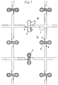
- FIGS. 1 to 15 each show the exemplary embodiments in a top view of the plaster, partly in an exploded isometric view.
- a first and particularly essential embodiment shown in FIGS. 1 to 9 is characterized in that the recesses are from the side surfaces, as in FIGS. 1 to 7, or from the corners, as in FIGS. 8 to 9 Extend the undercut into the blocks or plates and extend from the surface of the blocks or plates with a substantially constant cross-section.
- a plaster of blocks or slabs 2 laid with joints 1, for example made of concrete, can be seen.
- the blocks or plates 2 are provided on each edge in the middle with a recess 3, which extends from the side surface first with a rectangular cross-sectional section 4 and then with an approximately circular cross-sectional section 5 into the material.
- the recesses 3 are formed continuously from the surface to the underside of the blocks or plates 2.
- Two recesses 3 are drawn empty in Fig. 1 above.
- Tie rods 6 are inserted into the other recesses 3 from above. For example, they are made of plastic and are hammered in. They are designed to be complementary to the cross section of the recesses 3 and also fill them in their full height.
- a spacer 7 is formed on the side surface of the block or plate, which defines the joint width.
- the tie rods 6 are in this arrangement in a visible interplay with the spacers 7 consisting of the pressure-resistant material of the blocks or plates 2 as possibly pressure-absorbing elements. A filling of sand, not shown, is introduced into the joints 1.
- the blocks and plates 8 have no spacers 7. Instead, the tie rods 9 are provided with spacers 10. They branch off on both sides of the section of the tie rod 9 lying in the joint.
- the tie rods 11 also have the function of the spacers.
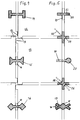
- Fig. 4 shows a form of blocks or plates 12, each having a molded spacer 13 projecting with the joint width at the end of the side surface, so that there is a circumferential support at the joint crossings and the cross joint is interrupted.
- various variants of the recess and the tie rod cross-section following the rectangular cross-sectional section 4 are shown, namely a cross-shaped rectangular cross-sectional section 14, an approximately trapezoidal cross-sectional section 15 and an approximately check-shaped cross-sectional section 16 Spacer 10.
- Fig. 5 shows further variations of recesses and tie rods as well as spacers.
- the undercut by which the tie rod 17 is held is formed by a branch 18 of the cross section of the recess.
- the recess was not created when the stone was formed, but was subsequently cut into an X-shape, preferably at an angle of 30 °.
- a tie rod 20 is shown molded into one block or plate at 19.
- the blocks or plates can always have the tie rods 20 on two adjacent side surfaces and the recesses 3 on the other two adjacent side surfaces. 5 shows various spacers neither molded onto the blocks or plates nor onto the tie rods.
- a web-shaped spacer 21 is shown at the top, which projects into two incisions 22 of the blocks or plates.
- the other arrangement of the same web-shaped spacer is indicated by dashed lines at 23, simply as an insert in the joint or as a branching off of transverse webs on the spacer 21.
- the cross-shaped spacer is here divided into two diagonally colliding, angular spacers 26, each anchored to a block or a plate.
- Fig. 6 shows isometrically on the left the tie rod 6 with the same height as the blocks or plates 2 and on the right the recess 3 with half this height. The same applies accordingly in FIG. 7 on the left for the tie rod with trapezoidal cross-sectional section 15 and branching spacers 10 and on the right for the tie rod with transverse rectangular cross-sectional section 14.
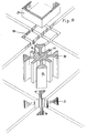
- FIG. 8 to 10 show corner arrangements of the tie rods.
- the crossed tie rods 27 in FIG. 8 at the top right correspond to the arrangement of the tie rods 11 in FIG. 2 on the sides.
- the same crossed tie rods 27 can be seen in FIG. 8 at the top left.
- they are not directly in recesses in the concrete, but in hollow profile parts 28, for example made of cast iron, molded into the blocks or plates.
- Dashed lines indicate a spacer 29 instead inserted at this corner with the cross-section of a hollow check and webs 30 extending from the corners thereof into the joints beveled edges of the blocks or panels.
- the latter function alone is shown in Fig. 8 bottom left with the modification that the spacer 31 there has a ring cross-section.
- tie rods 36 arranged at the corners start from a central body 37, which is at the same time a spacer as a result of abutment on the chamfered corners 38 of the blocks or plates, which are somewhat pulled out here. This corresponds to the spacer 31 with the additions 34 to the tie rod.
- Fig. 9 also shows on the right tie rods 39, which emanate from a full, square-shaped central body 40, which itself is a spacer by abutting the chamfered corners of the blocks or plates, but also has spacing webs 41 protruding into the joints.
- the same arrangement is shown in FIG. 13 below in an isometric representation.
- a combination 42 of tie rod and spacer, which is also to be described, but of a different cross-sectional shape, is shown on the left in FIG. 9.
- the tie rod is in turn seated in the hollow profile parts 43 molded into the blocks or plates.
- These hollow profile parts 43 could be sections of an extruded plastic profile.
- the production the blocks or slabs could be made on the way via large-volume blocks into which the plastic profiles are molded and which are then cut into the blocks or slabs of the plaster.
- the recesses 3 could also be produced by molded tubes which form the circular cross-sectional section 5 and by later cutting the rectangular cross-sectional sections 4, preferably before the large-volume blocks are cut into the blocks or slabs of the plaster.
- FIG. 10 shows a modification: the recesses here are bare cuts 44 of rectangular cross section arranged from the side near the corners of the blocks or plates, and between four adjacent corners of different blocks or plates used tie rods 45 extend into the four joints and from these into a T-shape in the mutually opposite incisions 44, such that they grip each corner in a hook shape in two such incisions with the T-bars 46.
- the corners 47 of the blocks or plates are rounded, the tie rods 45 are connected in an arc shape following the curves.
- the recesses are cuts 48 of rectangular cross-section at the corners of the blocks or plates from above, such that the cuts 48 of four adjacent corners of different blocks or plates complement one another in an annular manner to accommodate an annular tie rod.
- the tie rod 49 is a circular ring.
- the tie rod 50 has the shape of a check.
- the tie rod 51 has the shape of a square. (In the present application, a distinction is made between square and diamond in terms of position.) The same arrangement is shown in an isometric representation in FIG. 13 above.
- the tie rod 52 also has the shape of a square. Spacers 13, enclosed by the square, are arranged at the corners of the blocks or plates in the configuration described in relation to FIG. 4.
- annular tie rods 49 to 51 in particular the square tie rod 51, in their incisions 48 also allows the absorption of compressive forces. Without additional spacers as in Fig. 12 bottom right, these tie rods 49 to 51 will be made of steel.
- the annular tie rod 52 according to FIG. 11 could be made of plastic. It does not need to absorb compressive forces in the ring, since it is provided with spacers 53 and a central body 54 arranged in the manner of spokes, which lie in the joints and the joint crossing.
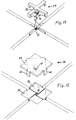
- FIGS. 14 and 15 Again a new variant of the recess and tie rod and the engagement of the tie rod are shown in FIGS. 14 and 15 in an isometric view.
- the blocks or plates have spacers 13 formed near their ends, each projecting into the joint on one side, in the configuration already known and described in plan view from FIG. 4. Above the spacers 13, however, the flat recess 55 or 56 is arranged, into which the tie rod 57 or 58, which bridges the four corners, is inserted.
- the tie rod 57 in FIG. 14 the bridging has the shape of a cross 59 lying in the alignment of the joints.
- the tie rod 58 in FIG. 15 it has the shape of a plate 60 which extends beyond it.
- fingers 61 angled like a staple grasp each in the joints behind a spacer 13.
- a bolt 62 arranged centrally under the cross 59 or the plate 60 also fits into the gap 63 between the four spacers 13.
- the bolt 62 has an annular profile 64 from barbed cross section of the rings. It can e.g. be applied by a rubber covering.
- the entire bolt 62 is made of a similarly soft material and, not shown, is screwed to the cross 59 or the plate 60.
- the bolt 62 can also be inserted first, for example driven in, and then the remaining tie rod can be placed and held by the screw connection with the bolt.
- Similar tie rods could also grip fingers or angled fingers bridging from adjacent blocks or plates at the sides or corners in these adapted recesses in the recesses of the blocks or plates receiving the tie rods. Spacers molded onto the blocks or plates could also be present.
- the recesses extend from the sides or corners in principle without undercut into the blocks or plates and from the surface of the blocks or plates made with a substantially constant cross-section, and in this case clamp the tie rods in the recesses.
- tie rods are then expediently strong blocks made of a harder rubber with a barb profile on their clamping surfaces. They can be hammered into the recesses.
- the other tie rods consist, for example, of steel or other metal, wood, plastic, in particular recycled plastic, or also of rubber.
- Concrete is primarily used for the blocks or slabs, but by no means exclusively. Likewise possible are e.g. ceramic material or recycled plastic.
Landscapes
- Engineering & Computer Science (AREA)
- Architecture (AREA)
- Civil Engineering (AREA)
- Structural Engineering (AREA)
- Road Paving Structures (AREA)
- Polishing Bodies And Polishing Tools (AREA)
- Revetment (AREA)
Applications Claiming Priority (2)
| Application Number | Priority Date | Filing Date | Title |
|---|---|---|---|
| DE9403780U DE9403780U1 (de) | 1994-03-07 | 1994-03-07 | Pflaster |
| DE9403780U | 1994-03-07 |
Publications (3)
| Publication Number | Publication Date |
|---|---|
| EP0671508A2 true EP0671508A2 (fr) | 1995-09-13 |
| EP0671508A3 EP0671508A3 (fr) | 1995-10-25 |
| EP0671508B1 EP0671508B1 (fr) | 2003-09-24 |
Family
ID=6905578
Family Applications (1)
| Application Number | Title | Priority Date | Filing Date |
|---|---|---|---|
| EP95103121A Expired - Lifetime EP0671508B1 (fr) | 1994-03-07 | 1995-03-04 | Pavé |
Country Status (3)
| Country | Link |
|---|---|
| EP (1) | EP0671508B1 (fr) |
| AT (1) | ATE250693T1 (fr) |
| DE (3) | DE9403780U1 (fr) |
Cited By (3)
| Publication number | Priority date | Publication date | Assignee | Title |
|---|---|---|---|---|
| EP1431458A2 (fr) | 2002-12-16 | 2004-06-23 | Petec Société Anonyme | Dispositif de fixation de la structure d'un pavement composé de dalles |
| ES2325710A1 (es) * | 2007-03-29 | 2009-09-14 | Promociones Brial, S.L. | Suelo desmontable. |
| US7958688B2 (en) | 2007-03-29 | 2011-06-14 | Promociones Brial, S.L. | Assembly system for floor and/or wall tiles |
Families Citing this family (6)
| Publication number | Priority date | Publication date | Assignee | Title |
|---|---|---|---|---|
| DE19600318C1 (de) * | 1996-01-08 | 1997-04-30 | Gerd Franz Knoebel | Bodenbelag |
| FI103524B1 (fi) * | 1997-04-16 | 1999-07-15 | Variform Oy | Liitosjärjestely |
| DE102010061473A1 (de) * | 2010-12-22 | 2012-06-28 | Bte Stelcon Deutschland Gmbh | Platte, Plattenaggregat und Verfahren zur Verlegung eines Plattenaggregates |
| DE102016111828A1 (de) * | 2016-06-28 | 2017-12-28 | Metten Stein + Design Gmbh & Co. Kg | System und Verfahren zum Verlegen von Platten auf einer Unterlage |
| FR3106601B1 (fr) * | 2020-01-23 | 2025-02-28 | Molas Sebastien | Dalle de revêtement de surface de voirie |
| WO2023007226A1 (fr) * | 2021-07-29 | 2023-02-02 | Purple Alternative Surface | Dalle de revêtement de surface de voirie |
Family Cites Families (15)
| Publication number | Priority date | Publication date | Assignee | Title |
|---|---|---|---|---|
| US1469939A (en) * | 1919-10-27 | 1923-10-09 | Herbert M Knight | Highway construction |
| DE1534368A1 (de) * | 1966-06-15 | 1969-05-29 | Rohling Dipl Ing Konrad | Fahrbahndecke aus vorgefertigten Platten |
| DE1960736U (de) * | 1967-03-02 | 1967-05-24 | Ferma Werke Fertigbau Und Masc | Verbundstein. |
| DE7138979U (de) * | 1971-10-15 | 1972-05-18 | Michels H | Perforierte Kunststoffplatten zum Einlegen und Einfassen von Wegen und Plätzen und Befestigungsplatten, deren Seitenkanten so geformt sind, daß eine feste Verzahnung erfolgen kann |
| DE2733311A1 (de) * | 1977-07-23 | 1979-02-08 | Reifen Weiss Kg | Platte zum herstellen eines bodenbelages aus elastischem material |
| CH642701A5 (de) * | 1979-09-03 | 1984-04-30 | Willi Ruckstuhl | Fahrbahndecke aus einzelnen, miteinander verbundenen elementen. |
| DE3118487A1 (de) * | 1981-05-09 | 1982-11-25 | Reinhard 7500 Karlsruhe Juraschek | Verbundsystem zum errichten von abgrenzungen und verbundstein fuer dieses system |
| US4430837A (en) * | 1981-11-16 | 1984-02-14 | Bell Telephone Laboratories, Incorporated | Fastening arrangement for abutting structural members |
| US4474504A (en) * | 1983-04-20 | 1984-10-02 | Columbia Building Materials, Inc. | Underwater erosion control system having primary elements including truncated conical recesses for receiving articulated interconnect links |
| FR2554521B1 (fr) * | 1983-11-07 | 1987-05-15 | Schouvey Jean Claude | Dispositif d'assemblage demontable integre et fonctionnel de tapis a us |
| DE3605959A1 (de) * | 1986-01-08 | 1987-07-09 | Mielke Horst Guenter | Verbundplatte zur verringerung des regenabflusses von wegen und plaetzen in die kanalisation |
| DE3841656A1 (de) * | 1988-12-10 | 1990-08-09 | Spiess Kunststoff Recycling | Doppelseitig verlegbare gitterplatte aus kunststoff, insbesondere aus recycling - kunststoff |
| AT398996B (de) * | 1988-12-28 | 1995-02-27 | Schmaranz Ing Rudolf | Bodenstein |
| EP0428762B1 (fr) * | 1989-11-17 | 1993-07-28 | Peter Geiger | Elément de pavage en forme de plaque |
| DE9101959U1 (de) * | 1991-02-20 | 1991-07-04 | Philipp, Klaus Ulrich, 5920 Bad Berleburg | Bodenbelag |
-
1994
- 1994-03-07 DE DE9403780U patent/DE9403780U1/de not_active Expired - Lifetime
- 1994-04-25 DE DE4414341A patent/DE4414341A1/de not_active Withdrawn
-
1995
- 1995-03-04 EP EP95103121A patent/EP0671508B1/fr not_active Expired - Lifetime
- 1995-03-04 DE DE59510797T patent/DE59510797D1/de not_active Expired - Lifetime
- 1995-03-04 AT AT95103121T patent/ATE250693T1/de active
Cited By (4)
| Publication number | Priority date | Publication date | Assignee | Title |
|---|---|---|---|---|
| EP1431458A2 (fr) | 2002-12-16 | 2004-06-23 | Petec Société Anonyme | Dispositif de fixation de la structure d'un pavement composé de dalles |
| DE10258591B4 (de) * | 2002-12-16 | 2010-03-04 | Petec S.A. | Vorrichtung zum Festigen der Struktur eines Platten bestehenden Pflasters |
| ES2325710A1 (es) * | 2007-03-29 | 2009-09-14 | Promociones Brial, S.L. | Suelo desmontable. |
| US7958688B2 (en) | 2007-03-29 | 2011-06-14 | Promociones Brial, S.L. | Assembly system for floor and/or wall tiles |
Also Published As
| Publication number | Publication date |
|---|---|
| DE59510797D1 (de) | 2003-10-30 |
| DE9403780U1 (de) | 1995-07-06 |
| ATE250693T1 (de) | 2003-10-15 |
| EP0671508B1 (fr) | 2003-09-24 |
| EP0671508A3 (fr) | 1995-10-25 |
| DE4414341A1 (de) | 1995-09-14 |
Similar Documents
| Publication | Publication Date | Title |
|---|---|---|
| EP0791689A1 (fr) | Pierre artificielle pour renforcer les aires de circulation à l'extérieur | |
| EP0063795A1 (fr) | Pavement, unité de plusieurs pavements et groupe de pavements | |
| DE102007015831B4 (de) | Betonpflasterstein | |
| DE8901920U1 (de) | Bausatz aus (Beton-)Formstein | |
| EP0428762B1 (fr) | Elément de pavage en forme de plaque | |
| EP0671508A2 (fr) | Pavé | |
| DE4405516A1 (de) | Plattenförmiger quadratischer Pflasterstein | |
| AT394222B (de) | Formstein, vorzugsweise aus beton | |
| EP0927282A1 (fr) | Jeu de paves | |
| DE19824556B4 (de) | Betonpflasterstein | |
| DE20109608U1 (de) | Kunststein für Pflasterzwecke | |
| CH541689A (de) | Bauelement zur Herstellung von Baukonstruktionen, insbesondere Wänden, und zur Herstellung von Pflästerungen | |
| DE1811572A1 (de) | Bodenbelagplatte aus Beton und Verbindungsmittel dafuer | |
| DE202020100108U1 (de) | Pflasterstein und Satz von Pflastersteinen | |
| DE1459740A1 (de) | Verbundpflasterstein | |
| DE1912668A1 (de) | Bauelement zur Errichtung von Stuetzpfeilern,insbesondere im bergbaulichen Untertagebetrieb | |
| DE2251621A1 (de) | Verbund aus verlegeeinheiten, verlegeeinheit fuer den verbund und verfahren zum verlegen der verlegeeinheiten zu dem verbund | |
| DE3534992A1 (de) | (beton-)pflasterstein | |
| AT409147B (de) | Betonpflasterstein | |
| DE202020000367U1 (de) | Bauelement zum Bau einer Platzeinfassung | |
| DE2329542C3 (de) | Sicherheitsbelagplatte | |
| DE29619957U1 (de) | Pflasterelement zum Aufbau eines offenen, zusammenhängenden Bodenbelags | |
| EP1685299B1 (fr) | Unite de pose en pierres artificielles munie d'evidements sur au moins deux cotes | |
| DE29821555U1 (de) | Betonpflasterstein | |
| EP3868954A1 (fr) | Bloc de béton, ainsi que procédé de fabrication d'un bloc de béton |
Legal Events
| Date | Code | Title | Description |
|---|---|---|---|
| PUAI | Public reference made under article 153(3) epc to a published international application that has entered the european phase |
Free format text: ORIGINAL CODE: 0009012 |
|
| PUAL | Search report despatched |
Free format text: ORIGINAL CODE: 0009013 |
|
| AK | Designated contracting states |
Kind code of ref document: A2 Designated state(s): AT CH DE FR IT LI NL |
|
| AK | Designated contracting states |
Kind code of ref document: A3 Designated state(s): AT CH DE FR IT LI NL |
|
| 17P | Request for examination filed |
Effective date: 19960116 |
|
| RIN1 | Information on inventor provided before grant (corrected) |
Inventor name: PERMESANG, CLAUS, DIPL.-ING. |
|
| RAP1 | Party data changed (applicant data changed or rights of an application transferred) |
Owner name: PETEC SOCIETE ANONYME |
|
| 17Q | First examination report despatched |
Effective date: 19980903 |
|
| GRAH | Despatch of communication of intention to grant a patent |
Free format text: ORIGINAL CODE: EPIDOS IGRA |
|
| GRAH | Despatch of communication of intention to grant a patent |
Free format text: ORIGINAL CODE: EPIDOS IGRA |
|
| GRAA | (expected) grant |
Free format text: ORIGINAL CODE: 0009210 |
|
| AK | Designated contracting states |
Kind code of ref document: B1 Designated state(s): AT CH DE FR IT LI NL |
|
| REG | Reference to a national code |
Ref country code: CH Ref legal event code: EP |
|
| REF | Corresponds to: |
Ref document number: 59510797 Country of ref document: DE Date of ref document: 20031030 Kind code of ref document: P |
|
| REG | Reference to a national code |
Ref country code: CH Ref legal event code: NV Representative=s name: OK PAT AG PATENTE MARKEN LIZENZEN |
|
| ET | Fr: translation filed | ||
| PLBE | No opposition filed within time limit |
Free format text: ORIGINAL CODE: 0009261 |
|
| STAA | Information on the status of an ep patent application or granted ep patent |
Free format text: STATUS: NO OPPOSITION FILED WITHIN TIME LIMIT |
|
| 26N | No opposition filed |
Effective date: 20040625 |
|
| REG | Reference to a national code |
Ref country code: CH Ref legal event code: PCAR Free format text: ALDO ROEMPLER PATENTANWALT;BRENDENWEG 11 POSTFACH 154;9424 RHEINECK (CH) |
|
| REG | Reference to a national code |
Ref country code: DE Ref legal event code: R082 Ref document number: 59510797 Country of ref document: DE Representative=s name: PATENTANWAELTE DR.-ING. W. BERNHARDT DR. R. BE, DE |
|
| REG | Reference to a national code |
Ref country code: DE Ref legal event code: R082 Ref document number: 59510797 Country of ref document: DE Representative=s name: PATENTANWAELTE BERNHARDT/WOLFF PARTNERSCHAFT, DE Effective date: 20110928 Ref country code: DE Ref legal event code: R081 Ref document number: 59510797 Country of ref document: DE Owner name: ARSRATIO HOLDING GMBH, AT Free format text: FORMER OWNER: PETEC S.A., LUXEMBURG/LUXEMBOURG, LU Effective date: 20110928 |
|
| PGFP | Annual fee paid to national office [announced via postgrant information from national office to epo] |
Ref country code: IT Payment date: 20120328 Year of fee payment: 18 |
|
| PGFP | Annual fee paid to national office [announced via postgrant information from national office to epo] |
Ref country code: CH Payment date: 20130214 Year of fee payment: 19 Ref country code: FR Payment date: 20130320 Year of fee payment: 19 |
|
| PGFP | Annual fee paid to national office [announced via postgrant information from national office to epo] |
Ref country code: NL Payment date: 20130318 Year of fee payment: 19 |
|
| PGFP | Annual fee paid to national office [announced via postgrant information from national office to epo] |
Ref country code: AT Payment date: 20130318 Year of fee payment: 19 |
|
| PGFP | Annual fee paid to national office [announced via postgrant information from national office to epo] |
Ref country code: DE Payment date: 20130515 Year of fee payment: 19 |
|
| REG | Reference to a national code |
Ref country code: DE Ref legal event code: R082 Ref document number: 59510797 Country of ref document: DE Representative=s name: PATENTANWAELTE BERNHARDT/WOLFF PARTNERSCHAFT, DE |
|
| REG | Reference to a national code |
Ref country code: DE Ref legal event code: R119 Ref document number: 59510797 Country of ref document: DE |
|
| REG | Reference to a national code |
Ref country code: NL Ref legal event code: V1 Effective date: 20141001 |
|
| REG | Reference to a national code |
Ref country code: CH Ref legal event code: PL |
|
| REG | Reference to a national code |
Ref country code: AT Ref legal event code: MM01 Ref document number: 250693 Country of ref document: AT Kind code of ref document: T Effective date: 20140304 |
|
| REG | Reference to a national code |
Ref country code: FR Ref legal event code: ST Effective date: 20141128 |
|
| REG | Reference to a national code |
Ref country code: DE Ref legal event code: R119 Ref document number: 59510797 Country of ref document: DE Effective date: 20141001 |
|
| PG25 | Lapsed in a contracting state [announced via postgrant information from national office to epo] |
Ref country code: FR Free format text: LAPSE BECAUSE OF NON-PAYMENT OF DUE FEES Effective date: 20140331 Ref country code: DE Free format text: LAPSE BECAUSE OF NON-PAYMENT OF DUE FEES Effective date: 20141001 Ref country code: LI Free format text: LAPSE BECAUSE OF NON-PAYMENT OF DUE FEES Effective date: 20140331 Ref country code: CH Free format text: LAPSE BECAUSE OF NON-PAYMENT OF DUE FEES Effective date: 20140331 |
|
| PG25 | Lapsed in a contracting state [announced via postgrant information from national office to epo] |
Ref country code: AT Free format text: LAPSE BECAUSE OF NON-PAYMENT OF DUE FEES Effective date: 20140304 Ref country code: NL Free format text: LAPSE BECAUSE OF NON-PAYMENT OF DUE FEES Effective date: 20141001 |
|
| PG25 | Lapsed in a contracting state [announced via postgrant information from national office to epo] |
Ref country code: IT Free format text: LAPSE BECAUSE OF NON-PAYMENT OF DUE FEES Effective date: 20140304 |