EP0671606A2 - Dispositif de mesure de positions - Google Patents
Dispositif de mesure de positions Download PDFInfo
- Publication number
- EP0671606A2 EP0671606A2 EP94119566A EP94119566A EP0671606A2 EP 0671606 A2 EP0671606 A2 EP 0671606A2 EP 94119566 A EP94119566 A EP 94119566A EP 94119566 A EP94119566 A EP 94119566A EP 0671606 A2 EP0671606 A2 EP 0671606A2
- Authority
- EP
- European Patent Office
- Prior art keywords
- groove
- material measure
- measuring device
- position measuring
- layer
- Prior art date
- Legal status (The legal status is an assumption and is not a legal conclusion. Google has not performed a legal analysis and makes no representation as to the accuracy of the status listed.)
- Granted
Links
- 239000000463 material Substances 0.000 claims abstract description 62
- 238000005266 casting Methods 0.000 claims abstract description 24
- 238000005259 measurement Methods 0.000 claims abstract description 6
- 239000012790 adhesive layer Substances 0.000 claims description 31
- 239000010410 layer Substances 0.000 claims description 19
- 239000012791 sliding layer Substances 0.000 claims description 18
- 150000001875 compounds Chemical class 0.000 claims description 13
- 238000004382 potting Methods 0.000 claims description 9
- 239000000853 adhesive Substances 0.000 claims description 6
- 230000001070 adhesive effect Effects 0.000 claims description 6
- 239000004809 Teflon Substances 0.000 claims description 2
- 229920006362 Teflon® Polymers 0.000 claims description 2
- 239000002313 adhesive film Substances 0.000 claims description 2
- 229920001296 polysiloxane Polymers 0.000 claims description 2
- 230000001681 protective effect Effects 0.000 claims description 2
- SZUVGFMDDVSKSI-WIFOCOSTSA-N (1s,2s,3s,5r)-1-(carboxymethyl)-3,5-bis[(4-phenoxyphenyl)methyl-propylcarbamoyl]cyclopentane-1,2-dicarboxylic acid Chemical compound O=C([C@@H]1[C@@H]([C@](CC(O)=O)([C@H](C(=O)N(CCC)CC=2C=CC(OC=3C=CC=CC=3)=CC=2)C1)C(O)=O)C(O)=O)N(CCC)CC(C=C1)=CC=C1OC1=CC=CC=C1 SZUVGFMDDVSKSI-WIFOCOSTSA-N 0.000 abstract description 26
- 229940126543 compound 14 Drugs 0.000 abstract description 26
- 238000007789 sealing Methods 0.000 description 6
- 239000011521 glass Substances 0.000 description 3
- 229910052751 metal Inorganic materials 0.000 description 3
- 239000002184 metal Substances 0.000 description 3
- 229910052782 aluminium Inorganic materials 0.000 description 2
- XAGFODPZIPBFFR-UHFFFAOYSA-N aluminium Chemical compound [Al] XAGFODPZIPBFFR-UHFFFAOYSA-N 0.000 description 2
- 230000000694 effects Effects 0.000 description 2
- 230000002411 adverse Effects 0.000 description 1
- 230000001419 dependent effect Effects 0.000 description 1
- 230000007613 environmental effect Effects 0.000 description 1
- 230000001939 inductive effect Effects 0.000 description 1
- 238000004519 manufacturing process Methods 0.000 description 1
- 239000004033 plastic Substances 0.000 description 1
- 125000006850 spacer group Chemical group 0.000 description 1
Images


Classifications
-
- G—PHYSICS
- G01—MEASURING; TESTING
- G01D—MEASURING NOT SPECIALLY ADAPTED FOR A SPECIFIC VARIABLE; ARRANGEMENTS FOR MEASURING TWO OR MORE VARIABLES NOT COVERED IN A SINGLE OTHER SUBCLASS; TARIFF METERING APPARATUS; MEASURING OR TESTING NOT OTHERWISE PROVIDED FOR
- G01D5/00—Mechanical means for transferring the output of a sensing member; Means for converting the output of a sensing member to another variable where the form or nature of the sensing member does not constrain the means for converting; Transducers not specially adapted for a specific variable
- G01D5/26—Mechanical means for transferring the output of a sensing member; Means for converting the output of a sensing member to another variable where the form or nature of the sensing member does not constrain the means for converting; Transducers not specially adapted for a specific variable characterised by optical transfer means, i.e. using infrared, visible, or ultraviolet light
- G01D5/32—Mechanical means for transferring the output of a sensing member; Means for converting the output of a sensing member to another variable where the form or nature of the sensing member does not constrain the means for converting; Transducers not specially adapted for a specific variable characterised by optical transfer means, i.e. using infrared, visible, or ultraviolet light with attenuation or whole or partial obturation of beams of light
- G01D5/34—Mechanical means for transferring the output of a sensing member; Means for converting the output of a sensing member to another variable where the form or nature of the sensing member does not constrain the means for converting; Transducers not specially adapted for a specific variable characterised by optical transfer means, i.e. using infrared, visible, or ultraviolet light with attenuation or whole or partial obturation of beams of light the beams of light being detected by photocells
- G01D5/347—Mechanical means for transferring the output of a sensing member; Means for converting the output of a sensing member to another variable where the form or nature of the sensing member does not constrain the means for converting; Transducers not specially adapted for a specific variable characterised by optical transfer means, i.e. using infrared, visible, or ultraviolet light with attenuation or whole or partial obturation of beams of light the beams of light being detected by photocells using displacement encoding scales
- G01D5/34707—Scales; Discs, e.g. fixation, fabrication, compensation
Definitions
- the invention relates to a position measuring device according to the preamble of claim 1.
- Such position measuring devices are used to measure the relative position of two components and can be designed as length or angle measuring devices.
- a length measuring device is known from DE 25 05 587 C3, in which a material measure is attached to a carrier body by means of an adhesive layer.
- the fastening is carried out without direct contact between the measuring standard and the carrier body, an elastic adhesive being used.
- the disadvantage here is that the material measure by this only elastic fastening is not sufficiently firmly held and leads to vibrations.
- the material measure not only be attached to the support body over a surface.
- a position measuring device from which this invention is based, is described in DE 31 18 607 C2.
- a longitudinal groove is made in the carrier body to accommodate the material measure.
- the material measure is in direct contact with a side surface of the groove and with the base surface of the groove.
- the space between the further side surface of the groove and a surface of the material measure is filled with a rubber rod and an elastic adhesive.
- the measuring standard is therefore clamped in a partial area attached.
- the disadvantage of this device is that the space to be filled with elastic adhesive is relatively wide, which again has a negative effect on the vibration properties of the material measure.
- DE 36 05 789 C1 describes a position measuring device in which the material measure is also fastened in a groove of a carrier body.
- the material measure is embedded on one narrow side in permanently elastic casting compound.
- the potting compound In order to ensure linear expansion between the material measure and the carrier body, the potting compound must be highly elastic, which adversely affects the vibration properties and the stability of the material measure.
- the object of the invention is to provide a position measuring device in which unequal thermal properties of the material measure and the carrier body cause practically no falsifications of the measurement result and the material measure is nevertheless relatively vibration-proof attached to the carrier body.
- the advantages of the invention are that an almost unhindered linear expansion of the carrier body can take place relative to the material measure. This advantage is particularly evident when the material measure is made of glass and the carrier body is made of metal, for example aluminum. Furthermore, a stable and low-vibration attachment is guaranteed.
- a length measuring device shown in Figure 1 consists of a housing 1 as a carrier body for a material measure 2. On the material measure 2, a graduation 3 is applied, which is scanned photoelectrically by a scanning device 4.
- the housing 1 consists of aluminum and the material measure 2 made of glass. In order to measure the relative movement between two components, the housing 1 is fastened to one of these components and the scanning device 4 to the other component. The material measure 2 and the scanning device 4 are shielded by the housing 1 and by a seal 5 from environmental influences.
- a groove 6 extending in the measuring direction X is provided in the housing 1, in which the measuring standard 2 is introduced so as to be longitudinally displaceable and nevertheless relatively stable and vibration-proof.
- the material measure 2 is provided on a narrow edge 7 and on two adjoining areas of the side surfaces 8, 9 with a thin, highly elastic adhesive layer 10 (thickness about 0.1 mm).
- this measuring standard 2 is fixed to the base 11 of the groove 6 at its narrow edge 7, so that a gap is formed between the adhesive layer 10 and the side surfaces 12, 13 of the groove 6. These spaces are filled with a potting compound 14.
- the adhesive layer 10 between the material measure 2 and the housing 1 is a separating layer, allows the relative movements between the measuring standard 2 and the housing 1 due to different coefficients of expansion in the longitudinal direction X.
- the relatively hard-curing casting compound 14 guarantees that the measuring standard 2 is held in the housing 1 with little vibration despite the possibility of expansion.
- a cross section of this length measuring device is shown in Figure 2.
- FIG. 1 Another embodiment of the invention is shown in cross section in FIG.
- a groove 6 is again introduced, in which the measuring standard 2 is fastened.
- the separating layer between the material measure 2 and the casting compound 14 in this case consists of an elastic adhesive layer 10 and a sliding layer 15.
- the sliding layer 15 can be, for example, the protective paper of the adhesive film which forms the adhesive layer 10.
- FIG. 1 A further advantageous type of fastening is shown in FIG.
- the measuring standard 2 is provided with an adhesive layer 10 on the narrow edge and thus fixed in the groove 6.
- This adhesive layer 10 is elastic in the measuring direction X, which enables expansion between the measuring standard 2 and the housing 1.
- the space between the side surfaces is the material measure 2 and the side surfaces of the groove 6 are filled with a casting compound 14. So that the possibility of expansion between the measuring standard 2 and the housing 1 is not hindered by the casting compound 14, a separating layer in the form of a sliding layer 15 is provided between the measuring standard 2 and the casting compound 14.
- This sliding layer 15 is, for example, a Teflon film or an oil or silicone-containing paper.
- the groove 6 In order to increase the strength of the fastening even more, it is possible in all of the exemplary embodiments to shape the groove 6 in such a way that an optimal form fit is produced between the groove 6 and the casting compound 14. An example of this is shown in FIG. 5. As in FIG. 2, a separating element in the form of an elastic adhesive layer 10 is also provided here between the material measure 2 and the casting compound 14. The positive locking is ensured here by a groove with undercuts, for example a dovetail groove 6.
- the groove 6 can also have other profile shapes that guarantee a positive fit. Examples of this can be found in DE 40 21 919 A1.
- the versions shown so far have the advantage that the attachment of the measuring standard 2 takes place independently of the straightness of the side surfaces of the groove 6. If it is ensured that at least one side surface of the groove 6 is sufficiently straight, then the measuring standard 2 can also be attached to it, as shown in the following examples according to FIGS. 6 to 9.
- the material measure 2 is provided with an elastic adhesive layer 10, as in FIG.
- the adhesive layer 10 on the narrow edge and on one side surface of the material measure 2 has direct contact with inner surfaces of the groove 6 in the housing 1.
- the space between the adhesive layer 10 on the other side surface of the material measure 2 and the further side surface of the groove 6 is with a sealing compound 14 filled up.
- This adhesive layer 10 between the material measure 2 and the sealing compound 14 is the separating layer according to the invention.
- the material measure 2 with the narrow edge and one side surface is in direct contact with the inner surfaces of the groove 6.
- the clamping in the groove 6 also takes place here with the casting compound 14, again between the material measure 2 and the casting compound 14 an adhesive layer 10 is provided as a separating layer.
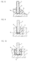
- FIG. 8 it is shown that with appropriate viscosity of the potting compound 14, the material measure can also be clamped in without a groove.
- the sealing compound 14 By attaching the sealing compound 14, the measuring standard 2 is held in the right-angled shoulder 16 of the housing 1.
- An elastic adhesive layer 10 is provided on the material measure 2 as described in FIG. 2.
- an adhesive layer 10 is provided as the separating layer.
- a sliding layer as shown in Figure 4 to provide.
- combinations of adhesive layer and sliding layer are particularly advantageous as a separating layer.
- the further exemplary embodiment according to FIG. 9 is a variant of the example according to FIG. 6.
- the material measure 2 is provided with an elastic adhesive layer 10 on its narrow edge on the underside and on an adjoining side surface.
- the material measure 2 is laterally fixed to a side surface of the groove 6 via the adhesive layer 10.
- a sliding layer 15 is provided on the adhesive layer 10 of the narrow edge. Between this sliding layer 15 and the base of the groove 6 there is a small distance into which the sealing compound 14 can flow.
- the separating layer in this area therefore consists of the adhesive layer 10 and the sliding layer 15.
- the small distance (about 0.1 to 0.5 mm) between the sliding layer 15 and the base of the groove 6 ensures that the measuring standard 2 is mounted so that it can move longitudinally relative to the housing 1 only in the measuring direction X.
- FIG. 10 shows that the separating layer according to the invention can also be provided between the casting compound 14 and the surfaces of the housing 1.
- a groove 6 is made in the housing 1.
- the embodiment 2 is fixed with a narrow edge via an adhesive layer 10 to the bottom of the groove 6.
- sliding layers 15 are provided on the remaining surfaces of the groove, which separate the sealing compound 14 from the housing 1.
- the separating layer can also be multi-layer, e.g. be built in three layers.
- a casting compound 14 which hardens relatively firmly and is therefore relatively inelastic.
- the invention can also be used with angle measuring devices.
- the graduation of the material measure is applied to an arc.
- the invention can not only be used for material measures made of glass.
- the material measure can also consist of metal or plastic.
- the invention is also not restricted to the photoelectric scanning principle.
- the material measure can also have a division based on the capacitive, inductive or magnetic Principle is based. Several graduation tracks or an absolute information track can also be applied to the material measure.
- the carrier body for the measuring standard 2 does not necessarily have to be a housing, it can also be just a metal rail, as is known in so-called open systems.
- the width of the groove 6 is approximately 6 mm
- the thickness of the material measure 2 is approximately 3 mm
- the thickness of the adhesive layer 10 and the sliding layers 15 is approximately 0.1 mm, so that about 3 mm for the gap for the sealing compound 14 remain.
- the width of the gap with the casting compound 14 is therefore a multiple of the thickness of the adhesive layer 10 and of the sliding layer 15.
Landscapes
- Physics & Mathematics (AREA)
- General Physics & Mathematics (AREA)
- Length Measuring Devices With Unspecified Measuring Means (AREA)
- Body Structure For Vehicles (AREA)
- Vehicle Body Suspensions (AREA)
- Transmission And Conversion Of Sensor Element Output (AREA)
- Analysing Materials By The Use Of Radiation (AREA)
- Devices For Conveying Motion By Means Of Endless Flexible Members (AREA)
Applications Claiming Priority (2)
| Application Number | Priority Date | Filing Date | Title |
|---|---|---|---|
| DE4406797A DE4406797C2 (de) | 1994-03-02 | 1994-03-02 | Positionsmeßeinrichtung |
| DE4406797 | 1994-03-02 |
Publications (3)
| Publication Number | Publication Date |
|---|---|
| EP0671606A2 true EP0671606A2 (fr) | 1995-09-13 |
| EP0671606A3 EP0671606A3 (fr) | 1997-01-15 |
| EP0671606B1 EP0671606B1 (fr) | 1999-03-17 |
Family
ID=6511604
Family Applications (1)
| Application Number | Title | Priority Date | Filing Date |
|---|---|---|---|
| EP94119566A Expired - Lifetime EP0671606B1 (fr) | 1994-03-02 | 1994-12-10 | Dispositif de mesure de positions |
Country Status (5)
| Country | Link |
|---|---|
| US (1) | US5611148A (fr) |
| EP (1) | EP0671606B1 (fr) |
| JP (1) | JP2929572B2 (fr) |
| AT (1) | ATE177834T1 (fr) |
| DE (2) | DE4406797C2 (fr) |
Families Citing this family (19)
| Publication number | Priority date | Publication date | Assignee | Title |
|---|---|---|---|---|
| DE19543647C2 (de) * | 1995-11-23 | 2000-05-04 | Heidenhain Gmbh Dr Johannes | Längenmeßeinrichtung zur Messung der Relativlage zweier Objekte |
| EP0836078B1 (fr) * | 1996-10-11 | 2002-12-18 | Dr. Johannes Heidenhain GmbH | Echelle de mesure ainsi que procédé de montage pour un appareil de mesure de longueur |
| JP4174096B2 (ja) * | 1998-03-31 | 2008-10-29 | ソニーマニュファクチュアリングシステムズ株式会社 | 位置検出装置 |
| DE19912310B4 (de) * | 1999-03-19 | 2007-11-29 | Dr. Johannes Heidenhain Gmbh | Positionsmeßeinrichtung |
| DE19918654B4 (de) | 1999-04-16 | 2004-07-15 | Dr. Johannes Heidenhain Gmbh | Sicherungsvorrichtung für den Transport und die Montage einer Meßeinrichtung |
| DE19922363A1 (de) * | 1999-05-14 | 2000-11-23 | Rexroth Star Gmbh | Einrichtung zur Ermittlung der Relativposition zweier relativ zueinander beweglicher Körper und Verfahren zur Herstellung einer solchen Einrichtung |
| DE19941587B4 (de) * | 1999-09-01 | 2010-06-02 | Schaeffler Kg | Linearlager mit einer Einrichtung zum Messen |
| US6820348B2 (en) * | 2001-02-09 | 2004-11-23 | Acu-Rite, Inc. | Mounting tool for linear encoders |
| JP4024600B2 (ja) * | 2002-06-25 | 2007-12-19 | 株式会社ミツトヨ | 枠多点固定タイプのユニット型直線変位測定装置、及び、その固定方法 |
| US6910279B1 (en) | 2004-05-12 | 2005-06-28 | Dr. Johannes Heidenhain Gmbh | Holder for a graduated element |
| EP1621847B1 (fr) * | 2004-07-23 | 2013-07-17 | Dr. Johannes Heidenhain GmbH | Elément, en particulier capteur, et procédé pour coller ledit élément |
| US7299562B2 (en) * | 2005-09-22 | 2007-11-27 | Acu-Rite Companies, Inc. | Device and method for mounting a position measuring device onto a machine tool, and position measuring system |
| DE102005055513B4 (de) * | 2005-11-18 | 2021-05-06 | Dr. Johannes Heidenhain Gmbh | Vorrichtung mit einem Trägerkörper und einem Maßstab |
| US20100162582A1 (en) * | 2008-12-30 | 2010-07-01 | Chih-Mao Shiao | Positioning Device of a Magnetic Ruler |
| JP2014224705A (ja) | 2013-05-15 | 2014-12-04 | キヤノン株式会社 | スケール保持装置、およびエンコーダ |
| DE102014119396A1 (de) * | 2014-12-22 | 2016-06-23 | Endress + Hauser Gmbh + Co. Kg | Druckmesseinrichtung |
| EP3076218A1 (fr) | 2015-03-31 | 2016-10-05 | Canon Kabushiki Kaisha | Appareil à platine et microscope |
| DE102018130985B3 (de) * | 2018-10-02 | 2020-03-05 | Schaeffler Technologies AG & Co. KG | Profilschiene und Verfahren zur Herstellung einer Profilschiene für eine Linearführung |
| DE102022121460A1 (de) * | 2022-08-25 | 2024-03-07 | TRUMPF Werkzeugmaschinen SE + Co. KG | Maßverkörperungseinheit für eine induktive Längenmesseinrichtung einer Werkzeugmaschine, Verfahren und Werkzeug zum Herstellen der Maßverkörperungseinheit sowie Längenmesseinrichtung und Werkzeugmaschine |
Family Cites Families (15)
| Publication number | Priority date | Publication date | Assignee | Title |
|---|---|---|---|---|
| DE2505587C3 (de) * | 1975-02-11 | 1980-10-09 | Dr. Johannes Heidenhain Gmbh, 8225 Traunreut | Längenmeßeinrichtung |
| DE2505585C3 (de) * | 1975-02-11 | 1978-06-08 | Dr. Johannes Heidenhain Gmbh, 8225 Traunreut | Längenmeßeinrichtung |
| DE2643304B2 (de) * | 1976-09-25 | 1980-01-31 | Fagor Electrotecnica, Sdad.Coop., Mondragon, Guipuzcoa (Spanien) | Photoelektrische Einrichtung zum Messen der relativen Lage von Gegenständen |
| JPS5726004U (fr) * | 1980-07-21 | 1982-02-10 | ||
| JPS58174806A (ja) * | 1982-04-07 | 1983-10-13 | Mitsutoyo Mfg Co Ltd | 直線型変位測定機 |
| EP0118607B1 (fr) * | 1983-02-12 | 1989-02-01 | Dr. Johannes Heidenhain GmbH | Dispositif de mesure capsulé |
| US4569137A (en) * | 1983-06-07 | 1986-02-11 | Mitutoyo Mfg. Co., Ltd. | Linear scale type displacement measuring device and main scale attaching method thereof |
| JPS61219818A (ja) * | 1985-03-27 | 1986-09-30 | Nippon Kogaku Kk <Nikon> | 測長装置 |
| DE3605789C1 (de) * | 1986-02-22 | 1987-04-16 | Heidenhain Gmbh Dr Johannes | Lichtelektrische inkrementale Positionsmesseinrichtung |
| US4815213A (en) * | 1987-10-09 | 1989-03-28 | Brown & Sharpe Manufacturing Co. | Apparatus for temperature compensation of sensing means of a machine |
| DE3929629A1 (de) * | 1989-09-06 | 1991-03-07 | Zeiss Carl Fa | Laengen- oder winkelmesseinrichtung |
| DE4021919C2 (de) * | 1990-07-10 | 1995-06-08 | Heidenhain Gmbh Dr Johannes | Maßverkörperung |
| AT394446B (de) * | 1990-10-11 | 1992-03-25 | Rsf Elektronik Gmbh | Inkrementales laengenmesssystem |
| EP0506649B1 (fr) * | 1991-03-25 | 1995-04-19 | RSF-Elektronik Gesellschaft m.b.H. | Dispositif de mesure de longueurs |
| ATE108271T1 (de) * | 1991-05-11 | 1994-07-15 | Heidenhain Gmbh Dr Johannes | Positionsmesseinrichtung. |
-
1994
- 1994-03-02 DE DE4406797A patent/DE4406797C2/de not_active Expired - Fee Related
- 1994-12-10 EP EP94119566A patent/EP0671606B1/fr not_active Expired - Lifetime
- 1994-12-10 DE DE59407967T patent/DE59407967D1/de not_active Expired - Lifetime
- 1994-12-10 AT AT94119566T patent/ATE177834T1/de not_active IP Right Cessation
-
1995
- 1995-02-24 JP JP7037329A patent/JP2929572B2/ja not_active Expired - Fee Related
- 1995-03-02 US US08/396,830 patent/US5611148A/en not_active Expired - Fee Related
Also Published As
| Publication number | Publication date |
|---|---|
| JPH07324925A (ja) | 1995-12-12 |
| EP0671606A3 (fr) | 1997-01-15 |
| DE59407967D1 (de) | 1999-04-22 |
| JP2929572B2 (ja) | 1999-08-03 |
| US5611148A (en) | 1997-03-18 |
| ATE177834T1 (de) | 1999-04-15 |
| EP0671606B1 (fr) | 1999-03-17 |
| DE4406797A1 (de) | 1995-09-07 |
| DE4406797C2 (de) | 1997-11-27 |
Similar Documents
| Publication | Publication Date | Title |
|---|---|---|
| EP0671606B1 (fr) | Dispositif de mesure de positions | |
| DE2853771C2 (de) | Längenmeßeinrichtung | |
| DE19912310B4 (de) | Positionsmeßeinrichtung | |
| EP0671608B1 (fr) | Dispositif de mesure de positions | |
| EP2549240B1 (fr) | Dispositif de mesure de longueur | |
| EP0513406B1 (fr) | Dispositif de mesure de position | |
| EP2018511B1 (fr) | Machine de mesure ou d'usinage de pièces, notamment appareil de mesure de coordonnées | |
| EP0681159B1 (fr) | Dispositif de mesure de position à compensation de température | |
| EP0158050B1 (fr) | Dispositif de mesure capsulé | |
| DE4021190C1 (fr) | ||
| DE4406798C2 (de) | Positionsmeßeinrichtung | |
| DE10308404A1 (de) | Gekapseltes Längenmesssystem | |
| EP0143410A2 (fr) | Dispositif de déplacement linéaire | |
| DE4021919C2 (de) | Maßverkörperung | |
| DE3208591A1 (de) | Laengen- oder winkelmesssystem | |
| EP0506649A2 (fr) | Dispositif de mesure de longueurs | |
| DE3434993A1 (de) | Schieblehre | |
| DE60308136T2 (de) | Massstab-Vorrichtung | |
| DE9422021U1 (de) | Positionsmeßeinrichtung | |
| EP0479766A2 (fr) | Système de mesure de longueurs | |
| DE29521985U1 (de) | Positionsmeßeinrichtung | |
| DE102016204729B4 (de) | Permanentmagnetischer Maßstab | |
| DE9422020U1 (de) | Positionsmeßeinrichtung | |
| EP0364776A2 (fr) | Appareil de dessin | |
| EP0418212A2 (fr) | Boîtier de protection pour prise de règle et unité de palpage à déplacement longitudinal |
Legal Events
| Date | Code | Title | Description |
|---|---|---|---|
| PUAI | Public reference made under article 153(3) epc to a published international application that has entered the european phase |
Free format text: ORIGINAL CODE: 0009012 |
|
| AK | Designated contracting states |
Kind code of ref document: A2 Designated state(s): AT CH DE FR GB IT LI |
|
| PUAL | Search report despatched |
Free format text: ORIGINAL CODE: 0009013 |
|
| AK | Designated contracting states |
Kind code of ref document: A3 Designated state(s): AT CH DE FR GB IT LI |
|
| 17P | Request for examination filed |
Effective date: 19961206 |
|
| 17Q | First examination report despatched |
Effective date: 19970627 |
|
| GRAG | Despatch of communication of intention to grant |
Free format text: ORIGINAL CODE: EPIDOS AGRA |
|
| GRAG | Despatch of communication of intention to grant |
Free format text: ORIGINAL CODE: EPIDOS AGRA |
|
| GRAH | Despatch of communication of intention to grant a patent |
Free format text: ORIGINAL CODE: EPIDOS IGRA |
|
| GRAH | Despatch of communication of intention to grant a patent |
Free format text: ORIGINAL CODE: EPIDOS IGRA |
|
| GRAA | (expected) grant |
Free format text: ORIGINAL CODE: 0009210 |
|
| AK | Designated contracting states |
Kind code of ref document: B1 Designated state(s): AT CH DE FR GB IT LI |
|
| REF | Corresponds to: |
Ref document number: 177834 Country of ref document: AT Date of ref document: 19990415 Kind code of ref document: T |
|
| REG | Reference to a national code |
Ref country code: CH Ref legal event code: NV Representative=s name: TROESCH SCHEIDEGGER WERNER AG Ref country code: CH Ref legal event code: EP |
|
| GBT | Gb: translation of ep patent filed (gb section 77(6)(a)/1977) |
Effective date: 19990319 |
|
| ET | Fr: translation filed | ||
| REF | Corresponds to: |
Ref document number: 59407967 Country of ref document: DE Date of ref document: 19990422 |
|
| PLBE | No opposition filed within time limit |
Free format text: ORIGINAL CODE: 0009261 |
|
| STAA | Information on the status of an ep patent application or granted ep patent |
Free format text: STATUS: NO OPPOSITION FILED WITHIN TIME LIMIT |
|
| 26N | No opposition filed | ||
| REG | Reference to a national code |
Ref country code: GB Ref legal event code: IF02 |
|
| PGFP | Annual fee paid to national office [announced via postgrant information from national office to epo] |
Ref country code: AT Payment date: 20051220 Year of fee payment: 12 |
|
| PG25 | Lapsed in a contracting state [announced via postgrant information from national office to epo] |
Ref country code: AT Free format text: LAPSE BECAUSE OF NON-PAYMENT OF DUE FEES Effective date: 20061210 |
|
| PGFP | Annual fee paid to national office [announced via postgrant information from national office to epo] |
Ref country code: FR Payment date: 20061212 Year of fee payment: 13 |
|
| REG | Reference to a national code |
Ref country code: FR Ref legal event code: ST Effective date: 20081020 |
|
| PG25 | Lapsed in a contracting state [announced via postgrant information from national office to epo] |
Ref country code: FR Free format text: LAPSE BECAUSE OF NON-PAYMENT OF DUE FEES Effective date: 20071231 |
|
| PGFP | Annual fee paid to national office [announced via postgrant information from national office to epo] |
Ref country code: IT Payment date: 20091218 Year of fee payment: 16 |
|
| PGFP | Annual fee paid to national office [announced via postgrant information from national office to epo] |
Ref country code: CH Payment date: 20101224 Year of fee payment: 17 |
|
| PGFP | Annual fee paid to national office [announced via postgrant information from national office to epo] |
Ref country code: GB Payment date: 20101221 Year of fee payment: 17 |
|
| PG25 | Lapsed in a contracting state [announced via postgrant information from national office to epo] |
Ref country code: IT Free format text: LAPSE BECAUSE OF NON-PAYMENT OF DUE FEES Effective date: 20101210 |
|
| PGFP | Annual fee paid to national office [announced via postgrant information from national office to epo] |
Ref country code: DE Payment date: 20111222 Year of fee payment: 18 |
|
| REG | Reference to a national code |
Ref country code: CH Ref legal event code: PL |
|
| GBPC | Gb: european patent ceased through non-payment of renewal fee |
Effective date: 20111210 |
|
| PG25 | Lapsed in a contracting state [announced via postgrant information from national office to epo] |
Ref country code: GB Free format text: LAPSE BECAUSE OF NON-PAYMENT OF DUE FEES Effective date: 20111210 Ref country code: LI Free format text: LAPSE BECAUSE OF NON-PAYMENT OF DUE FEES Effective date: 20111231 Ref country code: CH Free format text: LAPSE BECAUSE OF NON-PAYMENT OF DUE FEES Effective date: 20111231 |
|
| PG25 | Lapsed in a contracting state [announced via postgrant information from national office to epo] |
Ref country code: DE Free format text: LAPSE BECAUSE OF NON-PAYMENT OF DUE FEES Effective date: 20130702 |
|
| REG | Reference to a national code |
Ref country code: DE Ref legal event code: R119 Ref document number: 59407967 Country of ref document: DE Effective date: 20130702 |