EP0671708A2 - Münzprüfer - Google Patents
Münzprüfer Download PDFInfo
- Publication number
- EP0671708A2 EP0671708A2 EP19940110440 EP94110440A EP0671708A2 EP 0671708 A2 EP0671708 A2 EP 0671708A2 EP 19940110440 EP19940110440 EP 19940110440 EP 94110440 A EP94110440 A EP 94110440A EP 0671708 A2 EP0671708 A2 EP 0671708A2
- Authority
- EP
- European Patent Office
- Prior art keywords
- coins
- coin
- chute
- slits
- genuine
- Prior art date
- Legal status (The legal status is an assumption and is not a legal conclusion. Google has not performed a legal analysis and makes no representation as to the accuracy of the status listed.)
- Withdrawn
Links
Images



Classifications
-
- G—PHYSICS
- G07—CHECKING-DEVICES
- G07D—HANDLING OF COINS OR VALUABLE PAPERS, e.g. TESTING, SORTING BY DENOMINATIONS, COUNTING, DISPENSING, CHANGING OR DEPOSITING
- G07D5/00—Testing specially adapted to determine the identity or genuineness of coins, e.g. for segregating coins which are unacceptable or alien to a currency
- G07D5/005—Testing the surface pattern, e.g. relief
Definitions
- This invention relates to an apparatus for checking coins as to whether they are genuine coins of a given denomination or not, with or without the capability of sorting them accordingly, and with or without the capability of counting the coins that have proved to be genuine, as well as those which have proved otherwise.
- the apparatus according to the invention finds use as a coin checker, banking machine, vending machine or the like.
- Known machines of this general character may be broadly classified into two categories, one being the mechanical type relying on the diameters, weights or like properties of coins, and the other being the electronic type relying on the magnetic, optical or like characteristics of coins. Both types are alike, however, in that the coins are checked while they are sliding, rolling or falling along a predefined passageway.
- a problem common to such conventional machines is that the coins are easy to jam in the passageway, particularly if they are stained or dust covered or if the coins or the passageway is wet. Even if the coins do not jam, the stained, dust covered, or moist coins have been very liable to travel at variable speed past the check station on the passageway. Such changes in traveling speed have often resulted in errors in coin identification.
- the present invention seeks to check coins more accurately than heretofore even if the coins are fed at variable speed because of stains or dust accumulations thereon or by moisture.
- the invention also seeks to feed coins one by one more positively than heretofore along a predetermined path even if they are supplied in a batch and if they are stained or dust covered or wet.
- the invention may be summarized as an apparatus for checking coins as to whether they are genuine coins of a preselected denomination or not.
- a coin chute having a plurality of slits formed in a prescribed pattern at a check station intermediate an entrance end and an exit end thereof.
- a dark box is disposed on one side of the chute for providing an optically dark space which is open to the slits in the chute and which has an optical coin sensor disposed therein.
- a camera means Disposed on another side of the chute is a camera means for imaging each coin traveling over the slits in the chute.
- a control means is electrically connected to the coin sensor and the camera means for causing the latter to image each coin in response to a signal from the coin sensor and for judging, in response to an image signal from the camera means, whether each coin is a genuine coin of a preselected denomination or not.
- the coin sensor Positioned in the dark space, the coin sensor can accurately detect the arrival of each coin at the check station as the coin, traveling down the chute, covers the slits open to the dark space. This method of coin detection is totally unaffected by stains or dust accumulations on the coin.
- the control means on inputting the coin arrival signal from the coin sensor causes the camera means to image the coin at the check station. The image signal from the camera means is sent back to the control means, which then determines whether the coin is genuine or not by the known pattern matching method.
- coins are forcibly fed along the chute by transport means.
- the transport means comprises a belt conveyor for transporting the coins from the entrance end to the check station, and another such conveyor for transporting the coins, after having been checked, from the check station to the exit end.
- Each conveyor has an endless belt capable of frictional engagement with the coins, so that the coins are forcibly transported one by one down the chute in sliding contact therewith, against the possibility of jamming on the chute.
- the coins may be transported at a lower speed by the upstream conveyor than by the downstream conveyor. In this manner there will be no likelihood of two or more coins collecting at the check station, awaiting discharge by the downstream conveyor.
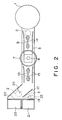
- FIGS. 1 and 2 schematically illustrate only those parts of the coin checker which are essential for the understanding of the invention, and FIG. 3 shows a typical external appearance of the complete coin checker.
- the coin checker includes a hopper 1 into which coins to be checked are charged. Centrifugally flung away one by one from the hopper 1, the coins 2 are to be loaded on a sloping chute 3 at its entrance end, shown directed to the right in FIGS. 1 and 2 , and to travel therealong to its exit end past a check station intermediate the entrance and the exit ends.
- the chute 3 has formed therein a plurality of slits indicated at 4 in FIG. 1 and shown more clearly in FIG. 4 in plan view and on an enlarged scale. It will be seen that four slits 4 a -4 d of the same shape and size are provided radially at constant angular spacings. More specifically, the slits 4 a and 4 b are aligned longitudinally of the chute 3, and the other two slits 4 c and 4 d transversely of the chute.
- a dark box 5 is mounted to the underside or back side of the chute 3, that is, the side opposite to the one on which the coins 2 travel.
- the dark box provides an optically dark space to which the slits 4 are open directly.
- a coin sensor 6 in the form of a photodetector or photosensor is disposed within the dark box 5, in a position of registry with the slit 4 b , for optically sensing each coin traveling over the slits 4 in a manner yet to be described.
- coin imaging means comprising a stroboscope 7 of annular shape and an electronic imaging device 8 such as a charge coupled camera.
- the stroboscope 7 and camera 8 are arranged coaxially with each other, normal to the plane of the chute 3, and concentrically with the radial arrangement of the four slits 4.
- the imaging means 7 and 8 image each coin traveling over the slits 4, when that coin is sensed by the coin sensor 6, and provides an electric coin image signal representative of the coin.
- FIGS. 1 and 2 further reveal an upstream conveyor 9 for forcibly transporting the successive coins along the chute 3 from the entrance end to the check station, and a downstream conveyor 10 for forcibly transporting the coins along the chute from the check station to the exit end.
- Both conveyors 9 and 10 are shown as belt conveyors, each comprising a pair of pulleys and an endless belt running thereon. The endless belts are capable of frictional engagement with the coins, transporting them in sliding contact with the chute. It is understood that both belt conveyors 9 and 10 are driven by separate electric motors, not shown.
- speed sensors which can also be photodetectors, for sensing the peripheral speeds of the drive pulleys of the belt conveyors 9 and 10.
- Drive pulley speed signals from these speed sensors 11 and 12, as well as a coin image signal from the camera 8, are sent to control electronics 13.
- the control 13 controls the unshown drive means of the belt conveyors so that the downstream conveyor 10 transports the coins at higher speed than does the upstream conveyor 9. No problem will normally occur, however, if both belt conveyors run at the same speed.
- a pair of coin guides 14 with flaring upstream ends may be provided on the chute 3 on both sides of the upstream conveyor 9, and another similar pair of coin guides 15 on both sides of the downstream conveyor 10.
- such sorting means Adjacent the exit end of the chute 3 there are provided means for sorting the coins and directing them to two different paths according to whether they are good or band, that is, whether they are genuine coins of some particular denomination or not.
- sorting means include a deflector 17 pivotable between a retracted position, in which it lies under the chute 3, and a working position in which it projects into the chute. Normally held retracted under the bias of a helical extension spring 18 as shown in FIG. 1 , the deflector 17 pivots against the force of the spring when a deflector actuator, herein shown as a solenoid 16, is energized in response to a signal from the control 13.
- the exit end of the chute 3 communicates with a good coin discharge port 19 and a bad coin discharge port 20.
- the good coin discharge port 19 is open to an optional good coin recovery box 21, and the bad coin discharge port 20 to an optional bad coin recovery box 22.
- the deflector 17 When a coin at the check station is judged to be good by the control 13, the deflector 17 will be held retracted, allowing that coin to travel straight from the downstream belt conveyor 10 and fall into the good coin recovery box 22. If the coin proves to be bad, on the other hand, then the solenoid 16 will be energized thereby pivoting the deflector 17 to the working position. The deflector 17 in its working position will deflect the bad coin away from the straight path and direct it toward the bad coin discharge port 20, from which the coin will fall into the bad coin recovery box 22.
- two additional optical coin sensors may be provided adjacent the good coin discharge port 19 and bad coin discharge port 20, respectively.
- the good coin sensor 23 and bad coin sensor 24 may both be connected to the control 13 in order to enable the same to know that the coins are being sorted correctly. Due to some machine trouble or other, troubles being almost unavoidable in this and any kinds of machines, a coin that has been judged to be good may be sensed by the bad coin sensor 24, and a coin that has been judged to be bad by the genuine coin sensor 23. In such cases either the complete machine may be set out of operation, or an alarm may be triggered off, and the incorrectly sorted coins may be rechecked as required.
- the coin checker has a control panel 25 having various control and display means arranged thereon.
- this machine can be set in either check mode or teach mode.
- the machine checks coins when set in check mode.
- the machine needs reference data on the head and tail patterns of the coins of each denomination to be checked.
- the teach mode is therefore first selected to teach the machine the reference data. It relies on the reference data to determine whether each coin is a proper coin of the specified denomination or not in the subsequent check mode of operation.
- control panel 25 includes a "Coin Count” screen 26 which displays in real time during check mode of operation both the number of coins that have proved good and the number of coins that have proved otherwise.
- the screen 26 consists of two sections, with the top section indicating the number of good coins and the bottom section indicating the number of bad coins.
- the "OK" and “NG” signs 27 will be lit up to denote what the counts mean.
- the "Coin Count” screen 26 indicates the number of sample coins whose head pattern has been taught, and the number of those whose tail pattern has been taught.
- a reset pushbutton switch 28 is to be depressed by the operator for resetting the counts only in check mode.
- a “Teaching” section 29 includes several light emitting diodes (LEDs). These LEDs are to glow individually to indicate the progress of teaching during teach mode of operation.
- LEDs light emitting diodes
- a "Mode Select" switch 30 is to be actuated by the operator for setting the machine in either check mode or teach mode.
- the control panel 25 further includes a set of "Pattern Select" pushbutton switches 31 to be selectively depressed to indicate the particular denomination of coins to be checked or to teach. Any depressed switch will blink, indicating that some particular denomination of coins has been chosen for checking or teaching. Any constantly glowing switch or switches indicate that the corresponding denomination or denominations of coins have been taught and, therefore, that the switch or switches may be depressed for immediate commencement of check mode. Any unlit switch or switches indicate that the machine has not learned about the corresponding denomination or denominations of coins and, therefore, that the machine must first be set in teach mode by the "Mode Select" switch 30.
- a suitable number of good coins of the desired denomination may be introduced into the hopper 1, FIGS. 1-3 . according to step S2 .
- the control 13 will automatically collect the required reference data at step S3 .
- the "Mode Select" switch 30 may be set in check mode.
- a batch of coins of the presumably desired denomination may now be charged into the hopper 1, as indicated at step S4 .
- Centrifugally driven away from the hopper the cons will travel one by one down the chute 3 as the upstream conveyor 9, FIGS. 1 and 2 , forcibly transports them in sliding contact with the chute, as at steps S5 and S6 .
- the speed of the upstream conveyor 9 is such that each coin on being frictionally engaged by the conveyor belt will be accelerated down the chute, with the consequent creation of a conveniently large space from one coin to the next.
- step S7 the sensing of the arrival of each coin at the check station by the coin sensor 6, FIGS. 1 and 4 .
- the coin sensor 6 will signal the control 13 when a coin comes over the slits 4 in the chute 3 whereupon the control will cause the stroboscope 7 to flash, as at step S8 , and the camera 8 to shoot the coin, as at step S9 .
- the camera 8 will then send an image signal, representative of the image of the coin, to the control 13, which will then process the image signal for subsequent pattern matching, as at S10 .
- the control 13 compares the head or tail pattern of the coin with the reference head and tail patterns that have been taught previously. If the coin is good, its pattern will agree with either reference pattern. A 100 percent agreement is not a necessity, however. Coins of the same denomination may not necessarily be exactly alike, but slight differences may exist according to the years of their mintage. Such coins can nevertheless be judged to be good or bad according to whether their likeness to the reference patterns comes up to, or falls short of, a critical percentage that may be predetermined statistically.
- the coin will be accelerated down the chute 3 by the downstream conveyor 10 and fall from the good coin discharge port 19 into the good coin recovery box 21, according to steps S12 and S13 .
- the control 13 will cause the solenoid 16 to be energized, as at step S14 , and hence to pivot the deflector 17 to its working position against the force of the tension spring 18, FIG. 1 . Then the bad coin will be accelerated down the chute 3 by the downstream conveyor 10 and, after hitting the deflector 17, fall from the bad coin discharge port 20 into the bad coin recovery box 22, according to steps S12 and S15 .
- the running speed of the downstream conveyor 10 be higher than that of the upstream conveyor 9. This difference admits of some variable delay in the traveling speed of the coins past the check station. The coins will not jam at the check station as they are moved away therefrom at a higher speed by the downstream conveyor 10 than the upstream conveyor 9 brings the coins to the check station.
Landscapes
- Physics & Mathematics (AREA)
- General Physics & Mathematics (AREA)
- Testing Of Coins (AREA)
- Sorting Of Articles (AREA)
Applications Claiming Priority (2)
| Application Number | Priority Date | Filing Date | Title |
|---|---|---|---|
| JP6040008A JPH07249143A (ja) | 1994-03-10 | 1994-03-10 | コイン選別装置 |
| JP40008/94 | 1994-03-10 |
Publications (1)
| Publication Number | Publication Date |
|---|---|
| EP0671708A2 true EP0671708A2 (de) | 1995-09-13 |
Family
ID=12568886
Family Applications (1)
| Application Number | Title | Priority Date | Filing Date |
|---|---|---|---|
| EP19940110440 Withdrawn EP0671708A2 (de) | 1994-03-10 | 1994-07-05 | Münzprüfer |
Country Status (2)
| Country | Link |
|---|---|
| EP (1) | EP0671708A2 (de) |
| JP (1) | JPH07249143A (de) |
Cited By (5)
| Publication number | Priority date | Publication date | Assignee | Title |
|---|---|---|---|---|
| CN102663849A (zh) * | 2012-05-09 | 2012-09-12 | 苏州爱锐邦智能科技有限公司 | 具有外观防伪功能的硬币投币器 |
| CN103364411A (zh) * | 2013-07-18 | 2013-10-23 | 江苏科思机电工程有限公司 | 一种工件表面和边缘质量检测机及其检测方法 |
| CN105225331A (zh) * | 2015-10-28 | 2016-01-06 | 威海华菱光电股份有限公司 | 硬币检测设备和硬币检测方法 |
| CN106652160A (zh) * | 2016-10-26 | 2017-05-10 | 南京中钞长城金融设备有限公司 | 一种色差检验装置 |
| WO2018219186A1 (zh) * | 2017-05-27 | 2018-12-06 | 山东新北洋信息技术股份有限公司 | 硬币分离装置及分离方法 |
Families Citing this family (2)
| Publication number | Priority date | Publication date | Assignee | Title |
|---|---|---|---|---|
| EP3784419B1 (de) * | 2018-04-26 | 2026-04-15 | Sortera Technologies, Inc. | Wiederverwertung von münzen aus schrott |
| KR102237542B1 (ko) * | 2019-11-13 | 2021-04-07 | (주)인터패스 | 카메라를 이용한 동전인식 계수기 |
-
1994
- 1994-03-10 JP JP6040008A patent/JPH07249143A/ja active Pending
- 1994-07-05 EP EP19940110440 patent/EP0671708A2/de not_active Withdrawn
Cited By (6)
| Publication number | Priority date | Publication date | Assignee | Title |
|---|---|---|---|---|
| CN102663849A (zh) * | 2012-05-09 | 2012-09-12 | 苏州爱锐邦智能科技有限公司 | 具有外观防伪功能的硬币投币器 |
| CN103364411A (zh) * | 2013-07-18 | 2013-10-23 | 江苏科思机电工程有限公司 | 一种工件表面和边缘质量检测机及其检测方法 |
| CN103364411B (zh) * | 2013-07-18 | 2016-05-04 | 江苏科思机电工程有限公司 | 一种工件表面和边缘质量检测机及其检测方法 |
| CN105225331A (zh) * | 2015-10-28 | 2016-01-06 | 威海华菱光电股份有限公司 | 硬币检测设备和硬币检测方法 |
| CN106652160A (zh) * | 2016-10-26 | 2017-05-10 | 南京中钞长城金融设备有限公司 | 一种色差检验装置 |
| WO2018219186A1 (zh) * | 2017-05-27 | 2018-12-06 | 山东新北洋信息技术股份有限公司 | 硬币分离装置及分离方法 |
Also Published As
| Publication number | Publication date |
|---|---|
| JPH07249143A (ja) | 1995-09-26 |
Similar Documents
| Publication | Publication Date | Title |
|---|---|---|
| JP5460299B2 (ja) | 硬貨処理機 | |
| EP2188788B1 (de) | Verfahren und sensor zur erfassung von münzen zur wertermittlung | |
| US9070240B2 (en) | Method and apparatus for offsorting coins in a coin handling machine | |
| WO2001015090A1 (en) | Coin counting and sorting device | |
| EP0671708A2 (de) | Münzprüfer | |
| US5755336A (en) | Optical sorter, tracker and reader | |
| KR100780052B1 (ko) | 주화 선별/계수장치 | |
| GB2060970A (en) | Coin sorting device | |
| US8708129B2 (en) | Method and system for dust prevention in a coin handling machine | |
| JPH0844924A (ja) | 卓上型硬貨計数分類機 | |
| JP3405643B2 (ja) | 硬貨選別機 | |
| US4598724A (en) | Coin counter | |
| SE520989C2 (sv) | Tillbehör för en mynthanteringsapparat | |
| JP3266444B2 (ja) | 卓上型硬貨計数分類機 | |
| JP3241578B2 (ja) | 硬貨選別計数装置 | |
| JPH06274734A (ja) | 硬貨処理装置 | |
| JP2766599B2 (ja) | 硬貨選別装置 | |
| JP2634122B2 (ja) | 硬貨選別分類機 | |
| JP2011034141A (ja) | 硬貨入出金装置 | |
| JP3405644B2 (ja) | 硬貨選別機 | |
| EP0665970B1 (de) | Vorrichtung und verfahren zum fördern von münzen | |
| JP5985715B2 (ja) | 硬貨繰出装置、硬貨入出金機および硬貨繰出方法 | |
| JPH1079068A (ja) | カセット装填検知装置 | |
| JPH08212407A (ja) | 硬貨繰出装置 | |
| JPH05298517A (ja) | 硬貨選別分類機 |
Legal Events
| Date | Code | Title | Description |
|---|---|---|---|
| PUAI | Public reference made under article 153(3) epc to a published international application that has entered the european phase |
Free format text: ORIGINAL CODE: 0009012 |
|
| AK | Designated contracting states |
Kind code of ref document: A2 Designated state(s): DE FR GB |
|
| STAA | Information on the status of an ep patent application or granted ep patent |
Free format text: STATUS: THE APPLICATION IS DEEMED TO BE WITHDRAWN |
|
| 18D | Application deemed to be withdrawn |
Effective date: 19970201 |