EP0672367A2 - Ruban tissé pour fermeture à glissière - Google Patents
Ruban tissé pour fermeture à glissière Download PDFInfo
- Publication number
- EP0672367A2 EP0672367A2 EP95107407A EP95107407A EP0672367A2 EP 0672367 A2 EP0672367 A2 EP 0672367A2 EP 95107407 A EP95107407 A EP 95107407A EP 95107407 A EP95107407 A EP 95107407A EP 0672367 A2 EP0672367 A2 EP 0672367A2
- Authority
- EP
- European Patent Office
- Prior art keywords
- stringer
- coupling
- woven
- tape
- warp threads
- Prior art date
- Legal status (The legal status is an assumption and is not a legal conclusion. Google has not performed a legal analysis and makes no representation as to the accuracy of the status listed.)
- Granted
Links
Images


Classifications
-
- D—TEXTILES; PAPER
- D03—WEAVING
- D03D—WOVEN FABRICS; METHODS OF WEAVING; LOOMS
- D03D1/00—Woven fabrics designed to make specified articles
-
- A—HUMAN NECESSITIES
- A44—HABERDASHERY; JEWELLERY
- A44B—BUTTONS, PINS, BUCKLES, SLIDE FASTENERS, OR THE LIKE
- A44B19/00—Slide fasteners
- A44B19/10—Slide fasteners with a one-piece interlocking member on each stringer tape
- A44B19/12—Interlocking member in the shape of a continuous helix
-
- A—HUMAN NECESSITIES
- A44—HABERDASHERY; JEWELLERY
- A44B—BUTTONS, PINS, BUCKLES, SLIDE FASTENERS, OR THE LIKE
- A44B19/00—Slide fasteners
- A44B19/24—Details
- A44B19/34—Stringer tapes; Flaps secured to stringers for covering the interlocking members
- A44B19/346—Woven stringer tapes
-
- A—HUMAN NECESSITIES
- A44—HABERDASHERY; JEWELLERY
- A44B—BUTTONS, PINS, BUCKLES, SLIDE FASTENERS, OR THE LIKE
- A44B19/00—Slide fasteners
- A44B19/24—Details
- A44B19/40—Connection of separate, or one-piece, interlocking members to stringer tapes; Reinforcing such connections, e.g. by stitching
- A44B19/406—Connection of one-piece interlocking members
-
- A—HUMAN NECESSITIES
- A44—HABERDASHERY; JEWELLERY
- A44B—BUTTONS, PINS, BUCKLES, SLIDE FASTENERS, OR THE LIKE
- A44B19/00—Slide fasteners
- A44B19/42—Making by processes not fully provided for in one other class, e.g. B21D53/50, B21F45/18, B22D17/16, B29D5/00
- A44B19/52—Securing the interlocking members to stringer tapes while making the latter
- A44B19/54—Securing the interlocking members to stringer tapes while making the latter while weaving the stringer tapes
-
- D—TEXTILES; PAPER
- D10—INDEXING SCHEME ASSOCIATED WITH SUBLASSES OF SECTION D, RELATING TO TEXTILES
- D10B—INDEXING SCHEME ASSOCIATED WITH SUBLASSES OF SECTION D, RELATING TO TEXTILES
- D10B2501/00—Wearing apparel
- D10B2501/06—Details of garments
- D10B2501/063—Fasteners
- D10B2501/0631—Slide fasteners
-
- Y—GENERAL TAGGING OF NEW TECHNOLOGICAL DEVELOPMENTS; GENERAL TAGGING OF CROSS-SECTIONAL TECHNOLOGIES SPANNING OVER SEVERAL SECTIONS OF THE IPC; TECHNICAL SUBJECTS COVERED BY FORMER USPC CROSS-REFERENCE ART COLLECTIONS [XRACs] AND DIGESTS
- Y10—TECHNICAL SUBJECTS COVERED BY FORMER USPC
- Y10T—TECHNICAL SUBJECTS COVERED BY FORMER US CLASSIFICATION
- Y10T24/00—Buckles, buttons, clasps, etc.
- Y10T24/25—Zipper or required component thereof
- Y10T24/2518—Zipper or required component thereof having coiled or bent continuous wire interlocking surface
- Y10T24/252—Zipper or required component thereof having coiled or bent continuous wire interlocking surface with stringer tape interwoven or knitted therewith
Definitions
- the present invention relates to a woven slide fastener stringer having a row of continous filamentary coupling elements woven integrally into a stringer tape. More particularly, the invention is directed to the provision of a woven slide fastener stringer having such a row of coupling elements which are disposed so as to be concealed or masked from external view when the slide fastener is closed.
- EP-A-0 275 539 which forms the basis of the preamble of claim 1, discloses a woven slide fastener stringer in which a gap-filling warp thread extends under successive loops of a coiled plastic filament and alternately over and under picks of a foundation weft thread.
- US-A-3 961 652 discloses a woven slide fastener stringer in which a row of continous filamentary coupling elements is woven in such a way that the head portion of each of the elements is directed toward the web portion of the stringer tape and the heel portion of the element is oriented to project transversely beyond the longitudinal edge of the tape.
- US-A-3 961 652 fails to teach how to introduce the single weft thread and the element-forming filamentary material into the fell of the stringer tape.
- the present invention seeks to provide a woven slide fastener stringer for a concealed type slide fastener, which stringer has a row of continuous filamentary coupling elements woven to a relatively low profile.
- a woven slide fastener stringer comprising:
- a fixing warp thread system securing said row of coupling elements in position against displacement, characterized in that said fixing warp thread system consists of a plurality of clamping warp threads and a plurality of upper and lower binding warp threads, said upper and lower binding warp threads extending substantially in a straight run over said upper and lower leg portions, respectively, of said coupling elements, and said clamping warp threads extending between two adjacent pairs of upper and lower binding threads over an upper leg portion of one coupling element and under a lower leg portion of an adjacent coupling element and into engagement with said weft thread; said stringer tape being folded back with said coupling head portion of each coupling element projecting transversely beyond said one longitudinal edge of said stringer tape and said weft thread having a straight span formed adjacent said coupling head portion and extending substantially perpendicularly with respect to the general plane of said stringer tape and defining an axis about which said stringer tape is folded back.
- Figures 1 and 2 illustrate an apparatus for manufacturing a woven slide fastener stringer.
- the apparatus comprises a loom 10 for progressively weaving a stringer tape 11 of warp threads 12, 13, 14, 15 at a fell 16, the loom 10 including conventional heddles or a shedding means not shown for forming a pair of upper and lower warp sheds 17, 18 between the warp threads 12, 13, 14, 15 and for selectively moving the warp threads 12 - 15 up and down, a first filling carrier or weft inserter 19 disposed at one longitudinal edge of the warp threads 12 - 15 and reciprocally movable across the upper shed 17 for inserting a weft thread 20 in double picks in the upper warp shed 17 between the warp threads 12 - 15 and a second filling carrier 21 disposed in parallel spaced relation to the first carrier 19 and reciprocally movable for inserting an element-forming filamentary material of synthetic resin 22 in the lower shed 18 between the warp threads 14, 15 woven along one longitudinal edge 11 a of the stringer
- the apparatus includes a reed 23 movable back and forth for beating the weft thread 20 inserted in the shed 17 against the fell 16, and a knitting needle 24 reciprocably disposed at the opposite edge of the warp threads 12 - 15 for successively knitting loops of the weft thread 20 projecting out the warp shed 17 to form a tape selvage.
- the reed 23 has a plurality of longitudinal guide slots 23a through which the warp threads 12, 13 extend to the fell 16.
- the apparatus also includes a coiling means operable in synchronism with the loom 10 for coiling the element-forming filamentary material 22 into a row of coupling elements 25 whereby the row of coupling elements 25 is woven integrally into the stringer tape 11 as the latter is woven.
- the coiling means comprises a rocker arm 26 disposed at the one edge of the warp threads 12 - 15 and rockingly movable about one of its ends. As better shown in Figure 3, the rocker arm 26 has at the opposite or distal end a hook 27 including a head portion 27a and a nose portion 27b extending therefrom in a direction parallel to the warp threads 12 - 15.
- the nose portion 27b has a transverse cross section which defines a space between a pair of upper and lower legs 28, 29 of each coupling element 25.
- the rocker arm 26 has a slanted surface 30 contiguous to the head portion 27a to enable the filamentary material 22 to slide smoothly thereon and over the nose portion 27b when the filamentary material 22 is brought by the second carrier 21 into hooked engagement with the hook 27 in a manner hereafter to be described.
- the hook 27 moves, in a plane substantially perpendicular to the general plane of the stringer tape 11, between a first position shown in Figures 2 and 3 in which it is located in alignment with the fell 16 and a second position shown in Figure 1 in which it is located remotely from the fell 16.
- the coiling means also includes an element-shaping plate 31 removably secured to and movable with the reed 23 toward and away from the fell 16.
- the element-shaping plate 31 has a straight longitudinal punch edge 31a extending in parallel alignment with the slots 23a of the reed 23 and in between the group of warp threads 14 and 15 and adapted to beat the filamentary material 22 against the fell 16, as shown in Figures 2 and 3 and recessed as at 31 to preclude the danger of interference with the rocker arm 26.
- the element-shaping plate 31 may be adjusted, by suitable means such as bolts and nuts, in position relative to the reed 23, or may be replaced as and when it becomes worn on repeated frictional contact with the resinous filamentary material 22.
- the second carrier 21 has a bifurcated end portion 21a a for receiving therein the element-forming filamentary material 22 having the equidistantly spaced prospective coupling head portions 25a (better shown in Figures 4 and 5).
- the second carrier 21 is actuated in timed relation to the rocker arm 26 so that while the hook 27 is at its second position shown in Figure 1, the bifurcated end portion 21 a of the carrier 21 engages the element-forming filamentary material 22 and carries the same over the slanted surface 30 and the hook's head portion 27a into engagement with the nose portion 27b.
- the apparatus thus constructed operates with a cycle of operation which for purpose of illustration begins under the conditions shown in Figure 1 in which the element-forming filamentary material 22 is displaced by the second carrier 21 beyond the warp threads 14, 15 into hooked engagement with the hook 27; the weft thread 20 inserted or laid in by the first carrier 19 through the upper warp shed 17 is ready for hooked engagement with the knitting needle 24; and the reed 23 is retracted in a position away from the fell 16 of the stringer tape 11 being woven. Then, the rocker arm 26 is actuated to move angularly toward the fell 16 whereupon the hook 27 moves from the second position of Figure 1 to the first position of Figures 2 and 3.
- the reed 23 is actuated to move forward to beat the weft thread 20 just inserted against the fell 16 and the element-shaping plate 31 likewise moves forward in between the warp threads 14, 15 to beat the filamentary material 22 against the fell 16 along the longitudinal edge 11 a of the tape 11.
- the element-forming filamentary material 22 is coiled around the hook's nose portion 27b substantially in parallel relation to the fell 16 to thereby form a coupling element 25.
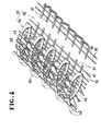
- FIGS 4 - 7 show an example of woven slide fastener stringer 33 produced by the apparatus of the present invention.
- the slide fastener stringer 33 comprises a row of coiled coupling elements 34 formed of synthetic resin fixed to a slide fastener stringer tape 35 woven of foundation warp threads 36 and a single foundation weft thread 37, the row of coupling elements 34 extending along a longitudinal edge portion 38 of the stringer tape 35.
- the foundation warp threads 36 and the foundation weft thread 37 jointly constitute a web portion 39 of the stringer tape 35.
- the row of coupling elements 34 is secured to one longitudinal edge portion 38 of the stringer tape 35 by means of a fixing warp thread system including a plurality of clamping warp threads 40a, 41a, 42a, 40b, 41 b, 42b and a plurality of upper and lower binding warp threads 43a, 44a, 45a, 43b, 44b, 45b.
- Each of the coupling elements 34 comprises a coupling head 47 and a pair of upper and lower legs 48, 49 extending from the coupling head 47 in a common direction and spaced from each other vertically in a direction substantially perpendicular to the general plane of the stringer tape 35.
- the upper and lower legs 48, 49 are merged into and interconnected by a heel portion 50 located remotely from the coupling head 47.
- the heel portion 50 is oriented to project transversely beyond the longitudinal edge portion 38 of the tape 35, while the coupling head 47 is directed toward the web portion 39 of the tape 35.
- the upper and lower binding warp threads 43a - 45a and 43b - 45b extend substantially in a straight run over the upper and lower legs 48 and 49, respectively of the coupling elements 34 so as to provide enhanced positional stability of the elements 34 in the longitudinal direction of the stringer 33.
- the binding warp threads 43a - 45a and 43b - 45b intersect the weft thread 37 in between adjacent coupling elements 34 as shown in Figure 4.
- the clamping warp threads 40a, 41a, 42a, 40b, 41 b, 42b are adapted to bring both legs 48, 49 of the elements 34 closely together.
- the foundation weft thread 37 passes around the last upper warp binding thread 45a up toward and around the last lower warp binding thread 45b to form a straight run or span 51 therebetween adjacent the coupling head 47 of the element 34 which extends substantially perpendicularly with respect to the general plane of the stringer tape 35.
- the straight span 51 of the weft thread 37 defines an axis about which the stringer tape 35 is folded back so that the coupling head portion 47 of each coupling element 34 now projects transversely beyond the longitudinal edge portion 38 of the tape 35, while the heel portion 50 of the element 34 is concealed from view by the web portion 39 of the tape 35 which has been turned over to overlie the heel portion 50 as shown in Figures 6 and 7.
- the abutment 52 on one of a pair of stringers 33 is brought into abutting engagement with that on the other of the paired stringers 33 when the two stringers 33 are coupled together in a well known manner by a slider not shown.
- the abutments 52 thus effectively conceal the row of coupling elements 34 from view and can remain joined together against lateral pull or vertical thrust by the fixing warp thread system described herein which holds the coupling elements 34 firmly in place with the upper and lower legs 48, 49 of the respective elements 34 substantially superimposed one upon another to lie substantially perpendicular to the general plane of the stringer 33 and flattened to assume a relatively low profile as shown in Figures 5-7.
Landscapes
- Engineering & Computer Science (AREA)
- Textile Engineering (AREA)
- Slide Fasteners (AREA)
- Looms (AREA)
- Woven Fabrics (AREA)
- Making Paper Articles (AREA)
- Treatment Of Fiber Materials (AREA)
Applications Claiming Priority (7)
| Application Number | Priority Date | Filing Date | Title |
|---|---|---|---|
| JP1989042146U JPH02132419U (fr) | 1989-04-11 | 1989-04-11 | |
| JP42146/89U | 1989-04-11 | ||
| JP4214689U | 1989-04-11 | ||
| JP104881/89 | 1989-04-25 | ||
| JP1104881A JPH0767402B2 (ja) | 1989-04-25 | 1989-04-25 | 隠し織り込みスライドファスナーストリンガーの製造方法および装置 |
| JP10488189 | 1989-04-25 | ||
| EP90106787A EP0393466B1 (fr) | 1989-04-11 | 1990-04-09 | Méthode et appareil pour fabriquer des rubans de bande tissés pour fermetures à glissière |
Related Parent Applications (2)
| Application Number | Title | Priority Date | Filing Date |
|---|---|---|---|
| EP90106787A Division EP0393466B1 (fr) | 1989-04-11 | 1990-04-09 | Méthode et appareil pour fabriquer des rubans de bande tissés pour fermetures à glissière |
| EP90106787.6 Division | 1990-04-09 |
Publications (3)
| Publication Number | Publication Date |
|---|---|
| EP0672367A2 true EP0672367A2 (fr) | 1995-09-20 |
| EP0672367A3 EP0672367A3 (fr) | 1995-11-15 |
| EP0672367B1 EP0672367B1 (fr) | 2001-10-10 |
Family
ID=26381803
Family Applications (2)
| Application Number | Title | Priority Date | Filing Date |
|---|---|---|---|
| EP90106787A Expired - Lifetime EP0393466B1 (fr) | 1989-04-11 | 1990-04-09 | Méthode et appareil pour fabriquer des rubans de bande tissés pour fermetures à glissière |
| EP95107407A Expired - Lifetime EP0672367B1 (fr) | 1989-04-11 | 1990-04-09 | Ruban tissé pour fermeture à glissière |
Family Applications Before (1)
| Application Number | Title | Priority Date | Filing Date |
|---|---|---|---|
| EP90106787A Expired - Lifetime EP0393466B1 (fr) | 1989-04-11 | 1990-04-09 | Méthode et appareil pour fabriquer des rubans de bande tissés pour fermetures à glissière |
Country Status (11)
| Country | Link |
|---|---|
| US (1) | US5035267A (fr) |
| EP (2) | EP0393466B1 (fr) |
| KR (1) | KR920002499B1 (fr) |
| AU (1) | AU616113B2 (fr) |
| BR (1) | BR9001797A (fr) |
| CA (1) | CA2014144C (fr) |
| DE (2) | DE69033824T2 (fr) |
| ES (2) | ES2079392T3 (fr) |
| FI (1) | FI97271C (fr) |
| HK (1) | HK129397A (fr) |
| PH (1) | PH26885A (fr) |
Cited By (1)
| Publication number | Priority date | Publication date | Assignee | Title |
|---|---|---|---|---|
| EP0792598A1 (fr) * | 1996-02-29 | 1997-09-03 | Ykk Corporation | Fermeture à glissière tissée du type masquée |
Families Citing this family (8)
| Publication number | Priority date | Publication date | Assignee | Title |
|---|---|---|---|---|
| JP2639765B2 (ja) * | 1991-10-09 | 1997-08-13 | ワイケイケイ株式会社 | 織込みスライドファスナー用織機の筬装置 |
| DE4400147C1 (de) * | 1994-01-05 | 1995-08-10 | Opti Patent Forschung Fab | Integriert gewebter Reißverschluß mit zur Sichtseite hin durch Tragbandfäden verdeckten kontinuierlichen Verschlußgliederreihen und Verfahren zur Herstellung eines solchen Reißverschlusses |
| JP3414111B2 (ja) * | 1996-02-29 | 2003-06-09 | ワイケイケイ株式会社 | 隠し織込みスライドファスナーストリンガの製造方法および製造装置 |
| US6938646B2 (en) * | 2000-09-28 | 2005-09-06 | Vascutek Limited | Needleloom, weaving method, and textile articles formed thereby |
| JP4312200B2 (ja) * | 2003-06-02 | 2009-08-12 | Ykk株式会社 | 編織込み隠しスライドファスナー |
| JP4762113B2 (ja) * | 2006-11-09 | 2011-08-31 | Ykk株式会社 | 隠しスライドファスナー用ファスナーストリンガー |
| US20130232737A1 (en) * | 2010-11-24 | 2013-09-12 | Ykk Corporation | Fastener Stringer and Slide Fastener |
| CN109757834A (zh) * | 2017-11-09 | 2019-05-17 | Ykk株式会社 | 拉链牙链带制造装置 |
Citations (2)
| Publication number | Priority date | Publication date | Assignee | Title |
|---|---|---|---|---|
| US3961652A (en) | 1967-09-28 | 1976-06-08 | Minoru Hasuda | Tape stringer for sliding clasp fasteners |
| EP0275539A1 (fr) | 1986-12-27 | 1988-07-27 | Yoshida Kogyo K.K. | Ruban tissé pour fermeture à glissière |
Family Cites Families (14)
| Publication number | Priority date | Publication date | Assignee | Title |
|---|---|---|---|---|
| DE1216594B (de) * | 1964-01-11 | 1966-05-12 | Prym Werke William | Verfahren zur Herstellung eines Reissverschlusses |
| FR1582358A (fr) * | 1967-09-28 | 1969-09-26 | ||
| BE757324A (fr) * | 1969-10-09 | 1971-04-09 | Interbrev Sa | Procede de fabrication d'un ruban a lisiere a boucles saillantes, metier a aiguille mettant en oeuvre ce procede et ruban obtenu par ce procede, notamment ruban pour fermeture a glissiere |
| IT977904B (it) * | 1973-02-27 | 1974-09-20 | Remmert Spa | Perfezionamenti nelle chiusure lampo tessute |
| JPS5560404A (en) * | 1978-10-31 | 1980-05-07 | Yoshida Kogyo Kk | Auxiliary reed of loom for woven fastener |
| GB2109828B (en) * | 1981-11-19 | 1986-03-05 | Yoshida Kogyo Kk | Method and apparatus for manufacturing woven slide fastener stringers and articles produced thereby |
| US4561474A (en) * | 1981-11-19 | 1985-12-31 | Yoshida Kogyo K.K. | Woven slide fastener stringers |
| JPS5951815A (ja) * | 1982-09-18 | 1984-03-26 | 松下電器産業株式会社 | 調理器 |
| JPS59203502A (ja) * | 1983-05-02 | 1984-11-17 | ワイケイケイ株式会社 | 織込みスライドファスナーストリンガーの製造装置 |
| CA1241253A (fr) * | 1983-10-12 | 1988-08-30 | Masaatsu Ofusa | Fermeture a glissiere sur bande tissee |
| AU568886B2 (en) * | 1983-11-28 | 1988-01-14 | Ykk Corporation | Woven slide fastener |
| JPH0137441Y2 (fr) * | 1984-12-06 | 1989-11-13 | ||
| JPS6337642A (ja) * | 1986-07-31 | 1988-02-18 | Mitsubishi Electric Corp | 半導体集積回路装置 |
| JPH01141611U (fr) * | 1988-03-22 | 1989-09-28 |
-
1990
- 1990-04-06 PH PH40346A patent/PH26885A/en unknown
- 1990-04-09 DE DE69033824T patent/DE69033824T2/de not_active Expired - Lifetime
- 1990-04-09 US US07/506,258 patent/US5035267A/en not_active Expired - Lifetime
- 1990-04-09 DE DE69023686T patent/DE69023686T2/de not_active Expired - Lifetime
- 1990-04-09 EP EP90106787A patent/EP0393466B1/fr not_active Expired - Lifetime
- 1990-04-09 ES ES90106787T patent/ES2079392T3/es not_active Expired - Lifetime
- 1990-04-09 EP EP95107407A patent/EP0672367B1/fr not_active Expired - Lifetime
- 1990-04-09 FI FI901802A patent/FI97271C/fi not_active IP Right Cessation
- 1990-04-09 ES ES95107407T patent/ES2161799T3/es not_active Expired - Lifetime
- 1990-04-09 CA CA002014144A patent/CA2014144C/fr not_active Expired - Lifetime
- 1990-04-10 KR KR1019900004923A patent/KR920002499B1/ko not_active Expired
- 1990-04-10 AU AU53149/90A patent/AU616113B2/en not_active Expired
- 1990-04-11 BR BR909001797A patent/BR9001797A/pt not_active IP Right Cessation
-
1997
- 1997-06-26 HK HK129397A patent/HK129397A/en not_active IP Right Cessation
Patent Citations (2)
| Publication number | Priority date | Publication date | Assignee | Title |
|---|---|---|---|---|
| US3961652A (en) | 1967-09-28 | 1976-06-08 | Minoru Hasuda | Tape stringer for sliding clasp fasteners |
| EP0275539A1 (fr) | 1986-12-27 | 1988-07-27 | Yoshida Kogyo K.K. | Ruban tissé pour fermeture à glissière |
Cited By (2)
| Publication number | Priority date | Publication date | Assignee | Title |
|---|---|---|---|---|
| EP0792598A1 (fr) * | 1996-02-29 | 1997-09-03 | Ykk Corporation | Fermeture à glissière tissée du type masquée |
| US5699592A (en) * | 1996-02-29 | 1997-12-23 | Ykk Corporation | Concealed woven slide fastener |
Also Published As
| Publication number | Publication date |
|---|---|
| DE69033824T2 (de) | 2002-06-06 |
| DE69033824D1 (de) | 2001-11-15 |
| DE69023686T2 (de) | 1996-06-05 |
| EP0672367A3 (fr) | 1995-11-15 |
| ES2161799T3 (es) | 2001-12-16 |
| KR920002499B1 (ko) | 1992-03-27 |
| CA2014144A1 (fr) | 1990-10-11 |
| ES2079392T3 (es) | 1996-01-16 |
| PH26885A (en) | 1992-11-16 |
| BR9001797A (pt) | 1991-06-11 |
| FI901802A0 (fi) | 1990-04-09 |
| AU5314990A (en) | 1990-10-18 |
| EP0393466B1 (fr) | 1995-11-22 |
| CA2014144C (fr) | 1994-10-11 |
| DE69023686D1 (de) | 1996-01-04 |
| KR900015658A (ko) | 1990-11-10 |
| US5035267A (en) | 1991-07-30 |
| AU616113B2 (en) | 1991-10-17 |
| FI97271B (fi) | 1996-08-15 |
| EP0393466A3 (fr) | 1991-04-10 |
| EP0393466A2 (fr) | 1990-10-24 |
| HK129397A (en) | 1997-09-19 |
| FI97271C (fi) | 1996-11-25 |
| EP0672367B1 (fr) | 2001-10-10 |
| HK1005826A1 (en) | 1999-01-29 |
Similar Documents
| Publication | Publication Date | Title |
|---|---|---|
| US4404998A (en) | Woven slide fastener stringer | |
| US3961652A (en) | Tape stringer for sliding clasp fasteners | |
| US4058145A (en) | Slide fastener | |
| EP0672367B1 (fr) | Ruban tissé pour fermeture à glissière | |
| US4467840A (en) | Woven slide fastener stringer and apparatus for manufacturing the same | |
| US4498503A (en) | Method and apparatus for manufacturing woven slide fastener stringers | |
| US5313989A (en) | Slide fastener with continuous coupling coil woven into the support tape | |
| US4561474A (en) | Woven slide fastener stringers | |
| EP2659799B1 (fr) | Fermeture à glissière incorporée | |
| EP0966897B1 (fr) | Fermeture à glissière tissée | |
| US4381804A (en) | Woven slide-fastener stringer | |
| HK1005826B (en) | A woven slide fastener stringer | |
| US3487531A (en) | Method of making slide fastener stringers | |
| GB1464444A (en) | Stringers for sliding clasp fasteners and methods for their manufacture | |
| US4362191A (en) | Woven slide-fastener stringer | |
| US4836251A (en) | Method of producing a slide-fastener stringer on a needle loom | |
| CA1297279C (fr) | Mandrin de metier a tisser pour former des plis dans les tissus | |
| CA1115031A (fr) | Bande tissee pour fermeture a glissiere, et methode de fabrication connexe | |
| CA1202231A (fr) | Methode et dispositif de fabrication de chaines tissees de fermetures a glissiere, et articles ainsi produits | |
| CA2079943C (fr) | Machine pour la fabrication de demi-chaines pour fermetures a glissiere | |
| GB2029465A (en) | Stringer tapes |
Legal Events
| Date | Code | Title | Description |
|---|---|---|---|
| PUAI | Public reference made under article 153(3) epc to a published international application that has entered the european phase |
Free format text: ORIGINAL CODE: 0009012 |
|
| AC | Divisional application: reference to earlier application |
Ref document number: 393466 Country of ref document: EP |
|
| AK | Designated contracting states |
Kind code of ref document: A2 Designated state(s): BE CH DE ES FR GB IT LI NL SE |
|
| PUAL | Search report despatched |
Free format text: ORIGINAL CODE: 0009013 |
|
| AK | Designated contracting states |
Kind code of ref document: A3 Designated state(s): BE CH DE ES FR GB IT LI NL SE |
|
| 17P | Request for examination filed |
Effective date: 19960229 |
|
| 17Q | First examination report despatched |
Effective date: 19981008 |
|
| GRAG | Despatch of communication of intention to grant |
Free format text: ORIGINAL CODE: EPIDOS AGRA |
|
| GRAG | Despatch of communication of intention to grant |
Free format text: ORIGINAL CODE: EPIDOS AGRA |
|
| GRAH | Despatch of communication of intention to grant a patent |
Free format text: ORIGINAL CODE: EPIDOS IGRA |
|
| GRAH | Despatch of communication of intention to grant a patent |
Free format text: ORIGINAL CODE: EPIDOS IGRA |
|
| GRAA | (expected) grant |
Free format text: ORIGINAL CODE: 0009210 |
|
| AC | Divisional application: reference to earlier application |
Ref document number: 393466 Country of ref document: EP |
|
| AK | Designated contracting states |
Kind code of ref document: B1 Designated state(s): BE CH DE ES FR GB IT LI NL SE |
|
| PG25 | Lapsed in a contracting state [announced via postgrant information from national office to epo] |
Ref country code: NL Free format text: LAPSE BECAUSE OF FAILURE TO SUBMIT A TRANSLATION OF THE DESCRIPTION OR TO PAY THE FEE WITHIN THE PRESCRIBED TIME-LIMIT Effective date: 20011010 Ref country code: LI Free format text: LAPSE BECAUSE OF FAILURE TO SUBMIT A TRANSLATION OF THE DESCRIPTION OR TO PAY THE FEE WITHIN THE PRESCRIBED TIME-LIMIT Effective date: 20011010 Ref country code: CH Free format text: LAPSE BECAUSE OF FAILURE TO SUBMIT A TRANSLATION OF THE DESCRIPTION OR TO PAY THE FEE WITHIN THE PRESCRIBED TIME-LIMIT Effective date: 20011010 Ref country code: BE Free format text: LAPSE BECAUSE OF FAILURE TO SUBMIT A TRANSLATION OF THE DESCRIPTION OR TO PAY THE FEE WITHIN THE PRESCRIBED TIME-LIMIT Effective date: 20011010 |
|
| REG | Reference to a national code |
Ref country code: CH Ref legal event code: EP |
|
| REF | Corresponds to: |
Ref document number: 69033824 Country of ref document: DE Date of ref document: 20011115 |
|
| REG | Reference to a national code |
Ref country code: ES Ref legal event code: FG2A Ref document number: 2161799 Country of ref document: ES Kind code of ref document: T3 |
|
| REG | Reference to a national code |
Ref country code: GB Ref legal event code: IF02 |
|
| PG25 | Lapsed in a contracting state [announced via postgrant information from national office to epo] |
Ref country code: SE Free format text: LAPSE BECAUSE OF FAILURE TO SUBMIT A TRANSLATION OF THE DESCRIPTION OR TO PAY THE FEE WITHIN THE PRESCRIBED TIME-LIMIT Effective date: 20020110 |
|
| NLV1 | Nl: lapsed or annulled due to failure to fulfill the requirements of art. 29p and 29m of the patents act | ||
| ET | Fr: translation filed | ||
| REG | Reference to a national code |
Ref country code: CH Ref legal event code: PL |
|
| PLBE | No opposition filed within time limit |
Free format text: ORIGINAL CODE: 0009261 |
|
| STAA | Information on the status of an ep patent application or granted ep patent |
Free format text: STATUS: NO OPPOSITION FILED WITHIN TIME LIMIT |
|
| 26N | No opposition filed | ||
| PGFP | Annual fee paid to national office [announced via postgrant information from national office to epo] |
Ref country code: ES Payment date: 20090513 Year of fee payment: 20 |
|
| PGFP | Annual fee paid to national office [announced via postgrant information from national office to epo] |
Ref country code: IT Payment date: 20090424 Year of fee payment: 20 Ref country code: FR Payment date: 20090417 Year of fee payment: 20 Ref country code: DE Payment date: 20090402 Year of fee payment: 20 |
|
| PGFP | Annual fee paid to national office [announced via postgrant information from national office to epo] |
Ref country code: GB Payment date: 20090408 Year of fee payment: 20 |
|
| REG | Reference to a national code |
Ref country code: GB Ref legal event code: PE20 Expiry date: 20100408 |
|
| REG | Reference to a national code |
Ref country code: ES Ref legal event code: FD2A Effective date: 20100410 |
|
| PG25 | Lapsed in a contracting state [announced via postgrant information from national office to epo] |
Ref country code: ES Free format text: LAPSE BECAUSE OF EXPIRATION OF PROTECTION Effective date: 20100410 |
|
| PG25 | Lapsed in a contracting state [announced via postgrant information from national office to epo] |
Ref country code: GB Free format text: LAPSE BECAUSE OF EXPIRATION OF PROTECTION Effective date: 20100408 |
|
| PG25 | Lapsed in a contracting state [announced via postgrant information from national office to epo] |
Ref country code: DE Free format text: LAPSE BECAUSE OF EXPIRATION OF PROTECTION Effective date: 20100409 |