EP0672487B1 - Installation de coulée continue d'acier avec installation d'ébaburage des lingots ou des pièces des lingots - Google Patents
Installation de coulée continue d'acier avec installation d'ébaburage des lingots ou des pièces des lingots Download PDFInfo
- Publication number
- EP0672487B1 EP0672487B1 EP94104071A EP94104071A EP0672487B1 EP 0672487 B1 EP0672487 B1 EP 0672487B1 EP 94104071 A EP94104071 A EP 94104071A EP 94104071 A EP94104071 A EP 94104071A EP 0672487 B1 EP0672487 B1 EP 0672487B1
- Authority
- EP
- European Patent Office
- Prior art keywords
- knocking
- strands
- shear
- deburr
- thermochemical
- Prior art date
- Legal status (The legal status is an assumption and is not a legal conclusion. Google has not performed a legal analysis and makes no representation as to the accuracy of the status listed.)
- Expired - Lifetime
Links
- 229910000831 Steel Inorganic materials 0.000 title claims abstract 8
- 239000010959 steel Substances 0.000 title claims abstract 8
- 238000009749 continuous casting Methods 0.000 title abstract description 3
- 238000009434 installation Methods 0.000 title 2
- 238000005520 cutting process Methods 0.000 claims description 29
- 230000035939 shock Effects 0.000 claims description 13
- 239000006096 absorbing agent Substances 0.000 claims description 2
- 238000013461 design Methods 0.000 claims description 2
- 238000005266 casting Methods 0.000 claims 6
- QNRATNLHPGXHMA-XZHTYLCXSA-N (r)-(6-ethoxyquinolin-4-yl)-[(2s,4s,5r)-5-ethyl-1-azabicyclo[2.2.2]octan-2-yl]methanol;hydrochloride Chemical compound Cl.C([C@H]([C@H](C1)CC)C2)CN1[C@@H]2[C@H](O)C1=CC=NC2=CC=C(OCC)C=C21 QNRATNLHPGXHMA-XZHTYLCXSA-N 0.000 claims 1
- 238000000034 method Methods 0.000 description 8
- QVGXLLKOCUKJST-UHFFFAOYSA-N atomic oxygen Chemical compound [O] QVGXLLKOCUKJST-UHFFFAOYSA-N 0.000 description 4
- 239000000203 mixture Substances 0.000 description 4
- 239000001301 oxygen Substances 0.000 description 4
- 229910052760 oxygen Inorganic materials 0.000 description 4
- 238000003825 pressing Methods 0.000 description 4
- 239000011324 bead Substances 0.000 description 3
- 238000012423 maintenance Methods 0.000 description 3
- 230000008569 process Effects 0.000 description 3
- 238000010008 shearing Methods 0.000 description 3
- 238000010009 beating Methods 0.000 description 2
- 238000001816 cooling Methods 0.000 description 2
- 238000004519 manufacturing process Methods 0.000 description 2
- 239000000463 material Substances 0.000 description 2
- 238000002844 melting Methods 0.000 description 2
- 230000008018 melting Effects 0.000 description 2
- 238000012545 processing Methods 0.000 description 2
- 238000007789 sealing Methods 0.000 description 2
- 239000002893 slag Substances 0.000 description 2
- 238000009987 spinning Methods 0.000 description 2
- UGFAIRIUMAVXCW-UHFFFAOYSA-N Carbon monoxide Chemical compound [O+]#[C-] UGFAIRIUMAVXCW-UHFFFAOYSA-N 0.000 description 1
- 230000005540 biological transmission Effects 0.000 description 1
- 238000004140 cleaning Methods 0.000 description 1
- 238000010276 construction Methods 0.000 description 1
- 230000008878 coupling Effects 0.000 description 1
- 238000010168 coupling process Methods 0.000 description 1
- 238000005859 coupling reaction Methods 0.000 description 1
- 230000001419 dependent effect Effects 0.000 description 1
- 239000000428 dust Substances 0.000 description 1
- 230000000694 effects Effects 0.000 description 1
- 239000013013 elastic material Substances 0.000 description 1
- 238000005516 engineering process Methods 0.000 description 1
- 238000004880 explosion Methods 0.000 description 1
- 239000003546 flue gas Substances 0.000 description 1
- 239000011888 foil Substances 0.000 description 1
- 238000005469 granulation Methods 0.000 description 1
- 230000003179 granulation Effects 0.000 description 1
- UQSXHKLRYXJYBZ-UHFFFAOYSA-N iron oxide Inorganic materials [Fe]=O UQSXHKLRYXJYBZ-UHFFFAOYSA-N 0.000 description 1
- 235000013980 iron oxide Nutrition 0.000 description 1
- VBMVTYDPPZVILR-UHFFFAOYSA-N iron(2+);oxygen(2-) Chemical class [O-2].[Fe+2] VBMVTYDPPZVILR-UHFFFAOYSA-N 0.000 description 1
- 230000009191 jumping Effects 0.000 description 1
- 230000002250 progressing effect Effects 0.000 description 1
- 230000009467 reduction Effects 0.000 description 1
- 230000008439 repair process Effects 0.000 description 1
- 230000003252 repetitive effect Effects 0.000 description 1
- 239000011343 solid material Substances 0.000 description 1
- 238000012144 step-by-step procedure Methods 0.000 description 1
- XLYOFNOQVPJJNP-UHFFFAOYSA-N water Substances O XLYOFNOQVPJJNP-UHFFFAOYSA-N 0.000 description 1
Images



Classifications
-
- B—PERFORMING OPERATIONS; TRANSPORTING
- B22—CASTING; POWDER METALLURGY
- B22D—CASTING OF METALS; CASTING OF OTHER SUBSTANCES BY THE SAME PROCESSES OR DEVICES
- B22D11/00—Continuous casting of metals, i.e. casting in indefinite lengths
- B22D11/12—Accessories for subsequent treating or working cast stock in situ
- B22D11/126—Accessories for subsequent treating or working cast stock in situ for cutting
- B22D11/1265—Accessories for subsequent treating or working cast stock in situ for cutting having auxiliary devices for deburring
-
- B—PERFORMING OPERATIONS; TRANSPORTING
- B23—MACHINE TOOLS; METAL-WORKING NOT OTHERWISE PROVIDED FOR
- B23D—PLANING; SLOTTING; SHEARING; BROACHING; SAWING; FILING; SCRAPING; LIKE OPERATIONS FOR WORKING METAL BY REMOVING MATERIAL, NOT OTHERWISE PROVIDED FOR
- B23D79/00—Methods, machines, or devices not covered elsewhere, for working metal by removal of material
- B23D79/02—Machines or devices for scraping
-
- Y—GENERAL TAGGING OF NEW TECHNOLOGICAL DEVELOPMENTS; GENERAL TAGGING OF CROSS-SECTIONAL TECHNOLOGIES SPANNING OVER SEVERAL SECTIONS OF THE IPC; TECHNICAL SUBJECTS COVERED BY FORMER USPC CROSS-REFERENCE ART COLLECTIONS [XRACs] AND DIGESTS
- Y10—TECHNICAL SUBJECTS COVERED BY FORMER USPC
- Y10T—TECHNICAL SUBJECTS COVERED BY FORMER US CLASSIFICATION
- Y10T29/00—Metal working
- Y10T29/51—Plural diverse manufacturing apparatus including means for metal shaping or assembling
- Y10T29/5182—Flash remover
-
- Y—GENERAL TAGGING OF NEW TECHNOLOGICAL DEVELOPMENTS; GENERAL TAGGING OF CROSS-SECTIONAL TECHNOLOGIES SPANNING OVER SEVERAL SECTIONS OF THE IPC; TECHNICAL SUBJECTS COVERED BY FORMER USPC CROSS-REFERENCE ART COLLECTIONS [XRACs] AND DIGESTS
- Y10—TECHNICAL SUBJECTS COVERED BY FORMER USPC
- Y10T—TECHNICAL SUBJECTS COVERED BY FORMER US CLASSIFICATION
- Y10T409/00—Gear cutting, milling, or planing
- Y10T409/50—Planing
- Y10T409/501476—Means to remove flash or burr
- Y10T409/50164—Elongated work
- Y10T409/501968—Transverse burr
-
- Y—GENERAL TAGGING OF NEW TECHNOLOGICAL DEVELOPMENTS; GENERAL TAGGING OF CROSS-SECTIONAL TECHNOLOGIES SPANNING OVER SEVERAL SECTIONS OF THE IPC; TECHNICAL SUBJECTS COVERED BY FORMER USPC CROSS-REFERENCE ART COLLECTIONS [XRACs] AND DIGESTS
- Y10—TECHNICAL SUBJECTS COVERED BY FORMER USPC
- Y10T—TECHNICAL SUBJECTS COVERED BY FORMER US CLASSIFICATION
- Y10T409/00—Gear cutting, milling, or planing
- Y10T409/50—Planing
- Y10T409/501476—Means to remove flash or burr
- Y10T409/502132—Flat work
-
- Y—GENERAL TAGGING OF NEW TECHNOLOGICAL DEVELOPMENTS; GENERAL TAGGING OF CROSS-SECTIONAL TECHNOLOGIES SPANNING OVER SEVERAL SECTIONS OF THE IPC; TECHNICAL SUBJECTS COVERED BY FORMER USPC CROSS-REFERENCE ART COLLECTIONS [XRACs] AND DIGESTS
- Y10—TECHNICAL SUBJECTS COVERED BY FORMER USPC
- Y10T—TECHNICAL SUBJECTS COVERED BY FORMER US CLASSIFICATION
- Y10T409/00—Gear cutting, milling, or planing
- Y10T409/50—Planing
- Y10T409/50246—Means for trimming edge [e.g., chamfering, scarfing, etc.]
Definitions
- the invention relates to a device for debarking Strands according to the features of the preamble of claim 1.
- Flame cutting with oxygen occurs on the two lower flame cut edges, i.e. separated at the beginning and end of each Workpiece through which and z. T. cooling cutting slag more or less large beards from a mixture of brittle iron oxides and hard to elastic Stole.
- Some of these beards hang low from the edges like icicles, some of them relatively flat beads form on the edges of adjacent parts of the Workpiece sub-surfaces, some are of any shape and of any size Compositions of the same. All are of the material composition that Material temperature and the chemo-physical work values of the cutting devices dependent. In any case, the presence of these beards is very disruptive to further processing, if not already during transport.
- the simplest, known, mechanical deburrer from which the inventions are based consists of a around an axis of rotation a shear edge against the bottom surface of the slab and when moving the slab She shear seesaw pushing her beard (EPA 87301501.0).
- EPA 87301501.0 With the rocker-like Execution and rotation become height differences due to the pressing upward turning balanced towards the lower surface of the slab; be spherical deformations of the lower surface Especially with flat beards hardly balanced, the good deburring success is on geometrically flat surfaces limited.
- a machine (applicant from Interstahl) is more complex with one on top pressed arm with simultaneous feed back and forth beating foil. This gradually cuts off beard pieces according to its shaving blade dimensions.
- the Cantilever design of considerable length and the number and type of movements result in a slow, though successfully working, embarrasser, of course one high maintenance requirements and a large space requirement on one workpiece side.
- the third successful deburring method is a roller-shaped deburrer (Applicant from Plakoma) with welded-on shear rings. With overflowing Slab is pushed up this roller and the side by side and on the roller body distributed shear rings raise the slab and shear the beard in pieces from. Only one shear ring can work on the roller before it is set down of the workpiece on the roller, lifting and shearing off a beard piece again through the next shear ring. This process is very loud and requires one precise position of the workpiece to deburring if it should produce good results. It is also very time consuming overall.
- shear pistons (4) are pressed individually with their pressure cylinders upwards against the more or less flat lower surface of the workpiece (1) in the vicinity of the cutting bit (2).
- the shear cylinders (7) press the shear bar (3) with its shear pistons (4) lying slightly obliquely to the cutting bit (2) one after the other against the cutting bit (2) and shear it off.
- the shear pistons (4) jumping up behind the workpiece (1) after this process are pulled down again in the double-acting pressure cylinders (12).
- the shear bar (3) is now pushed under the end of a second workpiece (1a), the shear pistons (4) are individually pressed upwards again and a shear process is carried out in the opposite direction.
- the shear pistons (4) and the shear bar (3) each lower again and the workpieces (1 and 1a) move off or into a new working position.
- This deburring machine (10) works reliably and successfully, but is heavy and complex, but also not particularly easy to maintain; the exchange of the shear pistons (4) is difficult and time consuming. Furthermore, beards are on slitting cuts or not simple cross-sectional areas not or only very difficult to remove.
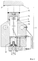
- FIG. 2 the cross section of a previous shearbar (3) deburring machine (10) described above for a better understanding of the invention described below is shown and is hereby explained.
- the shear bar housing (13) made of solid material machined on all sides is provided with a corresponding number of guide bores (14) with the pressure cylinder (12), in which the shear piston (4) with its screwed-on shear caps (16) can be individually moved up and down.
- the pressure of the compressed air in the pressure cylinder (12) must be so great that the high-strength shear edge (15) of the shear cap (16) with its surface of approximately 20 cm 2 is pressed so firmly against the lower surface of a workpiece (1) so that it does not slip over a flat, rigid cutting bit (2) when debinding.
- the aforementioned high pressure creates one of the deburring movements during deburring counteracting friction between the surface of the shear edge (15) and the lower surface of the Workpiece (1) that adds to the shear force actually required and the Surface pressure between the shear piston (4) and the guide bore (14) also with the noticeably poor leverage and the guide bore (14) deformed or very worn out.
- the length of the shear piston (4) is too enlarge and use replaceable, high-strength guide bushings (not shown).
- a workpiece (1) has a cutting bit (2) at the bottom and cutting beads (22) at the top, into which the so-called burr (23) is inserted to differentiate, then the lifting cylinders (9.2) are suppressed in the lifting frame (17) the pivot bearings (18) of the lower piston carrier (19) upwards against the lower surface of the workpiece (1) for debarking and at the same time the lifting frame (17) with the upper piston body (21) down on the surface of the workpiece (1) for beading by moving the shear carriage (5) with the hydraulic shear cylinders (7). If the workpiece (1) is turned over for transport reasons, ie with the cutting bit (2) upwards and the cutting beads (22) coming into the deburrer (23), it is also possible to safely debard and deflate.
- a hold-down device is not required for this bearer (23) if the contact pressure from below is higher than the proportional slab weight.
- Thick stones (24) are inserted between the lower and upper pivot bearings (19, 21) a smallest through opening for the workpiece (1) against the lifting cylinder (9) determine. Thus only the pressure in the piston bodies (19, 21) acts upon the debarking the shear pistons (4).
- a rotary drive (25) or rotary stop (26) sits on the pivot bearings (18 or 20) Adjust or to limit a setting angle between the shear piston (4) and Workpiece (1).
- the drive can also be used to turn the piston body (19 or 21) into a Serve repair or cleaning position.
- Figure 4 is a view of a simplified debarner (23), namely only from pivot bearings (18) on both sides in lifting frames (17) on both sides via 4 lifting cylinders (9) which can be lifted on the base plates (27) with lifting guides (28) for the piston body (19 ) consisting.
- this burr (23) bears with shear pistons (4) pressed against a workpiece (1) from below when the workpiece (1) is pulled over the piston body (19).
- the entire piston body (19) is pressurized via the air line (29) and all the pistons (4) are extended together.
- all of the shear pistons (4) have a lower air pressure are extended or become and when lifting the piston body (19) through the Lift cylinder (9) before each shearing operation on the lower surface of the workpiece (1) of the mold create the following surface.
- the piston body (19) according to the invention corresponding to the former shear bar (3), now consists of an unprocessed, thick-walled tube which acts as an unprocessed cylinder space for offset shear pistons (4).
- the shear piston (4) is made in one piece from a shaving head (30) with a shear edge (15), working piston (31) and piston shaft (32) and with a buffer ring (34) made of elastic material held by a snap ring (33) to prevent it from being pushed out Mistake.
- the difference surface between the working piston (31) and the piston skirt (32) represents the effective pressure surface (35) for pressing the shaving head (30) against the lower surface of the workpiece (1).
- the shear piston (4) is guided in the upper piston bush (36) and the lower one Piston bushing (37) with hexagon socket screws (38) of the same size Through holes of the piston body (19) are attached.
- the diameters of the various components in the shear piston area are chosen so that the shear piston (4) on the shaving head (30), ie pulled out from one side can be, at most the upper piston bushing (36) loosened and pulled out becomes.
- the invention described below will be a deburring machine to differentiate Exbarter called a more noise and dust generating, but inexpensive solution to the deburring task for flat workpieces.
- Figure 6 shows the structure of an exbarter according to the invention.
- the shock wave (40) is provided with eccentric shoulders, as shown in Figure 7 , so that it like a crankshaft or camshaft whirling the beating disks (41).
- pneumatic lifting elements (45) set To the entire bearer for security reasons outside the beard processing company to be able to lower and to absorb unwanted momentum, the same is on pneumatic lifting elements (45) set.
- the bearings (43) can be suspended on shock absorbers (46) in a bearing frame (47) on a base plate ( 48) think as shown in Figure 8 .
- Figure 9 shows possible shapes of the striking disc (41), which ranges from circles to oval, rhombus, square, polygonal to special shapes with striking edges and knobs.
- a shock wave (40) with a shock disc (41) can also be exposed vertically or almost vertically under the workpiece, that is to say eccentrically spinning.
- the shock wave (40) is offset and guided in a shock wave body (50) filled with higher air pressure in two bushings (49) provided with sealing rings, has a sliding coupling (52) at the rear end in a lantern (51) for the shifting transmission of Torque forces from a drive (44).
- the shoulder pushes the shock wave (40) upward due to the air pressure and the drive (44) brings the impact disc (41) to the eccentric stroke at the upper end, while by means of the bearings (43) the shock wave body (50) hits a stop (not shown) is brought into a suitable, small angle to the lower surface of the workpiece (1).
- the hurling impact disc (41) is now moved parallel to the cutting bit (2) by means of the slide (53) carrying the bearings (43) by the slide drive (55) in the form of a spindle in a slide guide (54).
- the impact disc (41) As shown in Figure 11 , as a brush with a clamping ring (56) and to form spring wires (57) or with clamping jaws (58) and spring wires (57).
- This version should be based on higher speeds at lower masses, but may have advantages with small beards and in the cost of wearing parts.
Landscapes
- Engineering & Computer Science (AREA)
- Mechanical Engineering (AREA)
- Physics & Mathematics (AREA)
- Optics & Photonics (AREA)
- Milling, Broaching, Filing, Reaming, And Others (AREA)
- Continuous Casting (AREA)
- Treatment Of Steel In Its Molten State (AREA)
Claims (6)
- Installation de coulée continue d'acier avec installation d'ébavurage des lingots ou des pièces des lingots, installée en ligne ou en sortie de ligne dans une installation de coulée continue d'acier, caractérisée en ce que des disques de frappe (41) d'un nombre correspondant à la largeur de la coulée sont rapportés sur un arbre de frappe (40) horizontal ou vertical, se présentant de préférence sous la forme d'un arbre à came et tournant à grande vitesse sous l'action d'un entraínement (44), que l'alésage central de ces disques de frappe est d'un diamètre bien supérieur à celui de l'arbre de frappe et que la différence entre ces deux diamètres est supérieure à la distance séparant la face inférieure de la pièce d'oeuvre à ébavurer (1) resp. la bavure (2) et les disques de frappe en position de repos.
- Installation de coulée continue d'acier avec installation d'ébavurage des lingots ou des pièces des lingots selon la revendication 1, caractérisée en ce que les disques de frappe (41) présentent un profit extérieur rond, oval, en losange, carré ou polygonal et sont pourvus de surfaces de frappe, d'ergots de frappe démontables ou de brosses de frappe montés sur le manteau extérieur ou la face frontale libre.
- Installation de coulée continue d'acier avec installation d'ébavurage des lingots ou des pièces des lingots selon l'une des revendications 1 et 2, caractérisée en ce que les paliers (43) sont installés sur des éléments de levée pneumatiques ou hydrauliques pour s'adapter à la position de la face inférieure de la pièce d'oeuvre (1).
- Installation de coulée continue d'acier avec installation d'ébavurage des lingots ou des pièces des lingots selon l'une des revendications 1 à 3, caractérisée en ce que les paliers (43) de l'arbre de frappe (40) sont maintenus par des amortisseurs classiques qui assurent de par leur arrangement et leur nombre une suspension efficace de l'ensemble.
- Installation de coulée continue d'acier avec installation d'ébavurage des lingots ou des pièces des lingots selon l'une des revendications 1 à 4, caractérisée en ce que les décalages excentriques de l'arbre de frappe (40) prévus pour lancer les disques de frappe (41) sont remplacés par une friction élevée entre les deux éléments.
- Installation de coulée continue d'acier avec installation d'ébavurage des lingots ou des pièces des lingots selon l'une des revendications 1 à 5, caractérisée en ce que l'arbre de frappe (40) pourvu d'un côté d'un disque de frappe (41) est monté dans un corps de frappe (50) pivotable qui assure la levée de l'arbre par air comprimé et que l'arbre de frappe est associé de l'autre côté à un entraínement (44) au moyen d'un accouplement coulissant (52).
Priority Applications (6)
| Application Number | Priority Date | Filing Date | Title |
|---|---|---|---|
| EP94104071A EP0672487B1 (fr) | 1994-03-16 | 1994-03-16 | Installation de coulée continue d'acier avec installation d'ébaburage des lingots ou des pièces des lingots |
| AT94104071T ATE172394T1 (de) | 1994-03-16 | 1994-03-16 | Stahlstranggiessanlage mit im einrichtung zum entbarten von strängen oder strangstücken |
| DE59407135T DE59407135D1 (de) | 1994-03-16 | 1994-03-16 | Stahlstranggiessanlage mit im Einrichtung zum Entbarten von Strängen oder Strangstücken |
| US08/403,370 US5597030A (en) | 1994-03-16 | 1995-03-15 | Apparatus for deburring flame cut slabs |
| JP7057764A JP2788422B2 (ja) | 1994-03-16 | 1995-03-16 | 酸素切断ばりを除去するインライン又はオフライン装置を有する連続鋳鋼設備 |
| US08/790,359 US5765271A (en) | 1994-03-16 | 1997-01-28 | Apparatus for deburring slabs |
Applications Claiming Priority (1)
| Application Number | Priority Date | Filing Date | Title |
|---|---|---|---|
| EP94104071A EP0672487B1 (fr) | 1994-03-16 | 1994-03-16 | Installation de coulée continue d'acier avec installation d'ébaburage des lingots ou des pièces des lingots |
Publications (2)
| Publication Number | Publication Date |
|---|---|
| EP0672487A1 EP0672487A1 (fr) | 1995-09-20 |
| EP0672487B1 true EP0672487B1 (fr) | 1998-10-21 |
Family
ID=8215776
Family Applications (1)
| Application Number | Title | Priority Date | Filing Date |
|---|---|---|---|
| EP94104071A Expired - Lifetime EP0672487B1 (fr) | 1994-03-16 | 1994-03-16 | Installation de coulée continue d'acier avec installation d'ébaburage des lingots ou des pièces des lingots |
Country Status (5)
| Country | Link |
|---|---|
| US (2) | US5597030A (fr) |
| EP (1) | EP0672487B1 (fr) |
| JP (1) | JP2788422B2 (fr) |
| AT (1) | ATE172394T1 (fr) |
| DE (1) | DE59407135D1 (fr) |
Cited By (3)
| Publication number | Priority date | Publication date | Assignee | Title |
|---|---|---|---|---|
| US6219894B1 (en) | 1998-08-19 | 2001-04-24 | Gega Corporation | Deburrer for continuous steel casting installation |
| US6277322B1 (en) | 1999-03-08 | 2001-08-21 | Gega Corporation | Deburring apparatus |
| DE102006042272A1 (de) * | 2006-09-08 | 2008-03-27 | Aute AG Gesellschaft für autogene Technik | Verfahren zum Brennschneiden von gegossenen Werkstücken und Einrichtung zum Entfernen von Sauerstoff-Schneidbärten an Werkstücken |
Families Citing this family (14)
| Publication number | Priority date | Publication date | Assignee | Title |
|---|---|---|---|---|
| DE59605139D1 (de) * | 1996-10-26 | 2000-06-08 | Lotz H K Feuerschutzbaustoffe | Entbartereinrichtung und -werkzeuge für Stahlstranggiessanlagen |
| EP0947264A3 (fr) * | 1997-04-21 | 1999-10-20 | AUTE Gesellschaft für autogene Technik mbH | Installation de coulée continue d'acier avec installation d'ébavurage |
| US5876162A (en) * | 1997-10-23 | 1999-03-02 | Keibler-Thompson Corporation | Apparatus for removing dross ridges from a metal workpiece |
| EP0947263A1 (fr) * | 1998-02-06 | 1999-10-06 | Aute AG Gesellschaft für autogene Technik | Machine pour enlever les bavures de la surface de billetes et brames causées par coupage thermochimique, en particulier dans et après une ligne de coulée continue d'acier |
| US6473952B1 (en) | 2000-10-13 | 2002-11-05 | Charles J. Gedrich | Deburrer device |
| KR20040022776A (ko) * | 2002-09-07 | 2004-03-18 | 주식회사 포스코 | 편심링을 이용한 스케일 고착 방지용 디스크 롤 |
| US7007737B2 (en) | 2003-09-30 | 2006-03-07 | Edw. C. Levy Co. | Slab handling apparatus |
| US7378051B2 (en) * | 2003-09-30 | 2008-05-27 | Edw. C. Levy Co. | Method and apparatus for slitting steel slabs |
| US20090265936A1 (en) * | 2008-04-24 | 2009-10-29 | Guido Baggioli | Process for manufacturing toothed sprockets for rewinding devices of safety belts |
| CN102848026A (zh) * | 2012-08-20 | 2013-01-02 | 吴江市三达五金工具厂 | 一种高效去毛刺机构 |
| CN107695172A (zh) * | 2017-09-25 | 2018-02-16 | 上海海隆石油管材研究所 | 摩擦焊外飞边冲切装置 |
| CN107824898B (zh) * | 2017-12-18 | 2024-02-27 | 鞍山威达机械工程有限公司 | 上下刮刀式去除钢坯端部毛刺的机构 |
| WO2020050664A1 (fr) * | 2018-09-05 | 2020-03-12 | 손현승 | Dispositif d'extraction du laitier |
| CN118848537B (zh) * | 2024-09-29 | 2024-11-29 | 内蒙古龙马风能装备有限公司 | 一种降尘无烟化环保型钢板切割设备 |
Family Cites Families (12)
| Publication number | Priority date | Publication date | Assignee | Title |
|---|---|---|---|---|
| FR1458948A (fr) * | 1965-04-12 | 1966-04-29 | Lorraine Escaut Sa | Dispositif pour raboter les rives d'un feuillard |
| US3515029A (en) * | 1968-08-30 | 1970-06-02 | Romain Gambini | Device for removing the burr from the ends of cylindrical parts |
| CH584067A5 (fr) * | 1974-03-15 | 1977-01-31 | Andreas E Dr Hazemag Kg | |
| AT371745B (de) * | 1979-06-26 | 1983-07-25 | Linsinger Ernst Dipl Ing Dr | Verfahren und werkzeug zum beseitigen des brenngrates an den kanten brenngeschnittener blechteile |
| EP0064083A4 (fr) * | 1980-11-11 | 1986-02-13 | Kawasaki Steel Co | Dispositif et procede d'extraction d'un laitier d'une piece en acier coupee par fusion. |
| FR2580203B1 (fr) * | 1985-04-12 | 1987-08-28 | Usinor | Machine d'ebavurage de brames |
| US4704241A (en) * | 1985-12-16 | 1987-11-03 | Allied Corporation | Deflashing method |
| SU1389946A1 (ru) * | 1985-12-24 | 1988-04-23 | Минское станкостроительное производственное объединение им.Октябрьской революции | Устройство дл сн ти заусенцев с кромок деталей |
| US4859126A (en) * | 1986-02-21 | 1989-08-22 | Keibler-Thompson Corp. | Apparatus and method for removing dross ridges from a metal workpiece |
| JPH03210951A (ja) * | 1990-01-17 | 1991-09-13 | Kawasaki Steel Corp | 連続鋳造鋳片の溶断ダレ除去方法及び装置 |
| EP0463201A1 (fr) * | 1990-06-25 | 1992-01-02 | AUTE Gesellschaft für autogene Technik mbH | Installation de coulée continue d'acier contenant un dispositif pour éliminer des bourrelets produits pendant le découpage à l'oxygène |
| DE9014962U1 (de) * | 1990-10-30 | 1991-01-10 | Plakoma Planungen und Konstruktionen von maschinellen Einrichtungen GmbH, 6638 Dillingen | Vorrichtung zum Entfernen von Brennbärten an Brennschneidkanten von Metallteilen |
-
1994
- 1994-03-16 DE DE59407135T patent/DE59407135D1/de not_active Expired - Fee Related
- 1994-03-16 EP EP94104071A patent/EP0672487B1/fr not_active Expired - Lifetime
- 1994-03-16 AT AT94104071T patent/ATE172394T1/de active
-
1995
- 1995-03-15 US US08/403,370 patent/US5597030A/en not_active Expired - Fee Related
- 1995-03-16 JP JP7057764A patent/JP2788422B2/ja not_active Expired - Lifetime
-
1997
- 1997-01-28 US US08/790,359 patent/US5765271A/en not_active Expired - Fee Related
Cited By (4)
| Publication number | Priority date | Publication date | Assignee | Title |
|---|---|---|---|---|
| US6219894B1 (en) | 1998-08-19 | 2001-04-24 | Gega Corporation | Deburrer for continuous steel casting installation |
| US6277322B1 (en) | 1999-03-08 | 2001-08-21 | Gega Corporation | Deburring apparatus |
| DE102006042272A1 (de) * | 2006-09-08 | 2008-03-27 | Aute AG Gesellschaft für autogene Technik | Verfahren zum Brennschneiden von gegossenen Werkstücken und Einrichtung zum Entfernen von Sauerstoff-Schneidbärten an Werkstücken |
| DE102006042272B4 (de) * | 2006-09-08 | 2008-05-15 | Aute AG Gesellschaft für autogene Technik | Verfahren zum Brennschneiden von gegossenen Werkstücken und Einrichtung zum Entfernen von Sauerstoff-Schneidbärten an Werkstücken |
Also Published As
| Publication number | Publication date |
|---|---|
| US5597030A (en) | 1997-01-28 |
| ATE172394T1 (de) | 1998-11-15 |
| US5765271A (en) | 1998-06-16 |
| JP2788422B2 (ja) | 1998-08-20 |
| JPH0839218A (ja) | 1996-02-13 |
| DE59407135D1 (de) | 1998-11-26 |
| EP0672487A1 (fr) | 1995-09-20 |
Similar Documents
| Publication | Publication Date | Title |
|---|---|---|
| EP0671230B1 (fr) | Installation de coulée continue d'acier contenant un système d'abavurage pour boutrelets engendrés pendant le découpage à l'oxygène de brames et lingots | |
| EP0672487A1 (fr) | Installation de coulée continue d'acier avec installation d'ébaburage des lingots ou des pièces des lingots | |
| DE3021568C2 (de) | Verfahren und Vorrichtung zum Entschlacken und Entgraten der Kanten brenngeschnittener Blechteile | |
| EP1172159B1 (fr) | Dispositif d'ébavurage mécanique pour des bavures engendrées pendant le découpage transversal et longitudinal à l'oxygène de pièces d'acier comme des brames, lingots et billettes | |
| EP2366482B1 (fr) | Outil d'entaille à plusieurs axes | |
| EP0463201A1 (fr) | Installation de coulée continue d'acier contenant un dispositif pour éliminer des bourrelets produits pendant le découpage à l'oxygène | |
| DE818316C (de) | Einrichtung zum Polieren von Glas | |
| EP0838287B1 (fr) | Dispositif et outil coupant d'ébavurage pour les installations de coulée continue | |
| DE1783057A1 (de) | Verfahren und Einrichtung zum Abtragen der Kanten von einem laenglichen Werkstueck,insbesondere zum Abrichten der Kanten von Stahlknueppeln oder Straengen einer Stranggussanlage | |
| EP2353751B1 (fr) | Système d'ébarbage pour l'enlèvement mécanique d'une barbe de coupe sur une pièce usinée coulée en continu | |
| DE4217530C2 (de) | Verfahren zum Bearbeiten von Kolbenlaufbahnen | |
| EP0947264A2 (fr) | Installation de coulée continue d'acier avec installation d'ébavurage | |
| EP0318701B1 (fr) | Procédé et dispositif pour la réparation des revêtements de poches métallurgiques | |
| DE1658304C3 (de) | Maschine zum Abschleifen des Schweißgrates von stumpfgeschweißten, nichtverlegten Schienen | |
| DE3120321C2 (de) | Verfahren und Vorrichtung zum Entgraten und Putzen von gußeisernen Rohrmuffen | |
| EP0947263A1 (fr) | Machine pour enlever les bavures de la surface de billetes et brames causées par coupage thermochimique, en particulier dans et après une ligne de coulée continue d'acier | |
| DE640817C (de) | Vorrichtung zum Schleifen von Fahrzeugschienen mit Hilfe einer am Umfang wirkenden Schleifscheibe | |
| DE474206C (de) | Schmiedemaschine | |
| EP0996845B1 (fr) | Procede et dispositif pour enlever et/ou oter en les brisant des couches ou des zones situees dans des substrats | |
| DE2346544C2 (de) | Verfahren und Vorrichtung zum geradlinigen Abtrennen von Werkstücken | |
| EP1228848A9 (fr) | Scie circulaire | |
| CN219852450U (zh) | 一种高度可调式板坯去毛刺机 | |
| DE814096C (de) | Verfahren und Vorrichtung zum Betrieb von Holzschleifern | |
| DE193276C (fr) | ||
| DE4332008A1 (de) | Schneidvorrichtung für dünnwandige Rohre |
Legal Events
| Date | Code | Title | Description |
|---|---|---|---|
| PUAI | Public reference made under article 153(3) epc to a published international application that has entered the european phase |
Free format text: ORIGINAL CODE: 0009012 |
|
| AK | Designated contracting states |
Kind code of ref document: A1 Designated state(s): AT DE GB NL |
|
| GBC | Gb: translation of claims filed (gb section 78(7)/1977) | ||
| RBV | Designated contracting states (corrected) |
Designated state(s): AT DE NL |
|
| 17P | Request for examination filed |
Effective date: 19960116 |
|
| 17Q | First examination report despatched |
Effective date: 19971031 |
|
| GRAG | Despatch of communication of intention to grant |
Free format text: ORIGINAL CODE: EPIDOS AGRA |
|
| GRAG | Despatch of communication of intention to grant |
Free format text: ORIGINAL CODE: EPIDOS AGRA |
|
| GRAH | Despatch of communication of intention to grant a patent |
Free format text: ORIGINAL CODE: EPIDOS IGRA |
|
| GRAG | Despatch of communication of intention to grant |
Free format text: ORIGINAL CODE: EPIDOS AGRA |
|
| GRAH | Despatch of communication of intention to grant a patent |
Free format text: ORIGINAL CODE: EPIDOS IGRA |
|
| GRAH | Despatch of communication of intention to grant a patent |
Free format text: ORIGINAL CODE: EPIDOS IGRA |
|
| RBV | Designated contracting states (corrected) |
Designated state(s): AT DE GB NL |
|
| GRAA | (expected) grant |
Free format text: ORIGINAL CODE: 0009210 |
|
| AK | Designated contracting states |
Kind code of ref document: B1 Designated state(s): AT DE GB NL |
|
| PG25 | Lapsed in a contracting state [announced via postgrant information from national office to epo] |
Ref country code: NL Free format text: LAPSE BECAUSE OF FAILURE TO SUBMIT A TRANSLATION OF THE DESCRIPTION OR TO PAY THE FEE WITHIN THE PRESCRIBED TIME-LIMIT Effective date: 19981021 |
|
| REF | Corresponds to: |
Ref document number: 172394 Country of ref document: AT Date of ref document: 19981115 Kind code of ref document: T |
|
| REF | Corresponds to: |
Ref document number: 59407135 Country of ref document: DE Date of ref document: 19981126 |
|
| GBT | Gb: translation of ep patent filed (gb section 77(6)(a)/1977) |
Effective date: 19981110 |
|
| PG25 | Lapsed in a contracting state [announced via postgrant information from national office to epo] |
Ref country code: GB Free format text: LAPSE BECAUSE OF NON-PAYMENT OF DUE FEES Effective date: 19990316 Ref country code: AT Free format text: LAPSE BECAUSE OF NON-PAYMENT OF DUE FEES Effective date: 19990316 |
|
| NLV1 | Nl: lapsed or annulled due to failure to fulfill the requirements of art. 29p and 29m of the patents act | ||
| PLBE | No opposition filed within time limit |
Free format text: ORIGINAL CODE: 0009261 |
|
| STAA | Information on the status of an ep patent application or granted ep patent |
Free format text: STATUS: NO OPPOSITION FILED WITHIN TIME LIMIT |
|
| 26N | No opposition filed | ||
| GBPC | Gb: european patent ceased through non-payment of renewal fee |
Effective date: 19990316 |
|
| PG25 | Lapsed in a contracting state [announced via postgrant information from national office to epo] |
Ref country code: DE Free format text: LAPSE BECAUSE OF NON-PAYMENT OF DUE FEES Effective date: 20000101 |