EP0673048A1 - Dispositif d'extinction d'arc à tôles d'extinction - Google Patents
Dispositif d'extinction d'arc à tôles d'extinction Download PDFInfo
- Publication number
- EP0673048A1 EP0673048A1 EP95100888A EP95100888A EP0673048A1 EP 0673048 A1 EP0673048 A1 EP 0673048A1 EP 95100888 A EP95100888 A EP 95100888A EP 95100888 A EP95100888 A EP 95100888A EP 0673048 A1 EP0673048 A1 EP 0673048A1
- Authority
- EP
- European Patent Office
- Prior art keywords
- arc
- quenching
- plates
- extinguishing
- plate
- Prior art date
- Legal status (The legal status is an assumption and is not a legal conclusion. Google has not performed a legal analysis and makes no representation as to the accuracy of the status listed.)
- Granted
Links
- 238000010791 quenching Methods 0.000 title claims description 45
- 230000000171 quenching effect Effects 0.000 title claims description 45
- 239000002184 metal Substances 0.000 claims description 4
- 238000013459 approach Methods 0.000 claims description 2
- 230000008033 biological extinction Effects 0.000 abstract 4
- 229910018503 SF6 Inorganic materials 0.000 description 2
- 230000000694 effects Effects 0.000 description 2
- 230000006872 improvement Effects 0.000 description 2
- 238000000034 method Methods 0.000 description 2
- 230000008569 process Effects 0.000 description 2
- SFZCNBIFKDRMGX-UHFFFAOYSA-N sulfur hexafluoride Chemical compound FS(F)(F)(F)(F)F SFZCNBIFKDRMGX-UHFFFAOYSA-N 0.000 description 2
- 229960000909 sulfur hexafluoride Drugs 0.000 description 2
- 230000009471 action Effects 0.000 description 1
- 230000008901 benefit Effects 0.000 description 1
- 230000008859 change Effects 0.000 description 1
- 238000010276 construction Methods 0.000 description 1
- 230000007480 spreading Effects 0.000 description 1
Images
Classifications
-
- H—ELECTRICITY
- H01—ELECTRIC ELEMENTS
- H01H—ELECTRIC SWITCHES; RELAYS; SELECTORS; EMERGENCY PROTECTIVE DEVICES
- H01H9/00—Details of switching devices, not covered by groups H01H1/00 - H01H7/00
- H01H9/30—Means for extinguishing or preventing arc between current-carrying parts
- H01H9/34—Stationary parts for restricting or subdividing the arc, e.g. barrier plate
- H01H9/36—Metal parts
Definitions
- the invention relates to an arc extinguishing device according to the preamble of claim 1.
- a known arc quenching device of this type is located together with an associated switch in a closed space filled with an electronegative quenching gas.
- the quenching plates assembled into a package are arranged one behind the other in the direction of movement of an arc-pulling switching piece of the switch in the event of a shutdown and offset in the longitudinal direction so that the distance between the arc-pulling end of the switching piece and the facing edges of the quenching plates in the course of Switch-off movement increases.
- a disadvantage of this arrangement is that due to the staggered arrangement of the quenching plates, the quenching plate stack is basically arranged in a diamond-shaped manner and is thus extended in the diagonal direction.
- the invention has for its object to take measures in an arc extinguishing device according to the preamble of claim 1, by means of which a substantial improvement of the arc extinguishing effect is achieved with simple means in a compact construction.
- an arc extinguishing device with perforated quenching plates, which are preferably made of expanded metal
- the quenching plates can be used in a cuboid arrangement and thus in the usual compact embodiment. In switching tests in the medium-voltage range at 24 kV, the cut-off power was increased from approximately 200 amperes to approximately 700 amperes in the case of a cuboidal fire-extinguishing plate arrangement.
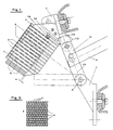
- a medium-voltage switch-disconnector 1 In a room (not shown) filled with an electronegative extinguishing gas, in particular sulfur hexafluoride (SF6), there is a medium-voltage switch-disconnector 1, the movable contact piece 1.1 of which is pivotally supported at one end about an axis 2 and whose switching piece end 1.2 is connected when an load current is switched off closed switching path with a fixed contact 1.3 is in an electrically conductive slide system.
- the contact piece 1 To open the switching path 1.2, 1.3, the contact piece 1 is pivoted away from the fixed contact 1.3 by means of a drive rod 3 which is articulated thereon, the free contact piece end 1.2 leaves the fixed contact piece 1.3 on an arc horn 1.4 provided thereon.
- SF6 sulfur hexafluoride
- the contact piece 1.1 In the direction of movement of the contact piece 1.1, adjacent to the arcing horn 1.4, there is a quenching plate packet 4 with individual quenching plates 5, which are arranged parallel to one another at a distance as a cuboid block.
- the quenching plates 5 lie one behind the other in the direction of movement of the switching element 1.1.
- the arc-pulling free contact piece end 1.2 only approaches the extinguishing plate edges located there after a predetermined swivel angle to a minimum distance a and moves away from the adjacent extinguishing plate edges during further swiveling.
- the longitudinal axis 1.5 of the movable contact piece 1.1 runs at the point of greatest proximity to the quenching plates 5 in a plane to which the quenching plates 5 lie in parallel planes.
- At least one of the quenching plates 5, but preferably all of them, are provided with a plurality of openings 6, which in particular are regularly distributed over the surface, as shown in FIG. 2.
- These quenching plates 5 are preferably made of expanded metal with diamond-shaped openings 6, the webs 7 surrounding the openings 6 being inclined with respect to the plane of the quenching plate.
- the center distance between adjacent quenching plates 5 is approximately 1/10 of the greatest edge length of the quenching plate 5 and is preferably approximately 7 mm.
- the extinguishing plates 5 can optionally have at their edge facing the contact 1.1 a cutout open towards the contact end 1.2, the width of which can be greater than the width of the free contact end 1.2.
- the contact piece 1.1 is preferably designed as a switch blade which is rotatably mounted at one end and which contacts the fixed contact piece 1.3 on opposite sides in order to achieve an optimal current transfer with a low contact resistance.
- the arc horn 1.4 runs in particular parallel to the adjacent first quenching plate of the quenching plate stack and is connected to it in a metallic and electrically conductive manner.
Landscapes
- Arc-Extinguishing Devices That Are Switches (AREA)
Applications Claiming Priority (2)
| Application Number | Priority Date | Filing Date | Title |
|---|---|---|---|
| DE4409495 | 1994-03-19 | ||
| DE4409495A DE4409495A1 (de) | 1994-03-19 | 1994-03-19 | Lichtbogenlöscheinrichtung mit Löschblechen |
Publications (2)
| Publication Number | Publication Date |
|---|---|
| EP0673048A1 true EP0673048A1 (fr) | 1995-09-20 |
| EP0673048B1 EP0673048B1 (fr) | 1998-04-01 |
Family
ID=6513296
Family Applications (1)
| Application Number | Title | Priority Date | Filing Date |
|---|---|---|---|
| EP95100888A Expired - Lifetime EP0673048B1 (fr) | 1994-03-19 | 1995-01-24 | Dispositif d'extinction d'arc à tÔles d'extinction |
Country Status (2)
| Country | Link |
|---|---|
| EP (1) | EP0673048B1 (fr) |
| DE (2) | DE4409495A1 (fr) |
Families Citing this family (1)
| Publication number | Priority date | Publication date | Assignee | Title |
|---|---|---|---|---|
| KR102819569B1 (ko) * | 2022-02-24 | 2025-06-11 | 엘에스일렉트릭(주) | 아크 슈트 및 이를 포함하는 부하 개폐기 |
Citations (5)
| Publication number | Priority date | Publication date | Assignee | Title |
|---|---|---|---|---|
| GB300575A (en) * | 1927-11-15 | 1929-10-03 | Siemens Ag | Improvements in or relating to electrical switches |
| FR1075587A (fr) * | 1953-02-27 | 1954-10-18 | Allis Chalmers Mfg Co | Perfectionnements relatifs à un interrupteur ou disjoncteur de circuit électrique |
| CH399564A (de) * | 1961-02-20 | 1965-09-30 | Licentia Gmbh | Lichtbogenlöschkammer für elektrische Schaltgeräte |
| EP0028012A1 (fr) * | 1979-10-27 | 1981-05-06 | Fuji Electric Co. Ltd. | Disjoncteur basse tension |
| EP0157242A2 (fr) * | 1984-04-04 | 1985-10-09 | Felten & Guilleaume Energietechnik AG | Dispositif d'extinction d'arc pour interrupteurs électriques de puissance |
Family Cites Families (6)
| Publication number | Priority date | Publication date | Assignee | Title |
|---|---|---|---|---|
| DE1040103B (de) * | 1957-03-20 | 1958-10-02 | Wissenschaftlich Tech Buero Fu | Loescheinsatz fuer elektrische Schaltgeraete |
| DE1126010B (de) * | 1960-09-16 | 1962-03-22 | Licentia Gmbh | Loeschblechanordnung fuer Niederspannungsschaltgeraete |
| DE3820489A1 (de) * | 1988-06-16 | 1989-12-21 | Felten & Guilleaume Energie | Gekapselte lasttrennschalteranordnung |
| DE3912726A1 (de) * | 1989-02-08 | 1990-08-09 | Siemens Ag | Lichtbogenloeschkammer mit loeschblechen |
| DE4141685C2 (de) * | 1991-12-18 | 1996-07-04 | Sachsenwerk Ag | Schaltanlage für Mittel- oder Hochspannung |
| DE4219673A1 (de) * | 1992-06-16 | 1993-12-23 | Emitec Emissionstechnologie | Metallträger aus Streckmetallband |
-
1994
- 1994-03-19 DE DE4409495A patent/DE4409495A1/de not_active Ceased
-
1995
- 1995-01-24 DE DE59501744T patent/DE59501744D1/de not_active Expired - Lifetime
- 1995-01-24 EP EP95100888A patent/EP0673048B1/fr not_active Expired - Lifetime
Patent Citations (5)
| Publication number | Priority date | Publication date | Assignee | Title |
|---|---|---|---|---|
| GB300575A (en) * | 1927-11-15 | 1929-10-03 | Siemens Ag | Improvements in or relating to electrical switches |
| FR1075587A (fr) * | 1953-02-27 | 1954-10-18 | Allis Chalmers Mfg Co | Perfectionnements relatifs à un interrupteur ou disjoncteur de circuit électrique |
| CH399564A (de) * | 1961-02-20 | 1965-09-30 | Licentia Gmbh | Lichtbogenlöschkammer für elektrische Schaltgeräte |
| EP0028012A1 (fr) * | 1979-10-27 | 1981-05-06 | Fuji Electric Co. Ltd. | Disjoncteur basse tension |
| EP0157242A2 (fr) * | 1984-04-04 | 1985-10-09 | Felten & Guilleaume Energietechnik AG | Dispositif d'extinction d'arc pour interrupteurs électriques de puissance |
Also Published As
| Publication number | Publication date |
|---|---|
| DE4409495A1 (de) | 1995-09-21 |
| EP0673048B1 (fr) | 1998-04-01 |
| DE59501744D1 (de) | 1998-05-07 |
Similar Documents
| Publication | Publication Date | Title |
|---|---|---|
| DE68909500T2 (de) | Strombegrenzender Selbstschalter für Niederspannung mit abgedichteter Schaltkammer. | |
| DE60030840T2 (de) | Leistungsschalter | |
| DE4410108C2 (de) | Lichtbogenlöschkammer mit drei Barrieren für den Durchtritt von Lichtbogengasen | |
| DE735829C (de) | Stromunterbrecher | |
| DE741695C (de) | Stromunterbrecher | |
| DE915358C (de) | Stromunterbrecher | |
| DE3872800T2 (de) | Schalteranordnung fuer elektrische mehrpolige schutzschalter mit mehreren kontakten. | |
| DE2441561A1 (de) | Schalt-teil eines druckgasschalters mit ausblasen des lichtbogens durch druckgas | |
| EP1032942B1 (fr) | Appareil de distribution muni d'un dispositif d'extinction d'arc | |
| DE10291133B4 (de) | Gehäuse für ein Schaltgerät | |
| DE672867C (de) | Schalter mit Lichtbogenloeschung durch stroemendes Druckgas | |
| DE1216964C2 (de) | Elektrischer schalter | |
| DE4243314A1 (de) | Strombegrenzender Schalter | |
| WO1993013538A1 (fr) | Coupe-circuit automatique comportant une boite d'extinction d'arc | |
| EP0959483B1 (fr) | Sectionneur de coupure en charge avec une chambre d'extinction | |
| EP0673048B1 (fr) | Dispositif d'extinction d'arc à tÔles d'extinction | |
| EP0051756B1 (fr) | Dispositif d'extinction d'arc éléctrique, notamment pour disjoncteur de protection | |
| DE68913403T2 (de) | Strombegrenzer. | |
| DE4041887A1 (de) | Lichtbogenkammer fuer ein elektrisches schaltgeraet | |
| DE3018254C2 (fr) | ||
| DE69009070T2 (de) | Hoch- oder Mittelspannungslastschalter. | |
| DE1182323B (de) | Elektrischer Schalter mit einem zur Lichtbogenloeschung dienenden Kamin | |
| DE4243537B4 (de) | Verfahren zum Schalten eines Sicherungslasttrenners und Sicherungslasttrenner hierzu | |
| EP0626708B1 (fr) | Disjoncteur sectionneur | |
| DE2923235A1 (de) | Fuer niederspannungsschaltanlagen bestimmter leistungsschalter oder schutzschalter mit in einer deionkammer angeordneten funkenloeschblechen |
Legal Events
| Date | Code | Title | Description |
|---|---|---|---|
| PUAI | Public reference made under article 153(3) epc to a published international application that has entered the european phase |
Free format text: ORIGINAL CODE: 0009012 |
|
| AK | Designated contracting states |
Kind code of ref document: A1 Designated state(s): DE FR GB IT NL SE |
|
| 17P | Request for examination filed |
Effective date: 19960214 |
|
| 17Q | First examination report despatched |
Effective date: 19970127 |
|
| GRAG | Despatch of communication of intention to grant |
Free format text: ORIGINAL CODE: EPIDOS AGRA |
|
| GRAG | Despatch of communication of intention to grant |
Free format text: ORIGINAL CODE: EPIDOS AGRA |
|
| GRAH | Despatch of communication of intention to grant a patent |
Free format text: ORIGINAL CODE: EPIDOS IGRA |
|
| GRAH | Despatch of communication of intention to grant a patent |
Free format text: ORIGINAL CODE: EPIDOS IGRA |
|
| GRAA | (expected) grant |
Free format text: ORIGINAL CODE: 0009210 |
|
| AK | Designated contracting states |
Kind code of ref document: B1 Designated state(s): DE FR GB IT NL SE |
|
| GBT | Gb: translation of ep patent filed (gb section 77(6)(a)/1977) |
Effective date: 19980402 |
|
| REF | Corresponds to: |
Ref document number: 59501744 Country of ref document: DE Date of ref document: 19980507 |
|
| ET | Fr: translation filed | ||
| ITF | It: translation for a ep patent filed | ||
| PG25 | Lapsed in a contracting state [announced via postgrant information from national office to epo] |
Ref country code: SE Free format text: LAPSE BECAUSE OF FAILURE TO SUBMIT A TRANSLATION OF THE DESCRIPTION OR TO PAY THE FEE WITHIN THE PRESCRIBED TIME-LIMIT Effective date: 19980701 |
|
| PLBE | No opposition filed within time limit |
Free format text: ORIGINAL CODE: 0009261 |
|
| STAA | Information on the status of an ep patent application or granted ep patent |
Free format text: STATUS: NO OPPOSITION FILED WITHIN TIME LIMIT |
|
| 26N | No opposition filed | ||
| REG | Reference to a national code |
Ref country code: GB Ref legal event code: IF02 |
|
| NLT1 | Nl: modifications of names registered in virtue of documents presented to the patent office pursuant to art. 16 a, paragraph 1 |
Owner name: ALSTOM SACHSENWERK GMBH |
|
| NLT1 | Nl: modifications of names registered in virtue of documents presented to the patent office pursuant to art. 16 a, paragraph 1 |
Owner name: AREVA SACHSENWERK GMBH |
|
| REG | Reference to a national code |
Ref country code: FR Ref legal event code: CD |
|
| REG | Reference to a national code |
Ref country code: FR Ref legal event code: CD |
|
| PGFP | Annual fee paid to national office [announced via postgrant information from national office to epo] |
Ref country code: IT Payment date: 20100125 Year of fee payment: 16 |
|
| PGFP | Annual fee paid to national office [announced via postgrant information from national office to epo] |
Ref country code: GB Payment date: 20100128 Year of fee payment: 16 |
|
| PGFP | Annual fee paid to national office [announced via postgrant information from national office to epo] |
Ref country code: NL Payment date: 20100121 Year of fee payment: 16 |
|
| PGFP | Annual fee paid to national office [announced via postgrant information from national office to epo] |
Ref country code: FR Payment date: 20110201 Year of fee payment: 17 Ref country code: DE Payment date: 20110322 Year of fee payment: 17 |
|
| REG | Reference to a national code |
Ref country code: NL Ref legal event code: V1 Effective date: 20110801 |
|
| GBPC | Gb: european patent ceased through non-payment of renewal fee |
Effective date: 20110124 |
|
| PG25 | Lapsed in a contracting state [announced via postgrant information from national office to epo] |
Ref country code: GB Free format text: LAPSE BECAUSE OF NON-PAYMENT OF DUE FEES Effective date: 20110124 |
|
| PG25 | Lapsed in a contracting state [announced via postgrant information from national office to epo] |
Ref country code: NL Free format text: LAPSE BECAUSE OF NON-PAYMENT OF DUE FEES Effective date: 20110801 Ref country code: IT Free format text: LAPSE BECAUSE OF NON-PAYMENT OF DUE FEES Effective date: 20110124 |
|
| REG | Reference to a national code |
Ref country code: FR Ref legal event code: ST Effective date: 20120928 |
|
| PG25 | Lapsed in a contracting state [announced via postgrant information from national office to epo] |
Ref country code: DE Free format text: LAPSE BECAUSE OF NON-PAYMENT OF DUE FEES Effective date: 20120801 |
|
| REG | Reference to a national code |
Ref country code: DE Ref legal event code: R119 Ref document number: 59501744 Country of ref document: DE Effective date: 20120801 |
|
| PG25 | Lapsed in a contracting state [announced via postgrant information from national office to epo] |
Ref country code: FR Free format text: LAPSE BECAUSE OF NON-PAYMENT OF DUE FEES Effective date: 20120131 |