EP0673716A1 - Dispositif pour le polissage de jetons de machines de jeu et la separation de l'abrasif desdits jetons - Google Patents
Dispositif pour le polissage de jetons de machines de jeu et la separation de l'abrasif desdits jetons Download PDFInfo
- Publication number
- EP0673716A1 EP0673716A1 EP91917816A EP91917816A EP0673716A1 EP 0673716 A1 EP0673716 A1 EP 0673716A1 EP 91917816 A EP91917816 A EP 91917816A EP 91917816 A EP91917816 A EP 91917816A EP 0673716 A1 EP0673716 A1 EP 0673716A1
- Authority
- EP
- European Patent Office
- Prior art keywords
- abrasive
- medals
- game machine
- polishing
- separating
- Prior art date
- Legal status (The legal status is an assumption and is not a legal conclusion. Google has not performed a legal analysis and makes no representation as to the accuracy of the status listed.)
- Withdrawn
Links
Images






Classifications
-
- B—PERFORMING OPERATIONS; TRANSPORTING
- B24—GRINDING; POLISHING
- B24B—MACHINES, DEVICES, OR PROCESSES FOR GRINDING OR POLISHING; DRESSING OR CONDITIONING OF ABRADING SURFACES; FEEDING OF GRINDING, POLISHING, OR LAPPING AGENTS
- B24B31/00—Machines or devices designed for polishing or abrading surfaces on work by means of tumbling apparatus or other apparatus in which the work and/or the abrasive material is loose; Accessories therefor
- B24B31/10—Machines or devices designed for polishing or abrading surfaces on work by means of tumbling apparatus or other apparatus in which the work and/or the abrasive material is loose; Accessories therefor involving other means for tumbling of work
-
- B—PERFORMING OPERATIONS; TRANSPORTING
- B24—GRINDING; POLISHING
- B24B—MACHINES, DEVICES, OR PROCESSES FOR GRINDING OR POLISHING; DRESSING OR CONDITIONING OF ABRADING SURFACES; FEEDING OF GRINDING, POLISHING, OR LAPPING AGENTS
- B24B31/00—Machines or devices designed for polishing or abrading surfaces on work by means of tumbling apparatus or other apparatus in which the work and/or the abrasive material is loose; Accessories therefor
- B24B31/12—Accessories; Protective equipment or safety devices; Installations for exhaustion of dust or for sound absorption specially adapted for machines covered by group B24B31/00
- B24B31/16—Means for separating the workpiece from the abrasive medium at the end of operation
Definitions
- the present invention relates to an apparatus for polishing game media, for example, medals for use in a game machine such as a slot machine and for separating an abrasive therefrom, in which the medals are polished while being lifted up together with the abrasive within a polishing machine, and in which the abrasive is there-after separated from the medals and returned to the polishing machine.
- a game machine such as a slot machine
- abrasive there-after separated from the medals and returned to the polishing machine.
- medals for a game machine such as a slot machine
- an abrasive are mixed and then stirred to polish the medals, and that the abrasive is thereafter separated from the medals and mixed with medals again for reuse.
- the prior art has involved the problem that, when the medals and the abrasive are accepted in order to polish the former by the stirring, excessive forces act on the medals to deform them.
- Another problem has been that a polishing machine increases in height due to requirements of the treatment and its external appearance does not blend well with the surroundings.
- a further problem has been that, since the abrasive for use is usually made of a plastic material, the abrasive becomes electrostatically charged in the polishing operation and sticks to the medals and is not easily separated therefrom in an abrasive separation unit.
- the present invention is intended to solve the problems as mentioned above and to provide an apparatus which can favorably perform the polishing and separating operations.
- the apparatus is so constructed that an intake port for accepting the medals and abrasive is provided on a lower end side of a polishing pipe set upright, while a medal delivery port is provided on an upper end side of the polishing pipe, that a rotatable screw element which lifts up the medals and abrasive while stirring them is mounted inside the polishing pipe, and that a separation unit which separates the abrasive from the medals and which permits the separated abrasive to be fed into the intake port is joined to an upper part of the polishing pipe.
- a flap which prevents the abrasive from splashing can be interposed at that position of the intake port which communicates with a lower part of a return pipe underlying the separation unit.
- the polishing pipe can be so formed that its lower portion is curved or crooked at an obtuse angle with respect to its upper portion which is vertically erected substantially straight, while a prime mover for driving the rotatable screw element can be disposed at an upper end of the polishing pipe.
- the intake port can be provided with a clearance between a lower end of the polishing pipe and that of the screw element, and pitches of the screw element can be formed so as to be smaller in a lower portion of the polishing pipe than in an upper portion thereof.
- the polishing pipe can be formed into a U-shape or Z-shape as viewed from the side, upper and lower corners of which are round crooked portions, and the separation unit which allows the abrasive to leak down can be mounted on the bottom of the polishing pipe near the upper round crooked portion.
- the separation unit can be furnished with a channel element for the medals, which communicates with the medal delivery port and which has abrasive passing apertures, and it can also be furnished with a rotatable sweep member or a rotatable screw member over an upper surface of the channel element.
- This channel element can be formed flat or semicylindrical.
- the sweep member can be constructed by forming a helical brush member on an outer periphery of a rotatable shaft.
- a rotatable sweep member having a helical brush member can be mounted on a shaft inside said channel element if the channel element is made cylindrical.
- the channel element can be rendered free to be driven and rotated.
- the separation unit can alternatively be furnished with a cylindrical or semicylindrical channel element, which communicates with the medal delivery port and which has abrasive passing apertures, and a rotatable vane element in which vane members are mounted round a shaft in staggered fashion can be disposed inside the separation unit.
- the separation unit can also be constructed by disposing a slant channel element inside a channel housing which communicates with the medal delivery port as well as a medal delivery portion, and mounting a rotatable sweep member on a shaft over an upper surface of the channel element which can be bent from an upper stream toward a lower stream thereof and the channel housing can have its bottom surface inclined to form a channel toward the intake port.
- the sweep member is constructed by being arranged in parallel or at right angles with a channel for the medals.
- the apparatus can regularly accept the medals from the intake port at the lower end of the polishing pipe while regulating the abrasive by means of the splash preventive flap so as not to be scattered about.
- the apparatus can lift up the medals while stirring them together with the abrasive, after having accepted these medals so as to prevent them from being deformed due to excessive forces or from being jammed midway in the interior of the polishing pipe.
- the polishing pipe is formed into the U-shape or Z-shape when viewed from the side, it can be formed into a low compact structure so as to harmonize with the surroundings, and the abrasive can be separated away from the bottom of the polishing pipe at and near the upper round crooked portion.
- the abrasive adhering to the medals is separated forcibly and reliably by the sweep member, whereby it can be favorably removed through the abrasive passing apertures.
- the removed abrasive can be fed into the intake port at the lower end of the polishing pipe so as to be reused.
- Fig. 1 is a side sectional view showing the essential portions of the first embodiment.
- Fig. 2 is a side sectional view showing the operating state of the embodiment in Fig. 1.
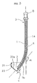
- Fig. 3 is a side sectional view showing the essential portions of the second embodiment.
- Fig. 4 is a perspective view showing a polishing apparatus furnished with the essential portions in Fig. 3.
- Fig. 5 is a side sectional view showing the essential portions of the third embodiment.
- Fig. 6 is a side view showing the essential portions of the fourth embodiment.
- Fig. 7 is a side sectional view showing the essential portions of the fifth embodiment.
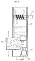
- Fig. 8 is a horizontal sectional view showing part of the embodiment in Fig. 7.
- Fig. 9 is a sectional view showing a section taken along line I - I in Fig. 7.
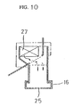
- Fig. 10 is a sectional view showing a section taken along line II - II in Fig. 9.
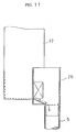
- Fig. 11 is a sectional view showing a section taken along line III - III in Fig. 7.
- Fig. 12 is a side sectional view showing the essential portions of the sixth embodiment.
- Fig. 13 is a left side view showing part of the embodiment in Fig. 12.
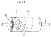
- Fig. 14 is a perspective view showing part of the embodiment in Fig. 12.
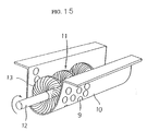
- Fig. 15 is a perspective view showing the essential portions of the seventh embodiment.
- FIGs. 1 and 2 illustrate the first embodiment.
- An intake port 2 which opens upwards facing a supply port 7 for medals is formed at the lower end of the curved lower side of a polishing pipe 1 set upright, while a medal delivery port 3 is formed in the side part of the upper end of the polishing pipe.
- a screw element 4 which is driven to rotate by a prime mover 8 mounted on the upper end of the polishing pipe 1, is inserted into this polishing pipe 1 and runs the full length thereof.
- a splash preventive flap 6 which is formed of a slit deflector made of a rubber sheet and which serves to prevent the abrasive from splashing outwards, is suspended from the upper position of the intake port 2 on the lower end side of the return pipe 5.
- the medals and the abrasive accepted from the intake port 2 are subjected to a polishing operation and are lifted up within the polishing pipe 1 while being stirred by the screw element 4.
- the medals and the abrasive delivered from the medal delivery port 3 are put on the screen 18, through which the latter leaks down.
- the abrasive having leaked down is fed from the return pipe 5 into the intake port 2, and is reused.
- the slit deflector made of the rubber sheet is provided so that, as the abrasive is being introduced below the return pipe, it may be prevented from splashing at the abrasive inlet and scattering out.
- the abrasive about to rush out collides against the deflector, and is kept in. Thus, the abrasive is smoothly accepted into the intake port.
- Figs. 3 and 4 illustrate the second embodiment, which is constructed similarly to the first embodiment as indicated by the same symbols, except to the following:
- the polishing pipe 1 over which the separation unit A is joined in communication therewith, is so formed that its lower portion 1b is curved or crooked at an obtuse angle ⁇ with respect to its upper portion 1a which is vertically erected and substantially straight.
- the pitches of the screw element 4 are formed so as to be smaller in the lower portion 1b than in the upper portion 1a.
- a medal reservoir 22 which is overlaid with an enclosure 20 and which has slots 21 for the medals in its outer periphery is joined in communication with the polishing pipe.
- the lower end of the screw element 4 is extended into the intake port 2 formed over the lower end side of the polishing pipe 1, so as to define a clearance C between it and the bottom 22a of the reservoir 22 serving as the lower end side of the polishing pipe 1.
- the third embodiment illustrated in Fig. 5 is so constructed that the bottom 22a of the reservoir 22 and the lower end of the screw element 4 are protruded frontwards beyond the inner corresponding position of the intake port 2.
- the polishing pipe 1 is formed so as to have the lower portion 1b curved or crooked at the obtuse angle ⁇ , the screw element 4 can accept the medals easily and convey them upwards without excessive force so as not to deform them.
- the clearance C is defined on the lower end side of the screw element 4, the medals are not subjected to excessive force and are not deformed due to the narrowed intervals of the medals on the lower end side of the polishing pipe 1, and they can be smoothly accepted.
- the pitches of the screw element 4 are varied, a conveyance force becomes smaller in the lower portion than in the upper portion, and the medals can be smoothly conveyed without being jammed halfway.
- Fig. 6 illustrates the fourth embodiment, which is constructed substantially similarly to the preceding embodiments as indicated by the same symbols, except the following:
- the polishing pipe 1 is formed into a U-shape in a side view, the upper and lower corners of which are rounded portions 1c, 1d.
- the prime mover 8 which is horizontal, is attached to the distal end of the upper part of the U-shape polishing pipe 1 which is mounted rotatable sideways through 90°.
- the filter of the separation unit A allowing the abrasive to leak down is mounted on the lower surface side of the polishing pipe 1 within a lateral range from the round position of the upper round crooked portion 1c, and the return pipe 5 is suspended from a recovery hopper 23 underlying the filter.
- a conveyance pipe 24 is extended from the medal delivery port 3 at the distal end of the part of the polishing pipe 1.
- this embodiment can be similarly constructed by forming the polishing pipe into a Z-shape in a side view.
- the polishing pipe 1 can be installed in the form of a compact structure so as to harmonize with surroundings and to avoid being large in size.
- the medals and the abrasive can be lifted up while being stirred by the screw element 4, and the abrasive can be separated in the upper part of the polishing pipe 1.
- a separation unit A disposed to the side of the upper part of a polishing pipe 1 includes a channel element 10, a sweep member 11, and a channel housing 17 in which the upper part of the polishing pipe 1 is inserted and which communicates with an upper medal delivery port 3 provided at the upper end of the polishing pipe 1.
- a medal delivery portion 16 is inserted below the medal delivery port 3, and a medal delivery port 25 is joined to the medal delivery portion 16 in communication therewith.
- the medal delivery portion 16 is a pipe for delivering the medals separated from the abrasive.
- the channel housing 17 is connected to an abrasive delivery box 26 as shown in Fig.
- the channel element 10 is a plate element which has abrasive passing apertures 9 adapted to pass only the abrasive therethrough, and it is preferably made up of a reticulate plate element.
- the channel element 10 consists of the first channel section 10a, second channel section 10b, third channel section 10c, fourth channel section 10d and fifth channel section 10e, which are bent and inclined from the lower stream side of the medal delivery port 3 down to the upper stream side of the medal delivery port 25.
- the first channel section 10a lies at the highest position and slopes downwards from just below the medal delivery port 3 toward an intake port 27, and it is provided at its intermediate part with a stepped portion 28 for shaking off the abrasive.
- the second channel section 10b slopes downwards from just beneath the first channel section 10a toward the polishing pipe 1, while the third channel section 10c slopes downwards from just below the second channel section 10b to the intake port 27.
- the fourth channel section 10d is joined to the intake port 27 in a manner to slope in an orthogonal direction (out of the sheet of the drawing as viewed in Fig. 7) to directions in which the medals flow on the first, second and third channel sections 10a, 10b and 10c.
- the fifth channel section 10e is arranged below the fourth channel section 10d in a manner to slope downwards from just beneath this section 10d to the medal delivery port 25 of the medal delivery portion 16.
- a guide plate 29 which guides down the abrasive falling through the first channel section 10a is suspended from near the upper most point of this channel section 10a.
- Partition channel sections 30a, 30b and 30c which have abrasive passing apertures similarly to the channel element are vertically mounted at the upper ends of the second, third and fifth channel sections 10b, 10c and 10e, respectively.
- Channel roof plates 31a and 31b which cause the abrasive to flow down are mounted aslant over the second and third channel sections 10b and 10c, respectively.
- a guide plate 32 is mounted aslant below the lower end of the third channel section 10c.
- the sweep member 11 is so constructed that a brush member 13 is helically wound on the outer periphery of a shaft 12 which is driven to rotate by a prime mover 33.
- This sweep member is held in contact with the upper surface of the first channel section 10a, and is disposed in the channel housing 17 so as to extend orthogonally to the flowing direction of the medals.
- slit flexible deflectors 34a and 34b, and 34c which extend orthogonally to the flowing directions of the medals are suspended over the first channel section 10a and over the fifth channel section 10e, respectively.
- the deflectors 34a, 34b and 34c are made of a material which is soft to the extent that the abrasive remaining on first channel section 10a and the fifth channel section 10e can be prevented from splashing downstream, while at the same time, the medals are not hindered from flowing even when a large number of them have flowed down to these deflectors.
- the medals and the abrasive delivered from the medal delivery port 3 at the upper end of the polishing pipe 1 flow as indicated by solid and dotted line arrows in the figures, respectively.
- the medals and the abrasive are delivered around the medal delivery port 3 as shown in Fig. 8. Therefore, the medals and the abrasive disperse more than in the case of delivering them in only one direction, so that the abrasive is separated from the medals more effectively.
- the medals and the abrasive having dropped onto the first channel section 10a slide downstream directly, the abrasive falling through the abrasive passing apertures 9 is guided by the guide plate 29.
- the medals flowing on the first channel section 10a have their surfaces swept by the brush member 13 of the rotated sweep member 11, so that the abrasive stuck to the surfaces of the medals by electrostatic charges etc. is swept off.
- the abrasive swept off leaks down through the first channel section 10a, whereby the medals and the abrasive can be favorably separated.
- the deflectors 34a and 34b prevent the remaining abrasive on the first channel section 10a from splashing downstream.
- the medals flow from the first channel section 10a to the second channel section 10b and then to the third channel section 10c so as to be accepted from the intake port 27.
- the abrasive is separated from the medals, not only by the abrasive passing apertures 9 of the first channel section 10a, but also by those of each of the partition channel section 30a, the second channel section 10b, the partition channel section 30b, the third channel section 10c, the fourth channel section 10d, the partition channel section 30c and the fifth channel section 10e.
- the first ⁇ fifth channel sections 10a ⁇ 10e are bent forming a long channel from the uppermost position to the lowermost position.
- the abrasive which splashes up from the tokens can be separated by the partition channel sections 30a, 30b and 30c.
- the deflector 34c prevents the remaining abrasive on the fifth channel section 10e from splashing downstream. Further, since the abrasive falling onto the channel roof plates 31a and 31b is directly caused to flow down, it can be prevented from mixing with the medals within the channel again.
- the abrasive separated from the medals falls to be introduced from the bottom of the channel housing 17 into the abrasive delivery box 26, whereupon it can be returned through the return pipe 5 into the intake port provided in the lower part of the polishing pipe 1.
- the bottom of the channel housing 17 is inclined to form a channel for the abrasive, the abrasive is recovered with ease.
- a separation unit A includes an upper stream casing 35, a channel element 10, a lower stream casing 36, a prime mover 37 and a sweep member 11.
- the upper stream casing 35 has a medal intake port 38 and a medal delivery port 39 in its side parts.
- the channel element 10 is cylindrical, and it is formed with abrasive passing apertures 9 in the whole peripheral surface thereof and has an entrance 40 and an exit 41 on both the end sides thereof.
- the lower stream casing 36 has an opening 42 in its side part, and a medal delivery portion 43 at its lower part.
- the upper stream casing 35, the channel element 10 and the lower stream casing 36 are joined in communication.
- the sweep member 11 is arranged in the channel element 10.
- a brush member 13 is radially formed around a helical core 44 disposed along the axis of the channel element 10, that the helical core 44 is wound and fixed round a shaft 12 which is driven to rotate by the prime mover 37, and that the brush member 13 is mounted so as to rotate in contact with the inner peripheral surface of the channel element 10.
- a wire gauze 46 is spread below the sweep member 11 at the lower part of the upper stream casing 35, an abrasive catcher 47 is mounted aslant under the wire gauze 46 as well as the channel element 10, and an abrasive takeout portion 49 whose lower part is closed by a cap 48 is suspended from the bottom part of the abrasive catcher 47.
- medals and an abrasive delivered from a polishing pipe are fed into the medal intake port 38 of the upper stream casing 35, they flow as indicated by solid and broken line arrows in Fig. 12.
- part of the abrasive is separated by the wire gauze 46, and the medals and the remaining abrasive are sent into the channel element 10 by the sweep member 11.
- the brush member 13 rotated in contact with the inner peripheral surface of the channel element 10 sweeps off the abrasive through the abrasive passing apertures 9 while stirring the medals and the abrasive together.
- the abrasive received in the abrasive catcher 47 can be taken out of the abrasive takeout portion 49 by detaching the cap 48.
- the medals sent into the channel element 10 by the sweep member 11 are delivered and dropped from the exit 41 into the lower stream casing 36, and they are thereafter taken out of the medal delivery portion 43.
- the separation apparatus of the sixth embodiment can construct one independent apparatus, and it can also be substituted for the structure of the fifth embodiment as shown in Fig. 11.
- the medal intake port 38 of the upper stream casing 35 is connected to the intake port 27 shown in Figs. 7 and 11, and the medal delivery portion 16 shown in Figs. 9 and 10 can be replaced with the medal delivery portion 43 of the lower stream casing 36.
- the abrasive can be separated more reliably without enlarging the separation unit in the sixth embodiment.
- the channel element 10 can be constructed so as to be driven and rotated about the axis thereof. In this case, the abrasive is returned by a pipe 5 instead of the cap 48.
- Fig. 15 illustrates the seventh embodiment.
- This embodiment is so constructed that a channel element 10 is formed to be semicylindrical and is formed with flange portions 50 on both sides of the upper part thereof, and that a sweep member 11 formed by helically winding a brush member 13 on the outer periphery of a shaft 12 is disposed in the semicylindrical channel element 10 which has abrasive passing apertures 9 over its whole surface. It can operate similarly to the sixth embodiment.
- the sweep member or the rotary vane member may well be replaced with a helical member.
- the helical member can be formed by winding, for example, a helical component made of rubber, metal such as sheet metal, or plastic such as duracon round the shaft instead of the brush member in the foregoing embodiment.
- the abrasive is expelled while being rotated together with the medals by this helical member.
- the distance which the medals and the abrasive advance on the channel is lengthened, and the abrasive is sifted off through the abrasive passing apertures at a higher degree.
- the channel element can be constructed of, for example, so-called expanded metal, an NC circular-hole plate, punching metal, or a metal gauze.
- the helical member is made of rubber, metal, plastic or the like, it may well be rotated together with the channel element 10 unlike the rotation of this helical member only.
- medals and an abrasive can be regularly accepted from an intake port 2 at the lower end of a polishing pipe 1 while the abrasive is being regulated by a splash preventive flap 6 so as not to scatter about and to hinder the supply of the medals.
- the medals can be favorably accepted so as not to be deformed due to excessive forces or to be jammed in the polishing pipe 1, and they can be lifted up while being stirred with the abrasive.
- the polishing pipe 1 When the polishing pipe 1 is formed into a U-shape or Z-shape in a side view, it can be suitably installed in the form of a low compact structure so as to harmonize with surroundings, and besides, the abrasive can be favorably separated through a bottom surface at and near an upper rounded portion 1c. Moreover, while the medals and the abrasive delivered from a medal delivery port 3 are kept flowing along a channel element 10, the abrasive adhering to the medals can be separated forcibly and reliably by a sweep member 11, a rotary vane member 14 or a helical member, to thereby be favorably removed through abrasive passing apertures 9.
Landscapes
- Engineering & Computer Science (AREA)
- Mechanical Engineering (AREA)
- Finish Polishing, Edge Sharpening, And Grinding By Specific Grinding Devices (AREA)
- Pinball Game Machines (AREA)
Applications Claiming Priority (5)
| Application Number | Priority Date | Filing Date | Title |
|---|---|---|---|
| JP61707/91 | 1991-03-26 | ||
| JP6170791A JP2753572B2 (ja) | 1991-03-26 | 1991-03-26 | 遊技媒体研磨装置 |
| JP3215619A JP2841133B2 (ja) | 1991-08-27 | 1991-08-27 | 遊技機用メダルの研磨及び研磨材分離装置 |
| JP215619/91 | 1991-08-27 | ||
| PCT/JP1991/001432 WO1992017316A1 (fr) | 1991-03-26 | 1991-10-18 | Dispositif pour le polissage de jetons de machines de jeu et la separation de l'abrasif desdits jetons |
Publications (2)
| Publication Number | Publication Date |
|---|---|
| EP0673716A4 EP0673716A4 (fr) | 1994-09-01 |
| EP0673716A1 true EP0673716A1 (fr) | 1995-09-27 |
Family
ID=26402767
Family Applications (1)
| Application Number | Title | Priority Date | Filing Date |
|---|---|---|---|
| EP91917816A Withdrawn EP0673716A1 (fr) | 1991-03-26 | 1991-10-18 | Dispositif pour le polissage de jetons de machines de jeu et la separation de l'abrasif desdits jetons |
Country Status (6)
| Country | Link |
|---|---|
| US (1) | US5487696A (fr) |
| EP (1) | EP0673716A1 (fr) |
| KR (1) | KR100187921B1 (fr) |
| AU (2) | AU655783B2 (fr) |
| CA (1) | CA2107117C (fr) |
| WO (1) | WO1992017316A1 (fr) |
Family Cites Families (16)
| Publication number | Priority date | Publication date | Assignee | Title |
|---|---|---|---|---|
| US2760504A (en) * | 1953-02-18 | 1956-08-28 | Syntron Co | In and out spiral trough parts cleaner |
| US3038186A (en) * | 1958-09-18 | 1962-06-12 | Master Machine Corp Of San Die | Golf ball washing machine having hopper means for feeding balls and liquid thereto |
| JPS5072285A (fr) * | 1973-08-16 | 1975-06-14 | ||
| JPS5172076A (ja) * | 1975-02-13 | 1976-06-22 | Soichi Takemoto | Ryujobutsuhansosochi |
| JPS5391278A (en) * | 1977-06-06 | 1978-08-10 | Souichi Takemoto | Apparatus for carrying particle material |
| JPS6043266A (ja) * | 1983-08-17 | 1985-03-07 | Mitsubishi Electric Corp | 信号記録再生方式 |
| JPS6043266U (ja) * | 1983-08-29 | 1985-03-27 | 株式会社 エ−ス電研 | パチンコ球の浄化装置 |
| JPS60103676A (ja) * | 1983-11-11 | 1985-06-07 | Seiko Instr & Electronics Ltd | 薄膜トランジスタアレイの製造方法 |
| US4803811A (en) * | 1985-07-09 | 1989-02-14 | Siemens Aktiengesellschaft | Lapping device for surface enhancement of bulk material |
| JPH01126291A (ja) * | 1987-11-10 | 1989-05-18 | Nec Corp | 輻射線加熱装置 |
| US4987702A (en) * | 1988-10-31 | 1991-01-29 | Seymour Foods, Inc. | Surfacing machine |
| GB2231804B (en) * | 1989-05-15 | 1993-05-12 | Ace Denken Kk | A method of an apparatus for continuously cleaning and polishing game balls |
| KR900017627A (ko) * | 1989-05-20 | 1990-12-19 | 다카토시 다케모토 | 빠찡꼬 구슬의 정화방법 및 장치 |
| US4970746A (en) * | 1990-02-07 | 1990-11-20 | Brackmann Rogers F | Golf ball washer |
| US5214883A (en) * | 1990-11-07 | 1993-06-01 | United Technologies Corporation | Method and apparatus for processing articles requiring a surface finish |
| JPH0643266A (ja) * | 1990-12-29 | 1994-02-18 | Casio Comput Co Ltd | 電子時計 |
-
1991
- 1991-10-18 CA CA002107117A patent/CA2107117C/fr not_active Expired - Fee Related
- 1991-10-18 WO PCT/JP1991/001432 patent/WO1992017316A1/fr not_active Ceased
- 1991-10-18 KR KR1019930702897A patent/KR100187921B1/ko not_active Expired - Fee Related
- 1991-10-18 US US08/119,246 patent/US5487696A/en not_active Expired - Fee Related
- 1991-10-18 EP EP91917816A patent/EP0673716A1/fr not_active Withdrawn
- 1991-10-18 AU AU87137/91A patent/AU655783B2/en not_active Ceased
-
1994
- 1994-10-28 AU AU77597/94A patent/AU670008B2/en not_active Ceased
Also Published As
| Publication number | Publication date |
|---|---|
| AU7759794A (en) | 1995-02-16 |
| CA2107117C (fr) | 1997-04-29 |
| EP0673716A4 (fr) | 1994-09-01 |
| AU655783B2 (en) | 1995-01-12 |
| AU670008B2 (en) | 1996-06-27 |
| WO1992017316A1 (fr) | 1992-10-15 |
| US5487696A (en) | 1996-01-30 |
| KR100187921B1 (ko) | 1999-06-01 |
| CA2107117A1 (fr) | 1992-09-27 |
| AU8713791A (en) | 1992-11-02 |
Similar Documents
| Publication | Publication Date | Title |
|---|---|---|
| US5326312A (en) | Coin/token dispensing unit | |
| DE4439401A1 (de) | Schwingungsangeregter Einfüllbehälter zum Abgeben eines Produkts | |
| JP3628559B2 (ja) | ビーズミル | |
| AU7705794A (en) | Materials mixer | |
| US5487696A (en) | Apparatus for polishing medals for game machine and for separating abrasive therefrom | |
| JP3171892B2 (ja) | パチンコ玉回収樋 | |
| US20010006883A1 (en) | Coin dispenser assembly with improved coin transport surfaces | |
| JP2841133B2 (ja) | 遊技機用メダルの研磨及び研磨材分離装置 | |
| EP0690419A1 (fr) | Dispositif pour distribuer des pièces d'argent | |
| JP3919865B2 (ja) | パチンコ機の球タンク | |
| RU2114701C1 (ru) | Способ обогащения мелкофракционной рудной массы | |
| JPH0617462Y2 (ja) | メタル磨装置 | |
| JPH0446851B2 (fr) | ||
| JPH0880378A (ja) | パチンコ球の揚送研磨装置 | |
| JPH049655Y2 (fr) | ||
| JP2860619B2 (ja) | メダル浄化装置 | |
| EP0442696A1 (fr) | Appareil de distribution de pièces | |
| JP2878234B2 (ja) | パチンコホールにおける球循環装置 | |
| JPH0245468B2 (fr) | ||
| KR200393299Y1 (ko) | 승강기형 곡물이송장치 | |
| JP2689044B2 (ja) | パチンコ球の揚送研磨装置 | |
| JP2753572B2 (ja) | 遊技媒体研磨装置 | |
| JP2657729B2 (ja) | パチンコ球の揚送研磨装置 | |
| JP3037227U (ja) | パチンコ玉払出し装置 | |
| JP6918340B2 (ja) | パチンコ球研磨揚送装置 |
Legal Events
| Date | Code | Title | Description |
|---|---|---|---|
| A4 | Supplementary search report drawn up and despatched | ||
| AK | Designated contracting states |
Kind code of ref document: A4 Designated state(s): DE FR GB |
|
| PUAI | Public reference made under article 153(3) epc to a published international application that has entered the european phase |
Free format text: ORIGINAL CODE: 0009012 |
|
| 17P | Request for examination filed |
Effective date: 19931025 |
|
| AK | Designated contracting states |
Kind code of ref document: A1 Designated state(s): DE FR GB |
|
| 17Q | First examination report despatched |
Effective date: 19960918 |
|
| STAA | Information on the status of an ep patent application or granted ep patent |
Free format text: STATUS: THE APPLICATION IS DEEMED TO BE WITHDRAWN |
|
| 18D | Application deemed to be withdrawn |
Effective date: 19970129 |