EP0674068B1 - Klammer zum Verbinden von Schaltafeln mit deren Randprofile zusammendrückenden Spannbacken - Google Patents
Klammer zum Verbinden von Schaltafeln mit deren Randprofile zusammendrückenden Spannbacken Download PDFInfo
- Publication number
- EP0674068B1 EP0674068B1 EP94120651A EP94120651A EP0674068B1 EP 0674068 B1 EP0674068 B1 EP 0674068B1 EP 94120651 A EP94120651 A EP 94120651A EP 94120651 A EP94120651 A EP 94120651A EP 0674068 B1 EP0674068 B1 EP 0674068B1
- Authority
- EP
- European Patent Office
- Prior art keywords
- wedge
- jaws
- clamp according
- engagement
- point
- Prior art date
- Legal status (The legal status is an assumption and is not a legal conclusion. Google has not performed a legal analysis and makes no representation as to the accuracy of the status listed.)
- Expired - Lifetime
Links
- 238000009415 formwork Methods 0.000 claims description 40
- 238000006073 displacement reaction Methods 0.000 description 6
- 230000013011 mating Effects 0.000 description 4
- 230000002349 favourable effect Effects 0.000 description 3
- 230000007704 transition Effects 0.000 description 3
- 239000011324 bead Substances 0.000 description 2
- 238000010276 construction Methods 0.000 description 2
- 230000000694 effects Effects 0.000 description 2
- 238000004519 manufacturing process Methods 0.000 description 2
- 230000000149 penetrating effect Effects 0.000 description 2
- 230000004308 accommodation Effects 0.000 description 1
- 230000005540 biological transmission Effects 0.000 description 1
- 238000006243 chemical reaction Methods 0.000 description 1
- 230000003247 decreasing effect Effects 0.000 description 1
- 238000001514 detection method Methods 0.000 description 1
- 230000002996 emotional effect Effects 0.000 description 1
- 238000005516 engineering process Methods 0.000 description 1
- 238000003780 insertion Methods 0.000 description 1
- 230000037431 insertion Effects 0.000 description 1
- 230000003993 interaction Effects 0.000 description 1
- 239000006228 supernatant Substances 0.000 description 1
- 230000001360 synchronised effect Effects 0.000 description 1
Images
Classifications
-
- E—FIXED CONSTRUCTIONS
- E04—BUILDING
- E04G—SCAFFOLDING; FORMS; SHUTTERING; BUILDING IMPLEMENTS OR AIDS, OR THEIR USE; HANDLING BUILDING MATERIALS ON THE SITE; REPAIRING, BREAKING-UP OR OTHER WORK ON EXISTING BUILDINGS
- E04G7/00—Connections between parts of the scaffold
- E04G7/02—Connections between parts of the scaffold with separate coupling elements
- E04G7/04—Flexible elements, with or without brackets, e.g. ropes, cables, chains
-
- E—FIXED CONSTRUCTIONS
- E04—BUILDING
- E04G—SCAFFOLDING; FORMS; SHUTTERING; BUILDING IMPLEMENTS OR AIDS, OR THEIR USE; HANDLING BUILDING MATERIALS ON THE SITE; REPAIRING, BREAKING-UP OR OTHER WORK ON EXISTING BUILDINGS
- E04G17/00—Connecting or other auxiliary members for forms, falsework structures, or shutterings
- E04G17/04—Connecting or fastening means for metallic forming or stiffening elements, e.g. for connecting metallic elements to non-metallic elements
- E04G17/045—Connecting or fastening means for metallic forming or stiffening elements, e.g. for connecting metallic elements to non-metallic elements being tensioned by wedge-shaped elements
-
- E—FIXED CONSTRUCTIONS
- E04—BUILDING
- E04G—SCAFFOLDING; FORMS; SHUTTERING; BUILDING IMPLEMENTS OR AIDS, OR THEIR USE; HANDLING BUILDING MATERIALS ON THE SITE; REPAIRING, BREAKING-UP OR OTHER WORK ON EXISTING BUILDINGS
- E04G9/00—Forming or shuttering elements for general use
- E04G9/02—Forming boards or similar elements
- E04G2009/023—Forming boards or similar elements with edge protection
- E04G2009/025—Forming boards or similar elements with edge protection by a flange of the board's frame
-
- Y—GENERAL TAGGING OF NEW TECHNOLOGICAL DEVELOPMENTS; GENERAL TAGGING OF CROSS-SECTIONAL TECHNOLOGIES SPANNING OVER SEVERAL SECTIONS OF THE IPC; TECHNICAL SUBJECTS COVERED BY FORMER USPC CROSS-REFERENCE ART COLLECTIONS [XRACs] AND DIGESTS
- Y10—TECHNICAL SUBJECTS COVERED BY FORMER USPC
- Y10T—TECHNICAL SUBJECTS COVERED BY FORMER US CLASSIFICATION
- Y10T24/00—Buckles, buttons, clasps, etc.
- Y10T24/44—Clasp, clip, support-clamp, or required component thereof
- Y10T24/44291—Clasp, clip, support-clamp, or required component thereof including pivoted gripping member
- Y10T24/44342—Clasp, clip, support-clamp, or required component thereof including pivoted gripping member having rigid linking arm pivotally connected to each gripping member
-
- Y—GENERAL TAGGING OF NEW TECHNOLOGICAL DEVELOPMENTS; GENERAL TAGGING OF CROSS-SECTIONAL TECHNOLOGIES SPANNING OVER SEVERAL SECTIONS OF THE IPC; TECHNICAL SUBJECTS COVERED BY FORMER USPC CROSS-REFERENCE ART COLLECTIONS [XRACs] AND DIGESTS
- Y10—TECHNICAL SUBJECTS COVERED BY FORMER USPC
- Y10T—TECHNICAL SUBJECTS COVERED BY FORMER US CLASSIFICATION
- Y10T24/00—Buckles, buttons, clasps, etc.
- Y10T24/44—Clasp, clip, support-clamp, or required component thereof
- Y10T24/44291—Clasp, clip, support-clamp, or required component thereof including pivoted gripping member
- Y10T24/44496—Clasp, clip, support-clamp, or required component thereof including pivoted gripping member with operator means for moving pivoted member
- Y10T24/44513—Camming or wedging element
Definitions
- the invention relates to a clamp for connecting in one plane side-by-side formwork panels according to the preamble of Claim 1.
- Such a bracket is from DE-U-88 14 208 and EP-B1-0 369 197 known and has especially known for the simplicity of the Operation with effective creation of the desired one Proven clamping force.
- An eccentric is used as the actuating element provided with an operating lever whose axis of rotation at the same time can also be moved at right angles to the formlining to make it rotatable is. If this eccentric is rotated, it causes its adjustment A corresponding adjustment at the same time as the swivel and swivel bearings of the two adjustment legs that are in the area of this turning and Pivot bearing can be detected by the eccentric.
- the pivoting the adjustment leg away from the formlining at the same time the pivoting of the jaws against the one to be connected Edge profiles. This represents a very easy to use bracket represents.
- DE-A-38 23 763 in turn shows a bracket of another type, in which a tensioning or operating lever is in the tensioning position protruding from the bracket and the panel is avoided.
- two jaws connected by a single joint provided that move away from each other starting from the joint and are attacked by a pressure bar in this area, which receives the clamping legs in corresponding recesses.
- This Pressure bar is adjustable by a parallel to the swivel axis Wedge forcibly moved and should thereby open the jaws or close. So are as an actuating or adjusting element two interacting and against each other during their operation rubbing parts necessary, namely the wedge and on the other hand the pressure bar.
- the clamping jaws a shape suitable for their interaction with the pressure beam and the wedge must have a double-T cross-section and thus have interacting guides. Manufacture and assembly of these Due to these requirements, brackets are to be regarded as complex.
- DE-U-80 09 045 describes a device for connecting other formwork panels arranged side by side are known, namely a bolt that penetrates the edge webs of two formwork panels and presses against each other by a tensile force applied to it.
- This Traction can either be by using a on the bolt through a Cross pin mounted eccentric or with the help of a bolt a wedge arranged through it or with the help a thread on the bolt are applied.
- bracket it’s not a swivel, the adjoining edge profiles compressing clamping jaws available.
- a wedge is a commonly used in formwork technology Tools for applying clamping or clamping forces, so that very easy operability is achieved. Because the wedge is on Attack points of adjustment legs of the two jaws attacks, the forces emanating from him when striking targeted and largely evenly transferred to both jaws be, even if the clear distance between the jaws themselves to Detection of edge profiles consisting of hollow profiles is very large should be. In addition, a wedge shows very well whether it is struck or not, that is, the clamping position control yourself in a simple way. The assembly is also very simply because a simple hammer blow is enough to close it the bracket to start and perform. The same goes for for releasing the clip.
- the points of attack for the designed as an actuating element wedge on the pivot bearing ends of the adjusting elements facing away from the two clamping jaws arranged and in particular at a matching point common attack point are provided. So the wedge serving as an actuating element does not have several different ones Act on and press attack points, but the wedge force is applied in one place and therefore to both Transfer actuation points of the two jaws, resulting in a largely uniform pivoting of both jaws leads.
- the abutment area for the wedge does not have to be opposite a line connecting the two swivel bearings of the jaws at an angle be arranged, as is the case with the clip according to DE-42 36 070 A1 due to the large distance between the operating points and in this direction decreasing width of the wedge is required.
- the wedge can displace a single part at a certain point and thereby two adjustment legs away from the formwork and thereby the jaws against the edge profiles to be connected swivel.
- the clamping force can be chosen more or less arbitrarily.
- too much clamping force cannot be generated because an eccentric is not rotated with a corresponding lever arm, which lever arm possibly even to exert a great force could still be extended.
- the clamping force is rather more or less precisely by the wedge and its helix angle given.
- the game in the connection area of the two Adjustment leg allows their mutual minor Pivoting on arcs while the connecting element itself adjusted more or less at right angles to the formlining becomes when the wedge attacks it more and more.
- connecting element as Connecting bolt is formed. This is a simple part on which the wedge can also grip well.
- the cross section of the swivel bearings of the clamping jaws hollow or U-shaped carrier can be the abutment for the wedge carry. Since this carrier is required for the swivel bearing, is also the accommodation of a corresponding abutment easily possible for the counter wedge surface.
- the cross-section which is approximately U-shaped, can have the two U-legs on the side facing the formwork panel connecting crossbar and this crossbar can be the abutment form or carry.
- This crossbar has the additional Advantage, as a stop on the edge profiles to be connected To be available and at correspondingly smoother and level Training to align these edge profiles when they are braced to serve. In addition, it stabilizes the entire bracket and serves as an abutment or supports the abutment for the counter wedge surface.
- Another embodiment of the invention of very substantial and advantageous meaning can be that the wedge in the Swivel plane around a perpendicular to this swivel plane imaginary axis is curved, the inside of the curvature the or the actuation points of the adjustment legs.
- the distance from the center of curvature can then be Outside of the wedge on the pivot bearings and the Attack abutments.
- the outer curvature of the wedge is expediently continuously continuous arcuate, especially circular arc. So one leads Adjust the wedge to smoothly slide along the corresponding guides, preferably the two pivot bearings and the abutment.
- the wedge can be on its side facing away from the formlining in particular as a narrow side wedge surface a stop or have a head start, which is a displacement of the Wedge limited in the release movement so that the wedge on the clip is also held in the release position.
- the Wedge held captive on the bracket and the user must don't put a wedge into one when attaching the clamp Bring home position because this wedge is the home position from the start.
- the release movement of the wedge can be done with the as Interacting cross-bolt Projection be limited so that the wedge both Swivel bearings also overlap in the release position.
- This wedge curvature generally has that considerable advantage that the absolute length of the wedge is relative is large, but still the overall dimension of the wedge from its broad to its narrow side can be small, so on a formwork and the edge webs to be connected it does not survive to the side or only insignificantly. Consequently is also the accessibility of the wedge itself, for example in Angular ranges of the formwork, when it is loaded with a hammer much better than that of a normal straight one Wedge.
- the wedge can be on the side of the point of attack facing the release position based on part of his adjustable length a steep climb or a faster increase in its width and then a transition have a flatter rise, the transition from that steeper in the flatter rise at the point of the wedge can be arranged when they touch the or the Actuate the jaws shortly before or in the first Touching contact with the edge profiles or there in particular provided beads are.
- the length of the curved wedge and the radius of curvature of the serving as a wedge surface as well as that of the Wedge-bridged distances of the swivel bearings can be be chosen so that the protruding part of the loosened wedge with its end face arranged transversely to the wedge surfaces is arranged approximately parallel to the formlining.
- connection bracket for formwork panels with edge webs or edge profiles that are on existing ones
- Formwork panels can be used without any problems and the has a great advantage that the closure force does not shrink is possible. It can be installed very easily and the user can immediately tell from the position of the wedge whether and when the clip is securely closed.
- the Operation is very simple in that one or more Hammer blows to both close and open the Brackets are sufficient.
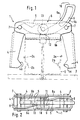
- a bracket denoted as a whole by 1 is used for connection of formwork panels arranged side by side in one plane on mutually facing edges, expediently on all Edges surrounding edge profiles 2, in the exemplary embodiment Have hollow profiles, these in Figures 1 and 3 Hollow sections and the formwork skins connected to them 3 are shown in broken lines.
- the bracket 1 has two against each other Longitudinal surfaces 2a facing away from one another Edge profiles 2 swiveling and compressing them Jaws 4 and an actuator to be described for this pivoting of the jaws 4.
- the two Clamping jaws 4 each have their own Clamping point 4a opposite end at an angle, in Embodiment an approximately right or slightly larger Angle, standing adjustment leg 5, the Adjustment leg 5 of the two jaws 4 towards each other are directed.
- Both jaws 4 are approximately in the corner area Transition to their adjustment legs 5 on a common one Carrier 6 pivotally mounted.
- the trained as joints Swivel bearing 7 can be clearly seen in all figures. In front in Fig.
- the ends of the adjustment legs 5 are connected to each other and with play swivel and point for this connection is a connecting element, in the exemplary embodiment a connecting bolt running transversely to the swivel plane 10 on who is the common point of attack for the wedge 9 forms.
- a connecting bolt running transversely to the swivel plane 10 on who is the common point of attack for the wedge 9 forms.
- abutment 12 for the formwork 3 facing mating wedge surface 9b of the wedge 9 which abutment 12 is the wedge 9 when driving or inserting supports so that its increasing width the Attack point, that is, the connecting bolt in the exemplary embodiment 10 displaced in the manner already described and emotional.
- the distance between the abutment 12 and the The point of attack of the wedge 9 is thus by this insertion the wedge 9 can be enlarged, that is, in a very simple manner is the displacement of the wedge 9 in a pivoting of the Adjustment leg 5 and thus the jaws 4 implemented.
- the abutment 12 has the advantage of always the same Support for the wedge 9 and wear to record due to the displacement of the wedge 9.
- Cross-section hollow or U-shaped carrier 6 also carries this abutment 12 for the wedge 9, which can be seen in FIGS and 3 can see well.
- the cross-section is approximately U-shaped Carrier 6 has on the side facing the formwork panel 3 a cross piece 6b and 6b connecting the two U-legs this crossbar 6b, which could itself form the abutment, carries this abutment 12 in the embodiment.
- the thickness this abutment 12 can be chosen so that the Wedge 9 finds favorable investment conditions.
- the wedge 9 in this way at the various points can apply and exert its wedge effect without one to cause misshapen bracket construction and to allow the Connecting bolt 10 in the manner already described near the Connection line of the two pivot bearings 7 arranged is, the wedge 9 is in the pivot plane about a perpendicular to imaginary axis lying at this pivoting plane, wherein the inside of this curvature as a wedge surface 9a on the as Connecting bolt 10 designed the point of attack Adjustment leg 5 rests and attacks.
- the wedge 9 is on the side facing away from the formlining 3 a wedge surface 9a formed as a narrow side Stop or projection 13, the displacement of the wedge 9th limited in the release movement so that the wedge 9 on the Clip 1 is also held in the release position as you would clearly recognizable in Fig.1.
- the release movement of the Wedge 9 by the one serving as the point of attack Cross bolt 10 cooperating projection 13 limited such that the wedge 9 both pivot bearings 7 and their Cross pins 8 also overlaps in the release position. So can also the narrow end of the wedge 9 already at the beginning of the clamping movement from the cross pin 8 of the corresponding pivot bearing 7 be performed.
- the length of the curved wedge 9 and the radius of curvature of the serving as a wedge surface 9a and the outside of the Wedge 9 bridged distances of the pivot bearings 7 are so chosen that the protruding part of the loosened wedge 9 with about its end face 16 arranged transversely to the wedge surfaces is arranged parallel to the formlining 3.
- bracket 1 there is an easy to use, out of a few Share existing bracket 1, which is very effective, too Can include hollow profiles as edge profiles 2 and a control allows whether the bracket is really closed or not, because this can be easily recognized by the position of the wedge 9 is. Because an increase in the clamping force, for example, by Extension of a lever arm or the like is not possible is, an overload of the edge webs 2 is also practical locked out.
- the bracket 1 is used to connect in one plane formwork panels arranged next to each other on their edge webs 2 and has two these bridges 2 squeezing Clamping jaws 4 facing away from their clamping point 4a Each ends at an angle to them Have adjustment legs 5.
- the adjustment legs 5 have in turn attack points for a wedge 9 Actuating or adjusting element, these points of attack on the two adjustment legs 5 expediently to one single point of attack for the wedge 9 are summarized.
- the wedge 9 can between this point of attack and Edge webs 2 expediently opposite one there on one slide along abutment 12 belonging to bracket 1 and thereby the point of attack and accordingly the adjustment leg 5 move away from the formlining 3 and thereby the jaws 4 conclude.
- a curved wedge is provided, which in the closing plane of the jaws 4 is movable.
Landscapes
- Engineering & Computer Science (AREA)
- Architecture (AREA)
- Mechanical Engineering (AREA)
- Civil Engineering (AREA)
- Structural Engineering (AREA)
- Clamps And Clips (AREA)
- Forms Removed On Construction Sites Or Auxiliary Members Thereof (AREA)
- Connection Of Plates (AREA)
- Joining Of Building Structures In Genera (AREA)
- Mutual Connection Of Rods And Tubes (AREA)
- Cable Accessories (AREA)
- Shielding Devices Or Components To Electric Or Magnetic Fields (AREA)
- Control Of Driving Devices And Active Controlling Of Vehicle (AREA)
- Casting Devices For Molds (AREA)
- Molds, Cores, And Manufacturing Methods Thereof (AREA)
- Automotive Seat Belt Assembly (AREA)
- Basic Packing Technique (AREA)
Description
- Fig. 1
- eine Draufsicht einer erfindungsgemäßen Klammer in geöffneter Position, jedoch vorbereitet zum Verspannen zweier aneinanderliegender, einen Hohlquerschnitt aufweisender Randprofile zweier in einer gemeinsamen Ebene liegender Schaltafeln, die nur teilweise und strichpunktiert angedeutet sind,
- Fig. 2
- eine Rückansicht der Klammer gemäß Fig.1 in noch geöffneter Position,
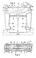
- Fig. 3
- eine der Fig. 1 entsprechende Darstellung der Klammer nach dem Schließen und Verspannen sowie
- Fig. 4
- eine Rückansicht der geschlossenen Klammer gemäß Fig. 3.
Claims (15)
- Klammer (1) zum Verbinden von in einer Ebene nebeneinander angeordneten Schaltafeln, die an wenigstens zwei einander zugewandten Rändern, insbesondere an allen Rändern umlaufende Randstege oder Randprofile (2), insbesondere Hohlprofile, haben, mit zwei gegen die voneinander abgewandten Längsflächen (2a) der aneinanderliegenden Randprofile (2) schwenkbaren und diese zusammendrückenden Spannbacken (4) und mit einem Betätigungselement für die Verschwenkung dieser Spannbacken (4), wobei die beiden Spannbacken (4) jeweils an ihrem von ihrer Klemmstelle (4a) abgewandten Ende einen im Winkel zu ihnen stehenden Verstellschenkel (5) aufweisen, diese Verstellschenkel (5) der beiden Spannbacken (4) aufeinander zu gerichtet sind, beide Spannbacken (4) etwa im Eckbereich ihrer beiden Schenkel an einem Träger (6) schwenkbar gelagert sind und wobei das Verstellelement einerseits mit Abstand zu der Schwenklagerung (7) an beiden Verstellschenkeln (5) und andererseits an einem Widerlager (12) angreift und die Angriffsstellen mit den Verstellschenkeln (5) zum Schließen der Klammer (1) von der Schalhaut (3) wegbewegbar sind, dadurch gekennzeichnet, daß das Verstellelement ein in Gebrauchsstellung zwischen den Angriffsstellen der Verstellschenkel (5) und den Randprofilen (2) angeordneter, längsverstellbarer Keil (9) ist, daß der Keil (9) mit seiner der Schalhaut (3) abgewandten Keilfläche (9a) an den Angriffsstellen der Verstellschenkel (5) angreift, daß der Keil (9) mit seiner der Schalhaut (3) zugewandten, seiner Keilfläche (9a) gegenüberliegenden Gegenkeilfläche (9b) an den Schwenklagerungen (7) beziehungsweise den diese bildenden Querstiften (8) der Spannbacken (4) als Führung oder Abstützung und an dem Widerlager (12) verschiebbar anliegt, daß der Keil (9) bei seiner Längsverstellung mit der Keilschräge entsprechend zunehmender Breite zum Schließen der Klammer (1) dient, daß die Angriffsstellen für den Keil (9) an den den Schwenklagerungen (7) der beiden Spannbacken (4) abgewandten Enden der Verstellschenkel (5) angeordnet und an übereinstimmender Stelle eine gemeinsame Angriffsstelle bildend vorgesehen sind und daß die Enden der Verstellschenkel (5) miteinander mit Spiel schwenkbar verbunden sind und das Verbindungselement die gemeinsame Angriffsstelle für den Keil (9) bildet.
- Klammer nach Anspruch 1, dadurch gekennzeichnet, daß ein quer zur Schwenkebene verlaufender Verbindungsbolzen (10) als Verbindungselement der Enden der Verstellschenkel (5) vorgesehen ist.
- Klammer nach Anspruch 1 oder 2, dadurch gekennzeichnet, daß sich die Verstellschenkel (5) an ihren Enden überlappen und der Überlappungsbereich von dem Verbindungselement oder Verbindungsbolzen (10) durchsetzt ist.
- Klammer nach einem der Ansprüche 1 bis 3, dadurch gekennzeichnet, daß die Angriffsstelle(n) in Lösestellung auf einer Verbindungslinie der beiden Schwenklagerungen (7) oder mit kleinem Abstand von dieser Verbindungslinie auf der der Schaltafel zugewandten Seite dieser Verbindungslinie und in Spannstellung auf der der Schalhaut (3) und der Schaltafel abgewandten Seite dieser Verbindungslinie der beiden Schwenklagerungen (7) angeordnet ist/sind.
- Klammer nach einem der Ansprüche 1 bis 4, dadurch gekennzeichnet, daß im Bereich der Angriffsstelle(n) des Keiles (9) an den Verstellschenkeln (5) mit Abstand zu diesen Angriffsstellen das Widerlager (12) für die der Schalhaut (3) zugewandte Gegenkeilfläche (9b) des Keiles (9) vorgesehen ist und der Abstand zwischen dem Widerlager (12) und der oder den Angriffsstellen des Keiles (9) durch das Einschieben des Keiles (9) vergrößerbar ist.
- Klammer nach einem der Ansprüche 1 bis 5, dadurch gekennzeichnet, daß der die Schwenklagerungen (7) der Spannbacken (4) aufweisende, im Querschnitt hohle oder U-förmige Träger (6) das Widerlager (12) für den Keil (9) trägt.
- Klammer nach einem der Ansprüche 1 bis 6, dadurch gekennzeichnet, daß der im Querschnitt etwa U-förmige Träger (6) auf der der Schalhaut (2) zugewandten Seite einen seine beiden U-Schenkel (6a) verbindenden Quersteg (6b) hat und dieser Quersteg (6b) das Widerlager (12) bildet oder trägt.
- Klammer nach einem der Ansprüche 1 bis 7, dadurch gekennzeichnet, daß der Keil (9) in der Schwenkebene der Spannbacken (4) und der Verstellschenkel (5) verschiebbar oder verstellbar ist und seine Keilfläche (9a) und die dieser gegenüberliegende Gegenkeilfläche (9b) rechtwinklig dazu angeordnet sind.
- Klammer nach einem der Ansprüche 1 bis 8, dadurch gekennzeichnet, daß der Keil (9) in der Schwenkebene um eine senkrecht zu dieser Schwenkebene liegende, gedachte Achse gekrümmt ist, wobei die Innenseite der Krümmung als Keilfläche (9a) an der oder den Angriffsstellen der Verstellschenkel (5) anliegt.
- Klammer nach Anspruch 9, dadurch gekennzeichnet, daß die die Gegenkeilfläche (9b) bildende Außenseite der Krümmung des Keiles (9) an den Schwenklagerungen (7) und/ dem Widerlager (12) angreift.
- Klammer nach Anspruch 9 oder 10, dadurch gekennzeichnet, daß die die Gegenkeilfläche (9b) bildende Außenkrümmung des Keiles (9) stetig durchgehend bogenförmig, insbesondere kreisbogenförmig ist.
- Klammer nach einem der Ansprüche 1 bis 11, dadurch gekennzeichnet, daß der Keil (9) auf der der Schalhaut (3) abgewandten Seite an seiner insbesondere als Schmalseite ausgebildeten Keilfläche (9a) einen Anschlag oder Vorsprung (13) hat, der ein Verschieben des Keiles (9) bei der Lösebewegung derart begrenzt, daß der Keil (9) an der Klammer (1) auch in Löseposition gehalten ist.
- Klammer nach einem der Ansprüche 1 bis 12, dadurch gekennzeichnet, daß die Lösebewegung des Keiles (9) durch den mit dem als Angriffsstelle dienenden Querbolzen (10) zusammenwirkenden Vorsprung (13) derart begrenzt ist, daß der Keil (9) beide Schwenklagerungen (7) auch in Lösestellung übergreift.
- Klammer nach einem der Ansprüche 1 bis 13, dadurch gekennzeichnet, daß die Verbreiterung des Keiles (9) in seiner Erstreckungsrichtung, also der Keilwinkel, unter einem solchen Winkel steht, daß in Klemmstellung Selbsthemmung gegeben ist, und daß beide Enden des Keiles insbesonders etwa in einer parallel zur Schalhaut (3) liegenden Ebene angeordnet sind.
- Klammer nach einem der Ansprüche 1 bis 14, dadurch gekennzeichnet, daß die Länge des gekrümmten Keiles (9) und der Krümmungsradius der als Keilfläche (9a) dienenden Außenseite sowie die dabei von dem Keil (9) überbrückten Abstände der Schwenklagerungen (7) so gewählt sind, daß der überstehende Teil des gelösten Keiles (9) mit seiner quer zu der Keilfläche (9a) und der Gegenkeilfläche (9b) angeordneten Stirnseite (16) etwa parallel zur Schalhaut (3) angeordnet ist.
Priority Applications (1)
| Application Number | Priority Date | Filing Date | Title |
|---|---|---|---|
| SI9430185T SI0674068T1 (en) | 1994-01-22 | 1994-12-24 | Clamps for connecting form elements clamping arms engaging the border sections |
Applications Claiming Priority (2)
| Application Number | Priority Date | Filing Date | Title |
|---|---|---|---|
| DE4401794 | 1994-01-22 | ||
| DE4401794A DE4401794C2 (de) | 1994-01-22 | 1994-01-22 | Klammer zum Verbinden von Schaltafeln mit deren Randprofile zusammendrückenden Spannbacken |
Publications (2)
| Publication Number | Publication Date |
|---|---|
| EP0674068A1 EP0674068A1 (de) | 1995-09-27 |
| EP0674068B1 true EP0674068B1 (de) | 1998-06-24 |
Family
ID=6508440
Family Applications (1)
| Application Number | Title | Priority Date | Filing Date |
|---|---|---|---|
| EP94120651A Expired - Lifetime EP0674068B1 (de) | 1994-01-22 | 1994-12-24 | Klammer zum Verbinden von Schaltafeln mit deren Randprofile zusammendrückenden Spannbacken |
Country Status (26)
| Country | Link |
|---|---|
| US (1) | US5570500A (de) |
| EP (1) | EP0674068B1 (de) |
| KR (1) | KR100393375B1 (de) |
| CN (1) | CN1080810C (de) |
| AT (1) | ATE167719T1 (de) |
| AU (1) | AU682909B2 (de) |
| BR (1) | BR9500264A (de) |
| CA (1) | CA2140710C (de) |
| CZ (1) | CZ287778B6 (de) |
| DE (2) | DE4401794C2 (de) |
| DK (1) | DK0674068T3 (de) |
| DZ (1) | DZ1845A1 (de) |
| EE (1) | EE03244B1 (de) |
| ES (1) | ES2118306T3 (de) |
| HK (1) | HK1007383A1 (de) |
| IL (1) | IL112411A (de) |
| LV (1) | LV11357B (de) |
| MA (1) | MA23428A1 (de) |
| MY (1) | MY121945A (de) |
| PL (1) | PL176505B1 (de) |
| RU (1) | RU2125636C1 (de) |
| SI (1) | SI0674068T1 (de) |
| SK (1) | SK284559B6 (de) |
| TN (1) | TNSN95002A1 (de) |
| TR (1) | TR28908A (de) |
| ZA (1) | ZA9410257B (de) |
Families Citing this family (37)
| Publication number | Priority date | Publication date | Assignee | Title |
|---|---|---|---|---|
| FR2721087B1 (fr) * | 1994-06-09 | 1996-07-19 | Schneider Electric Sa | Dispositif de support pour goulotte. |
| DE19507384B4 (de) * | 1995-03-03 | 2011-08-11 | Friedr. Ischebeck GmbH, 58256 | Rahmenschalungs-Elemente |
| US6132368A (en) | 1996-12-12 | 2000-10-17 | Intuitive Surgical, Inc. | Multi-component telepresence system and method |
| US8182469B2 (en) * | 1997-11-21 | 2012-05-22 | Intuitive Surgical Operations, Inc. | Surgical accessory clamp and method |
| US8529582B2 (en) | 1996-12-12 | 2013-09-10 | Intuitive Surgical Operations, Inc. | Instrument interface of a robotic surgical system |
| US7727244B2 (en) | 1997-11-21 | 2010-06-01 | Intuitive Surgical Operation, Inc. | Sterile surgical drape |
| US8206406B2 (en) | 1996-12-12 | 2012-06-26 | Intuitive Surgical Operations, Inc. | Disposable sterile surgical adaptor |
| US6331181B1 (en) | 1998-12-08 | 2001-12-18 | Intuitive Surgical, Inc. | Surgical robotic tools, data architecture, and use |
| BE1012700A3 (nl) * | 1999-06-02 | 2001-02-06 | Cometal Nv | Klem voor een betonbekisting. |
| US6499260B2 (en) | 2000-02-23 | 2002-12-31 | Amtech Corporation | Portable greenhouse structure and method and apparatus for assembling same |
| US6966550B2 (en) | 2002-10-18 | 2005-11-22 | Worktools, Inc. | One hand actuated “C” clamp |
| US6681778B1 (en) * | 2002-11-18 | 2004-01-27 | Linshell Holdings Limited | Hair clip |
| GB2385266B (en) * | 2002-11-18 | 2004-01-07 | Linshell Holdings Ltd | A hair clip |
| DE10331359B4 (de) | 2003-07-11 | 2010-07-15 | Peri Gmbh | Spannschlossvorrichtung mit schräg geführtem Keil |
| ES2292272B1 (es) * | 2004-06-24 | 2008-10-01 | Transformados Muper, S.L. | Mecanismo para la sujecion de paneles de muro adyacentes. |
| CN100366849C (zh) * | 2005-02-04 | 2008-02-06 | 刘国恩 | 模板拼装连接卡具 |
| ES2249188B1 (es) | 2005-04-11 | 2006-12-01 | Ingenieria De Encofrados Y Servicios, S.L. | Mordaza para sujecion de paneles de encofrado. |
| US20070175368A1 (en) * | 2006-01-31 | 2007-08-02 | Yoder Ervin E | Leaf table having lockable slide rails |
| ES2303434B1 (es) * | 2006-03-28 | 2009-06-03 | Inveral, S.A. | Procedimiento para la fabricacion de un dispositivo de union para paneles encofrados y dispositivo obtenido segun dicho procedimiento. |
| US8573576B2 (en) * | 2009-06-26 | 2013-11-05 | Intuitive Research And Technology Corporation | Clamp for single-handed operation |
| MD4161C1 (ro) * | 2011-01-10 | 2012-10-31 | Николае Попеску | Procedeu de executare a construcţiei monolite, a complexului de construcţii monolite şi echipament tehnologic pentru realizarea acestuia |
| US8720958B2 (en) | 2011-03-15 | 2014-05-13 | Carlson Pet Products, Inc. | Barrier with panels sliding parallel |
| US8627603B2 (en) | 2011-03-15 | 2014-01-14 | Carlson Pet Products, Inc. | Barrier with panels sliding parallel |
| US9260910B1 (en) | 2012-06-13 | 2016-02-16 | Carlson Pet Products, Inc. | Free standing sliding panel footed barrier |
| CN106102642B (zh) * | 2014-03-17 | 2020-03-31 | 直观外科手术操作公司 | 外科手术套管安装件及相关的系统和方法 |
| CN104295099B (zh) * | 2014-09-09 | 2016-06-08 | 广州市艺达机械有限公司 | 模板拼装用连接卡具 |
| CN104475968B (zh) * | 2014-11-21 | 2016-06-08 | 兰州爱赛特机电科技有限公司 | 摩擦焊接用顶锻自锁式钢爪液压夹具 |
| US12195961B2 (en) | 2016-06-24 | 2025-01-14 | Apache Industrial Services, Inc. | Formwork system |
| US10472823B2 (en) * | 2016-06-24 | 2019-11-12 | Apache Industrial Services, Inc. | Formwork system |
| US11624196B2 (en) | 2016-06-24 | 2023-04-11 | Apache Industrial Services, Inc | Connector end fitting for an integrated construction system |
| US11976483B2 (en) | 2016-06-24 | 2024-05-07 | Apache Industrial Services, Inc | Modular posts of an integrated construction system |
| US11306492B2 (en) | 2016-06-24 | 2022-04-19 | Apache Industrial Services, Inc | Load bearing components and safety deck of an integrated construction system |
| CN106930415B (zh) * | 2017-03-07 | 2022-04-12 | 西安建筑科技大学 | 一种适用于建筑领域的自锁性锁具及应用 |
| CN107237798B (zh) * | 2017-07-28 | 2023-03-31 | 深圳市光祥科技股份有限公司 | 连接结构及显示屏 |
| CN107355074A (zh) * | 2017-08-09 | 2017-11-17 | 中国水利水电第十四工程局有限公司 | 一种用于模板工程的夹爪式支撑 |
| KR102048985B1 (ko) * | 2018-08-31 | 2019-11-27 | 주식회사 연우건재 | 인테리어 보드의 높낮이 맞춤 시공 기구 |
| DE112021007626T5 (de) * | 2021-05-07 | 2024-02-29 | Fuji Corporation | Übertragungsvorrichtung und Arbeitsvorrichtung |
Family Cites Families (14)
| Publication number | Priority date | Publication date | Assignee | Title |
|---|---|---|---|---|
| US1376614A (en) * | 1919-08-14 | 1921-05-03 | Hydraulic Pressed Steel Co | Clamp for concrete-forms |
| DE809045C (de) * | 1949-08-03 | 1951-07-23 | Walter Lauterjung | Haarschere |
| US4188017A (en) * | 1978-10-10 | 1980-02-12 | Gerhard Dingler | Tensioning device for frame pieces |
| DE8009045U1 (de) * | 1980-04-01 | 1980-10-09 | Oesterreichische Doka Schalungs- Und Geruestungstechnik Gmbh, Amstetten (Oesterreich) | Spannvorrichtung fuer rahmenschalungen |
| IT1172928B (it) * | 1983-12-28 | 1987-06-18 | Alpi Casseforme Spa | Chiavetta di allineamento e di serraggio |
| DE3724872C1 (de) * | 1987-07-28 | 1988-10-27 | Maier Josef | Befestigungsklammer zum Verbinden der Randstege von Schaltafeln |
| DE3734390C2 (de) * | 1987-10-10 | 1993-10-28 | Gerhard Dingler | Verbund für Fertigschalungen |
| DE3823763A1 (de) * | 1988-07-13 | 1990-01-18 | Steidle Gmbh & Co Emil | Klammer zur verbindung der profilrahmen von rahmentafelschalungen |
| DE8814208U1 (de) * | 1988-11-12 | 1989-01-05 | Maier, Josef, 7619 Steinach | Klammer zum Verbinden von Schaltafeln |
| DE3941935C2 (de) * | 1989-12-19 | 1999-04-15 | Oesterr Doka Schalung | Spannschloß |
| DE4007950C2 (de) * | 1990-03-13 | 1994-04-14 | Thyssen Huennebeck Gmbh | Vorrichtung zum Verbinden und Verspannen von Schaltafeln |
| ATE131898T1 (de) * | 1991-10-15 | 1996-01-15 | Felix Jose Luis Ubinana | Vorrichtung zur schnellverbindung von schalungspanelen für betonkonstruktionen |
| DE4205990C1 (en) * | 1992-02-27 | 1993-02-11 | Paschal-Werk G. Maier Gmbh, 7619 Steinach, De | Clamp used in concrete shuttering - is tightened by wedge and has projections engaging groves in frame members |
| AU664914B2 (en) * | 1992-10-26 | 1995-12-07 | Paschal-Werk G. Maier Gmbh | A clamp for connecting the sections at the edges of formwork panels |
-
1994
- 1994-01-22 DE DE4401794A patent/DE4401794C2/de not_active Expired - Lifetime
- 1994-12-20 AU AU81574/94A patent/AU682909B2/en not_active Ceased
- 1994-12-22 ZA ZA9410257A patent/ZA9410257B/xx unknown
- 1994-12-24 EP EP94120651A patent/EP0674068B1/de not_active Expired - Lifetime
- 1994-12-24 AT AT94120651T patent/ATE167719T1/de active
- 1994-12-24 DE DE59406320T patent/DE59406320D1/de not_active Expired - Lifetime
- 1994-12-24 SI SI9430185T patent/SI0674068T1/xx not_active IP Right Cessation
- 1994-12-24 DK DK94120651T patent/DK0674068T3/da active
- 1994-12-24 ES ES94120651T patent/ES2118306T3/es not_active Expired - Lifetime
-
1995
- 1995-01-10 MA MA23755A patent/MA23428A1/fr unknown
- 1995-01-12 TR TR00030/95A patent/TR28908A/xx unknown
- 1995-01-13 MY MYPI95000092A patent/MY121945A/en unknown
- 1995-01-16 CZ CZ1995104A patent/CZ287778B6/cs not_active IP Right Cessation
- 1995-01-17 CN CN95101698A patent/CN1080810C/zh not_active Expired - Lifetime
- 1995-01-18 PL PL95306879A patent/PL176505B1/pl unknown
- 1995-01-18 SK SK66-95A patent/SK284559B6/sk not_active IP Right Cessation
- 1995-01-18 DZ DZ950004A patent/DZ1845A1/fr active
- 1995-01-19 BR BR9500264A patent/BR9500264A/pt not_active IP Right Cessation
- 1995-01-20 LV LVP-95-17A patent/LV11357B/lv unknown
- 1995-01-20 US US08/375,865 patent/US5570500A/en not_active Expired - Lifetime
- 1995-01-20 CA CA002140710A patent/CA2140710C/en not_active Expired - Lifetime
- 1995-01-20 TN TNTNSN95002A patent/TNSN95002A1/fr unknown
- 1995-01-20 RU RU95101034A patent/RU2125636C1/ru active
- 1995-01-20 EE EE9500011A patent/EE03244B1/xx not_active IP Right Cessation
- 1995-01-22 IL IL112411A patent/IL112411A/en not_active IP Right Cessation
- 1995-01-23 KR KR1019950001081A patent/KR100393375B1/ko not_active Expired - Fee Related
-
1998
- 1998-06-24 HK HK98106438A patent/HK1007383A1/xx not_active IP Right Cessation
Also Published As
Similar Documents
| Publication | Publication Date | Title |
|---|---|---|
| DE4401794C2 (de) | Klammer zum Verbinden von Schaltafeln mit deren Randprofile zusammendrückenden Spannbacken | |
| EP3818225B1 (de) | Möbelbeschlag | |
| EP0369197B1 (de) | Klammer zum Verbinden von Schaltafeln | |
| EP0914530B1 (de) | Klammer mit spannbacken und einem diese verbindenden träger | |
| EP0594962B1 (de) | Klammer zum Verbinden der Randprofile von Schaltafeln | |
| CH695482A5 (de) | Montagegerät zum Setzen von Schrauben beim Verbinden von einander an ihren Enden überlappenden Holzbalken. | |
| DE2163994A1 (de) | Klemmverbindung | |
| AT519903A1 (de) | Schiene zur Führung eines Schlittens einer Möbeltüre | |
| DE4236070C2 (de) | Klammer zum Verbinden der Randprofile von Schaltafeln | |
| EP2345786A2 (de) | Türband für Aluminiumtüren | |
| DE3308219C2 (de) | Maschine zum Profilieren von Blechen für die Herstellung von Falzen | |
| DE3941935C2 (de) | Spannschloß | |
| EP1506741A1 (de) | Modular koppelbare Geräteanordnung | |
| EP0539672A1 (de) | Beschlag zur Befestigung in einer beidseitig hinterschnittenen Profilnut | |
| DE2951588C2 (de) | Vorrichtung zum Befestigen von Scharnierlappen an Zargen für Türen | |
| EP0563121B1 (de) | Verbindungsvorrichtung für wenigstens zwei aneinanderliegende balken | |
| DE112023004887T5 (de) | Klemme | |
| DE9315482U1 (de) | Zangenartiges Werkzeug zum formschlüssigen Verbinden von Blechteilen | |
| DE19955289C2 (de) | Buchsenziehvorrichtung | |
| DE1452678A1 (de) | Vorrichtung zum Kaltstauchen von Metallbandagen | |
| DE4103776C1 (en) | Shuttering panels for building construction - have clamps including cams with rotation axis at right angles to plane of panel | |
| DE3837444C1 (en) | Device for mutual clamping of two objects | |
| EP3359763A1 (de) | Scharnier für eine faltklappe | |
| DE9401039U1 (de) | Klammer zum Verbinden von Schaltafeln mit deren Randporfile zusammendrückenden Spannbacken | |
| DE19500128A1 (de) | Zwinge für das Bauwesen |
Legal Events
| Date | Code | Title | Description |
|---|---|---|---|
| PUAI | Public reference made under article 153(3) epc to a published international application that has entered the european phase |
Free format text: ORIGINAL CODE: 0009012 |
|
| AK | Designated contracting states |
Kind code of ref document: A1 Designated state(s): AT BE CH DE DK ES FR GB GR IE IT LI LU MC NL PT SE |
|
| RAX | Requested extension states of the european patent have changed |
Free format text: LT PAYMENT 941224;SI PAYMENT 941224 |
|
| ITCL | It: translation for ep claims filed |
Representative=s name: ZINI MARANESI |
|
| 17P | Request for examination filed |
Effective date: 19950829 |
|
| EL | Fr: translation of claims filed | ||
| 17Q | First examination report despatched |
Effective date: 19961021 |
|
| GRAG | Despatch of communication of intention to grant |
Free format text: ORIGINAL CODE: EPIDOS AGRA |
|
| GRAG | Despatch of communication of intention to grant |
Free format text: ORIGINAL CODE: EPIDOS AGRA |
|
| GRAH | Despatch of communication of intention to grant a patent |
Free format text: ORIGINAL CODE: EPIDOS IGRA |
|
| GRAH | Despatch of communication of intention to grant a patent |
Free format text: ORIGINAL CODE: EPIDOS IGRA |
|
| GRAA | (expected) grant |
Free format text: ORIGINAL CODE: 0009210 |
|
| AK | Designated contracting states |
Kind code of ref document: B1 Designated state(s): AT BE CH DE DK ES FR GB GR IE IT LI LU MC NL PT SE |
|
| AX | Request for extension of the european patent |
Free format text: LT PAYMENT 941224;SI PAYMENT 941224 |
|
| PG25 | Lapsed in a contracting state [announced via postgrant information from national office to epo] |
Ref country code: GR Free format text: LAPSE BECAUSE OF NON-PAYMENT OF DUE FEES Effective date: 19980624 |
|
| REF | Corresponds to: |
Ref document number: 167719 Country of ref document: AT Date of ref document: 19980715 Kind code of ref document: T |
|
| REG | Reference to a national code |
Ref country code: CH Ref legal event code: NV Representative=s name: HANS RUDOLF GACHNANG PATENTANWALT Ref country code: CH Ref legal event code: EP |
|
| GBT | Gb: translation of ep patent filed (gb section 77(6)(a)/1977) |
Effective date: 19980624 |
|
| REF | Corresponds to: |
Ref document number: 59406320 Country of ref document: DE Date of ref document: 19980730 |
|
| ITF | It: translation for a ep patent filed | ||
| REG | Reference to a national code |
Ref country code: ES Ref legal event code: FG2A Ref document number: 2118306 Country of ref document: ES Kind code of ref document: T3 |
|
| REG | Reference to a national code |
Ref country code: IE Ref legal event code: FG4D Free format text: GERMAN |
|
| PG25 | Lapsed in a contracting state [announced via postgrant information from national office to epo] |
Ref country code: SE Free format text: LAPSE BECAUSE OF FAILURE TO SUBMIT A TRANSLATION OF THE DESCRIPTION OR TO PAY THE FEE WITHIN THE PRESCRIBED TIME-LIMIT Effective date: 19980924 |
|
| ET | Fr: translation filed | ||
| REG | Reference to a national code |
Ref country code: PT Ref legal event code: SC4A Free format text: AVAILABILITY OF NATIONAL TRANSLATION Effective date: 19980820 |
|
| PG25 | Lapsed in a contracting state [announced via postgrant information from national office to epo] |
Ref country code: LU Free format text: LAPSE BECAUSE OF NON-PAYMENT OF DUE FEES Effective date: 19981224 |
|
| REG | Reference to a national code |
Ref country code: DK Ref legal event code: T3 |
|
| PLBE | No opposition filed within time limit |
Free format text: ORIGINAL CODE: 0009261 |
|
| STAA | Information on the status of an ep patent application or granted ep patent |
Free format text: STATUS: NO OPPOSITION FILED WITHIN TIME LIMIT |
|
| 26N | No opposition filed | ||
| PG25 | Lapsed in a contracting state [announced via postgrant information from national office to epo] |
Ref country code: MC Free format text: LAPSE BECAUSE OF NON-PAYMENT OF DUE FEES Effective date: 19990630 |
|
| REG | Reference to a national code |
Ref country code: GB Ref legal event code: IF02 |
|
| REG | Reference to a national code |
Ref country code: SI Ref legal event code: IF |
|
| PGFP | Annual fee paid to national office [announced via postgrant information from national office to epo] |
Ref country code: IE Payment date: 20101210 Year of fee payment: 17 |
|
| PGFP | Annual fee paid to national office [announced via postgrant information from national office to epo] |
Ref country code: PT Payment date: 20101029 Year of fee payment: 17 |
|
| REG | Reference to a national code |
Ref country code: PT Ref legal event code: MM4A Free format text: LAPSE DUE TO NON-PAYMENT OF FEES Effective date: 20120625 |
|
| LTLA | Lt: lapse of european patent or patent extension |
Effective date: 20111224 |
|
| PG25 | Lapsed in a contracting state [announced via postgrant information from national office to epo] |
Ref country code: PT Free format text: LAPSE BECAUSE OF NON-PAYMENT OF DUE FEES Effective date: 20120625 |
|
| REG | Reference to a national code |
Ref country code: IE Ref legal event code: MM4A |
|
| PG25 | Lapsed in a contracting state [announced via postgrant information from national office to epo] |
Ref country code: IE Free format text: LAPSE BECAUSE OF NON-PAYMENT OF DUE FEES Effective date: 20111224 |
|
| PGFP | Annual fee paid to national office [announced via postgrant information from national office to epo] |
Ref country code: CH Payment date: 20131216 Year of fee payment: 20 Ref country code: DK Payment date: 20131219 Year of fee payment: 20 Ref country code: GB Payment date: 20131218 Year of fee payment: 20 Ref country code: AT Payment date: 20131213 Year of fee payment: 20 |
|
| PGFP | Annual fee paid to national office [announced via postgrant information from national office to epo] |
Ref country code: BE Payment date: 20131122 Year of fee payment: 20 Ref country code: ES Payment date: 20131210 Year of fee payment: 20 Ref country code: IT Payment date: 20131223 Year of fee payment: 20 Ref country code: NL Payment date: 20131216 Year of fee payment: 20 |
|
| REG | Reference to a national code |
Ref country code: CH Ref legal event code: NV Representative=s name: GACHNANG AG PATENTANWAELTE, CH |
|
| PGFP | Annual fee paid to national office [announced via postgrant information from national office to epo] |
Ref country code: DE Payment date: 20131230 Year of fee payment: 20 |
|
| PGFP | Annual fee paid to national office [announced via postgrant information from national office to epo] |
Ref country code: FR Payment date: 20131212 Year of fee payment: 20 |
|
| REG | Reference to a national code |
Ref country code: DE Ref legal event code: R071 Ref document number: 59406320 Country of ref document: DE |
|
| REG | Reference to a national code |
Ref country code: DE Ref legal event code: R071 Ref document number: 59406320 Country of ref document: DE |
|
| REG | Reference to a national code |
Ref country code: NL Ref legal event code: V4 Effective date: 20141224 Ref country code: CH Ref legal event code: PL |
|
| REG | Reference to a national code |
Ref country code: DK Ref legal event code: EUP Effective date: 20141224 |
|
| REG | Reference to a national code |
Ref country code: GB Ref legal event code: PE20 Expiry date: 20141223 |
|
| PG25 | Lapsed in a contracting state [announced via postgrant information from national office to epo] |
Ref country code: GB Free format text: LAPSE BECAUSE OF EXPIRATION OF PROTECTION Effective date: 20141223 |
|
| REG | Reference to a national code |
Ref country code: AT Ref legal event code: MK07 Ref document number: 167719 Country of ref document: AT Kind code of ref document: T Effective date: 20141224 |
|
| REG | Reference to a national code |
Ref country code: ES Ref legal event code: FD2A Effective date: 20150303 |
|
| PG25 | Lapsed in a contracting state [announced via postgrant information from national office to epo] |
Ref country code: ES Free format text: LAPSE BECAUSE OF EXPIRATION OF PROTECTION Effective date: 20141225 |