EP0674077A1 - Porte - Google Patents
Porte Download PDFInfo
- Publication number
- EP0674077A1 EP0674077A1 EP95810189A EP95810189A EP0674077A1 EP 0674077 A1 EP0674077 A1 EP 0674077A1 EP 95810189 A EP95810189 A EP 95810189A EP 95810189 A EP95810189 A EP 95810189A EP 0674077 A1 EP0674077 A1 EP 0674077A1
- Authority
- EP
- European Patent Office
- Prior art keywords
- door
- door leaf
- pivot shaft
- groove
- pin
- Prior art date
- Legal status (The legal status is an assumption and is not a legal conclusion. Google has not performed a legal analysis and makes no representation as to the accuracy of the status listed.)
- Granted
Links
- 230000008719 thickening Effects 0.000 claims description 6
- 239000000463 material Substances 0.000 description 3
- 238000013459 approach Methods 0.000 description 1
- 239000002184 metal Substances 0.000 description 1
Images

Classifications
-
- E—FIXED CONSTRUCTIONS
- E05—LOCKS; KEYS; WINDOW OR DOOR FITTINGS; SAFES
- E05B—LOCKS; ACCESSORIES THEREFOR; HANDCUFFS
- E05B63/00—Locks or fastenings with special structural characteristics
- E05B63/14—Arrangement of several locks or locks with several bolts, e.g. arranged one behind the other
-
- E—FIXED CONSTRUCTIONS
- E05—LOCKS; KEYS; WINDOW OR DOOR FITTINGS; SAFES
- E05D—HINGES OR SUSPENSION DEVICES FOR DOORS, WINDOWS OR WINGS
- E05D15/00—Suspension arrangements for wings
- E05D15/06—Suspension arrangements for wings for wings sliding horizontally more or less in their own plane
- E05D15/0621—Details, e.g. suspension or supporting guides
- E05D15/0626—Details, e.g. suspension or supporting guides for wings suspended at the top
- E05D15/063—Details, e.g. suspension or supporting guides for wings suspended at the top on wheels with fixed axis
-
- E—FIXED CONSTRUCTIONS
- E05—LOCKS; KEYS; WINDOW OR DOOR FITTINGS; SAFES
- E05D—HINGES OR SUSPENSION DEVICES FOR DOORS, WINDOWS OR WINGS
- E05D15/00—Suspension arrangements for wings
- E05D15/28—Suspension arrangements for wings supported on arms movable in horizontal plane
- E05D15/30—Suspension arrangements for wings supported on arms movable in horizontal plane with pivoted arms and sliding guides
-
- E—FIXED CONSTRUCTIONS
- E05—LOCKS; KEYS; WINDOW OR DOOR FITTINGS; SAFES
- E05Y—INDEXING SCHEME ASSOCIATED WITH SUBCLASSES E05D AND E05F, RELATING TO CONSTRUCTION ELEMENTS, ELECTRIC CONTROL, POWER SUPPLY, POWER SIGNAL OR TRANSMISSION, USER INTERFACES, MOUNTING OR COUPLING, DETAILS, ACCESSORIES, AUXILIARY OPERATIONS NOT OTHERWISE PROVIDED FOR, APPLICATION THEREOF
- E05Y2900/00—Application of doors, windows, wings or fittings thereof
- E05Y2900/10—Application of doors, windows, wings or fittings thereof for buildings or parts thereof
- E05Y2900/13—Type of wing
- E05Y2900/132—Doors
Definitions
- the present invention relates to a door with a pivot shaft for a door leaf, with arms which are connected at one end to the pivot shaft and at the other end to the door leaf, one of these arms being in the upper region and the other arm in the lower region of the pivot shaft, and with one Guide device for the door leaf.
- a door of this type is already known.
- the wing of this door is designed so that it practically completely fills the opening in a door frame.
- the swivel shaft and the swivel arms are located on one of the large sides of the door leaf.
- the wing of this door can only be swiveled out of its closed position in one direction. This has the disadvantage that you have to move backwards when opening the door if you want to open the door from the side in which the door swings out when opening.
- the object of the present invention is to provide a door which does not have the mentioned disadvantage or further disadvantages of the prior art.
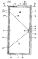
- FIG. 1 shows the present door in a front view.
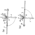
- FIG. 2 shows the door according to FIG. 1 in a view from above and partly in a horizontal section X-X.
- 3 shows a side view of the upper section of the door according to FIG. 1.
- This door comprises a frame 1 and a leaf 2.
- the door leaf 2 has a conventional square shape, in which the dimension of the horizontally lying narrow sides thereof is smaller than the dimension of the vertical narrow side of the door leaf 2.
- the door frame 1 is inserted in a building or wall opening 4 and firmly connected to it in a manner known per se.
- the base body 3 of the door frame 1 comprises a vertically extending side leg 12, the ends of which are fastened in the space opening 4.
- This leg 12 is advantageously designed as a hollow square profile. This profile can be rectangular or square. In the case shown, the cross section of the hollow profile 12 is square.
- a practically horizontal-lying support rail 13 is rigidly connected at one end to the upper end of the frame leg 12.
- the other end of the mounting rail 13 is embedded in the material of the space opening 4.
- a practically horizontal bottom rail 8 is connected at one end to the lower end of the lateral frame leg 12.
- This floor rail 8 is advantageously embedded in the floor area of the room opening 4.
- This bottom rail 8 can be designed as a metal strip, the main surfaces of which run horizontally.
- the door leaf 2 can be designed as a single plate made of a suitable material.
- the door leaf 2 has a frame 25, the shape of which corresponds to the shape of the room opening 4 and which can be accommodated in this opening 4.
- This frame 25 is provided on both sides with a relatively thin plate 26 and 27 (Fig. 2). These plates 26 and 27 can extend over the entire surface of the casement 25. 1 and 3, only one of these plates 26 can be seen.
- the sash 25 has two vertical side pieces 31 and 32 and horizontal pieces 33 and 34.
- the door further comprises a pivot axis 5 which extends between the support rail 13 and the bottom rail 8.
- This pivot axis 5 is also located inside the room opening 4 and it is practically in the same plane as the door leaf 2.
- the pivot axis 5 lies between one of the vertical sides of the room opening 4 and the wall side facing this lying narrow side 31 of the door leaf 2.
- the pivot axis 5 is designed as a shaft which is mounted in the support rail 13 and in the bottom rail 8 freely rotatable or freely pivotable.
- the pivot shaft 5 is advantageously designed as a hollow square profile. This profile can be rectangular or square. In the case shown, the cross section of the hollow profile 5 is square.
- the pivot shaft 5 is located as close as possible to the above-mentioned side of the room opening 4 and as close as possible to the vertical narrow side 31 of the door leaf 2 so that the gaps between them are as small as possible.
- This column can be sealed or covered, for example by felt strips inserted into the column, by bristles extending transversely to these columns or the like.
- a bolt or fishing bolt 6 protruding from this shaft end part is inserted, which passes through a closure piece 43 in the shaft end part.
- the portion of the bolts 6 protruding from the pivot shaft 5 are rotatably supported in bores 7, one of which is embodied in the mounting rail 13 and one in the bottom rail 8, respectively.
- the pivot shaft 5 can also be mounted such that the bolts 6 are fastened in the inner surfaces of the space opening 4 and that the portions of the bolts 6 protruding from the inner wall of the space opening 4 in the End parts of the pivot shaft 5 are freely rotatable or freely pivotable.
- the door also has pivot arms 14 and 15.
- the first of these swivel arms 14 is in the region of the support rail 13 and the other of these swivel arms 15 is arranged in the region of the base rail 8.
- these arms 14 and 15 are as close as possible to the mounting rail 13 or to the bottom rail 8 and to the door leaf 2.
- the arms 14 and 15 are made as thin as possible so that the gap between the mounting rail 13 and the door leaf 2 and Gap between the bottom rail 8 and the door leaf 2 can be kept as small as possible.
- the respective arm 14 or 15 is assigned to the pivot shaft 5.
- the first end part of the pivot levers 14 and 15 is attached to the pivot shaft 5.
- the pivot arms 14 and 15 are pivotably mounted on such an axis 5.
- the swivel arms 14 and 15 can be swiveled to the two sides of the room or door opening 4.
- the other ends of these arms 14 and 15 are hinged to the door leaf 2.
- the length of the arms 14 and 15 corresponds to approximately one third of the length of those sides 33 and 34 of the door leaf 2 which run practically parallel to these arms 14 and 15.
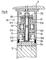
- a slot 16 (FIG. 3) extending in the longitudinal direction of this rail 13 is made in the mounting rail 13. This slot 16 opens towards the door leaf 2 and in this slot 16 a carriage 20 is slidably mounted. The portion of this carriage 20 protruding from the slot 16 is connected to the door leaf 2.
- the profile of the slot 16 in the mounting rail 13 is such that the carriage 20 can move along the mounting rail 13 and that the carriage 20 cannot leave the slot 16 perpendicular to the longitudinal direction of this slot 16.
- 6 shows a possible cross section of the mounting rail 13, this cross section simultaneously meeting the two requirements mentioned.
- inwardly projecting wall thickenings 17 and 18 (FIG. 6) which reduce the width of the slot 16 in the area of its mouth.
- the surfaces 171 and 181 of the thickenings 17 and 18 facing the interior of the slot 16 are flat, they run practically horizontally and they lie in the same plane.
- the mutually opposite surfaces 172 and 182 of the thickenings 17 and 18 are also flat and they run practically vertically, parallel to one another and at a distance from one another. This distance between the end faces 172 and 182 is smaller than the width of the groove 16.
- the carriage 20 comprises a base body 21, which has essentially the shape of a cross. Rollers 211 and 212 are mounted on the horizontal legs of this cross 21 and can roll on the horizontal surfaces 171 and 181 of the mounting rail 13. These rollers 211 and 212 are advantageously ball bearings.
- the vertical part of the cross 21 is hollow and a support pin 22 passes through this hole in the vertical part.
- an axial bearing 30 is arranged, through which the top end portion of the trunnion 22 also passes.
- a nut 23 is screwed onto the end of the support pin 22 which protrudes above and via which the support pin 22 rests on the axial bearing 30.
- the part of the pin 22 projecting downwards from the carriage 20 passes between the wall thickenings 17 and 18 of the frame web 13 and the free end part of this pin section is connected to the door leaf 2.
- the height of the carriage 20 and the trunnion 22 are dimensioned such that the lower side 34 of the door leaf 2 is located at such a distance from the floor or from the floor rail 8 that the door leaf 2 can be moved without its underside touching the floor touched.
- the carriage 20 is also in the mounting rail 13, i.e. similar to the swivel shaft 5, freely movable. This means that no separate drive device is connected to either the carriage 20 or the swivel shaft 5.
- the carrier car 20 is connected to the upper horizontal edge 33 of the door leaf 2.
- a connection plate 24 is fastened, which is practically perpendicular to the longitudinal axis of the pin 22.
- This plate 24 is attached to the top of the upper horizontal piece 33 of the door leaf 2, for example with the aid of screws.
- This attachment point of the support carriage 20 is located on the door leaf 2 at a distance from the pivot shaft 5, which makes up about two thirds of the length of the upper horizontal piece 33 of the door leaf 2 or two thirds of the length of the support rail 13 1.
- a pin 28 is embedded in each of the horizontal wing legs 33 and 34 such that the pin portion protruding from the door wing 2 projects from the wing 2.
- the portion of the respective pin 28 protruding from the door leaf 2 is pivotally mounted in an eye 29 which is designed on the free end part of the respective support arm 14 or 15.
- the distance between the respective pin 28 and the vertical piece 31 of the door leaf 2 facing the pivot shaft 5 corresponds approximately one third of the length of the horizontal piece 33 or 34 of the door leaf 2.
- the gap between the mounting rail 13 and the door leaf 2 can be covered with the help of bristles 39.
- the first of the vertical side pieces 31 of the wing 2 is located in the immediate vicinity of the pivot shaft 5. This pivot shaft 5 is thus located between the said side piece 31 of the wing 2 and the wall opening 4.
- a lock 35 is attached to the door leaf 2.
- This lock 35 is located on that vertical side of the door, which is opposite the pivot shaft 5.
- the lock 35 is at a height above the floor, which is considered advantageous for the operation of the lock 35.
- It can be a mortise door lock.
- This lock 35 is inserted into the vertical piece 32 from the outside of the second vertical piece 32 of the casement 25, which is located away from the pivot shaft 5.
- This lock 35 has door handles 36, one of which is arranged on one of the sides of the door leaf in the usual manner.
- the latch 37 and bolt 38 which are common in the mortise door lock are also present, which can engage in a strike plate or at least in corresponding openings in the adjacent vertical leg 12 of the door frame 1.
- the lock bolt 38 can be of a type known per se.
- the animal trap 38 of this lock 35 is a roller trap executed, which can snap into a correspondingly shaped opening in the vertical leg 12 of the door frame 1.
- the described design of the door enables this door to be opened by a normal actuation of the door handle 36 and by the subsequent exertion of pressure on the door leaf 2. It is irrelevant whether one exerts pressure on one or the other side of the door leaf 2 because the door leaf yields in these two cases and changes to its open position.
- the door leaf 2 In the closed position, the door leaf 2 is completely in the room opening 4 and it is practically parallel to a central plane of this opening 4.
- the swivel arms 14 and 15 lie between the horizontal lines 33 and 34 of the door leaf 2 and the horizontal sections 8 and 13 of the room or Door opening 4. The axes of these swivel arms 14 and 15 are also parallel to the plane of the door opening 4.
- the first of these latches 41 is in the upper region and the second additional latch 42 is arranged in the lower region of the door leaf 2. Openings for receiving these latches 41 and 42 are embodied in the hollow pivot shaft 5, these openings being embodied at the points on the pivot shaft 5 corresponding to the latches 41 and 42.
- a connecting member 43 or 44 leads from the respective additional latch 41 or 42 to the door lock 35.
- the lock 35 is designed such that the actuation of the additional latches 41 and 42 is coupled to the position of the latch bolt 38.
- the lock bolt 38 is extended, ie when the door is locked, the additional latches 41 and 42 are blocked in their extended position.
- the additional latches 41 and 42 cannot be pushed back into the interior of the door leaf 2 and the door cannot be opened even when the door handle 36 is actuated.
- the unlocked lock 35 on the other hand, ie when the bolt 38 is retracted into the lock 35, the additional roller latches 41 and 42 are unlocked and thus freely movable so that the door can be opened.
- FIG. 4 shows the door 2 in a first open position in section X-X and also in section X-X in a second open position in FIG. 5.
- 4 and 5 show another embodiment of the present door.
- the frame 1 of this door has a further vertical leg or post 11.
- This vertical leg 11 is shown in cross section in FIGS. 4 and 5 and it extends parallel to the pivot shaft 5.
- the upper end part of this frame leg 11 can be fastened in the lintel of the door opening 4 or can be firmly connected to the mounting rail 13.
- the lower end part of the further frame leg 11 can be embedded in the floor or can be firmly connected to the floor rail 8.
- the pivot shaft 5 is designed as a tube with a circular cross section, then the further frame leg 11 can be arranged very close to this pivot shaft 5. If the pivot shaft 5 has a square cross section, then the pivot shaft 5 must be at such a distance from the Additional frame legs 11 are located so that the corner parts of this pivot shaft 5 do not touch the frame leg 11 when pivoting the same. If the door is closed, then there is a noticeable distance between the pivot shaft 5 and this frame leg 11 in the present case. This gap can be covered by trim strips 46 and 47, one of which is attached to one of the sides of the additional frame leg 11. These trim strips 45 and 46 extend over the entire height of the door opening and they are so wide that they extend to the door leaf 2.
- trim strips 46 and 47 In the area of the swivel arms 14 and 15, the trim strips 46 and 47 have incisions running perpendicular to the longitudinal direction of the strips 46 and 47, the width of which is somewhat greater than the thickness of the swivel arms 14 and 15. Trim strips 48 and 49 can also be on the opposite vertical frame leg 12 in be attached appropriately (Figs. 2 and 3).
- Such a door can be used not only in hospitals, old people's and disabled homes, but also in industrial buildings, etc.
Landscapes
- Engineering & Computer Science (AREA)
- Mechanical Engineering (AREA)
- Structural Engineering (AREA)
- Wing Frames And Configurations (AREA)
- Hinges (AREA)
- Lock And Its Accessories (AREA)
- Seal Device For Vehicle (AREA)
- Closing And Opening Devices For Wings, And Checks For Wings (AREA)
Applications Claiming Priority (2)
| Application Number | Priority Date | Filing Date | Title |
|---|---|---|---|
| CH00838/94A CH688103A5 (de) | 1994-03-21 | 1994-03-21 | Tuer. |
| CH838/94 | 1994-03-21 |
Publications (2)
| Publication Number | Publication Date |
|---|---|
| EP0674077A1 true EP0674077A1 (fr) | 1995-09-27 |
| EP0674077B1 EP0674077B1 (fr) | 1998-12-09 |
Family
ID=4196384
Family Applications (1)
| Application Number | Title | Priority Date | Filing Date |
|---|---|---|---|
| EP95810189A Expired - Lifetime EP0674077B1 (fr) | 1994-03-21 | 1995-03-20 | Porte |
Country Status (4)
| Country | Link |
|---|---|
| EP (1) | EP0674077B1 (fr) |
| AT (1) | ATE174402T1 (fr) |
| CH (1) | CH688103A5 (fr) |
| DE (1) | DE59504457D1 (fr) |
Cited By (4)
| Publication number | Priority date | Publication date | Assignee | Title |
|---|---|---|---|---|
| FR2821384A1 (fr) * | 2001-02-27 | 2002-08-30 | Rotodor Ag | Porte a roto translation "tirez poussez" a encombrement reduit |
| FR2846028A1 (fr) | 2002-10-17 | 2004-04-23 | Rotodor Ag | Dispositif d'articulation d'un battant d'une porte |
| EP2088269A3 (fr) * | 2008-02-05 | 2010-06-23 | Bertoldo F.Lli S.N.C. | Porte, du type qui présente au moins un vantail ouvrable doté d'un mouvement combiné de translation et de rotation autour d'un axe vertical |
| CN104612559A (zh) * | 2014-08-04 | 2015-05-13 | 深圳市门老爷科技有限公司 | 用于逃生门的可调节门扇及其调节方法 |
Citations (4)
| Publication number | Priority date | Publication date | Assignee | Title |
|---|---|---|---|---|
| FR2553464A1 (fr) * | 1983-10-17 | 1985-04-19 | Nieder Pietro | Jonction articulee composee et adaptable pour portes |
| EP0370437A1 (fr) * | 1988-11-22 | 1990-05-30 | A. ARTWEGER GESELLSCHAFT m.b.H. | Porte ou fenêtre |
| DE4112851A1 (de) * | 1991-04-19 | 1992-10-22 | Beschlaege Koch Gmbh & Co Kg | Dreh-schiebetuere, insbesondere fuer rollstuhlfahrer |
| GB2268532A (en) * | 1992-06-30 | 1994-01-12 | Spilka International Limited A | Window with combined pivoting and sliding motion |
-
1994
- 1994-03-21 CH CH00838/94A patent/CH688103A5/de not_active IP Right Cessation
-
1995
- 1995-03-20 EP EP95810189A patent/EP0674077B1/fr not_active Expired - Lifetime
- 1995-03-20 AT AT95810189T patent/ATE174402T1/de not_active IP Right Cessation
- 1995-03-20 DE DE59504457T patent/DE59504457D1/de not_active Expired - Fee Related
Patent Citations (4)
| Publication number | Priority date | Publication date | Assignee | Title |
|---|---|---|---|---|
| FR2553464A1 (fr) * | 1983-10-17 | 1985-04-19 | Nieder Pietro | Jonction articulee composee et adaptable pour portes |
| EP0370437A1 (fr) * | 1988-11-22 | 1990-05-30 | A. ARTWEGER GESELLSCHAFT m.b.H. | Porte ou fenêtre |
| DE4112851A1 (de) * | 1991-04-19 | 1992-10-22 | Beschlaege Koch Gmbh & Co Kg | Dreh-schiebetuere, insbesondere fuer rollstuhlfahrer |
| GB2268532A (en) * | 1992-06-30 | 1994-01-12 | Spilka International Limited A | Window with combined pivoting and sliding motion |
Cited By (6)
| Publication number | Priority date | Publication date | Assignee | Title |
|---|---|---|---|---|
| FR2821384A1 (fr) * | 2001-02-27 | 2002-08-30 | Rotodor Ag | Porte a roto translation "tirez poussez" a encombrement reduit |
| WO2002072989A1 (fr) * | 2001-02-27 | 2002-09-19 | Rotodor Ag | Dispositif pour ' tirez ou poussez ' un battant d'une porte |
| FR2846028A1 (fr) | 2002-10-17 | 2004-04-23 | Rotodor Ag | Dispositif d'articulation d'un battant d'une porte |
| EP2088269A3 (fr) * | 2008-02-05 | 2010-06-23 | Bertoldo F.Lli S.N.C. | Porte, du type qui présente au moins un vantail ouvrable doté d'un mouvement combiné de translation et de rotation autour d'un axe vertical |
| CN104612559A (zh) * | 2014-08-04 | 2015-05-13 | 深圳市门老爷科技有限公司 | 用于逃生门的可调节门扇及其调节方法 |
| CN104612559B (zh) * | 2014-08-04 | 2017-04-05 | 深圳市门老爷科技有限公司 | 用于逃生门的可调节门扇及其调节方法 |
Also Published As
| Publication number | Publication date |
|---|---|
| CH688103A5 (de) | 1997-05-15 |
| ATE174402T1 (de) | 1998-12-15 |
| DE59504457D1 (de) | 1999-01-21 |
| EP0674077B1 (fr) | 1998-12-09 |
Similar Documents
| Publication | Publication Date | Title |
|---|---|---|
| DE8702660U1 (de) | Fenster- oder Tür-Konstruktion mit einem bewegbar gehaltenen, verriegelbaren Flügel | |
| DE202014000876U1 (de) | Beschlag eines zumindest hebbaren, vorzugsweise aber auch verschiebbaren Flügels von Fenstern oder Türen | |
| EP0021080B1 (fr) | Fenêtre ou porte levante, coulissante ou basculante | |
| EP0005764A1 (fr) | Porte ou fenêtre coulissante et basculante | |
| WO2000043625A1 (fr) | Fenetre ou porte | |
| DE4210753C2 (de) | Andruckvorrichtung zwischen dem Flügel und dem Blendrahmen einer Tür, eines Fensters od. dgl. | |
| EP0096744A2 (fr) | Ferrure pour battant oscillo-battant | |
| DE29601966U1 (de) | Zusatzschloß für Flügel von Türen, Fenstern o.dgl. | |
| WO2019158439A1 (fr) | Dispositif anti-effraction abaissable | |
| EP0674077B1 (fr) | Porte | |
| DE7816563U1 (de) | Schiebe-kipp-tuer oder -fenster | |
| DE9407569U1 (de) | Einbruchsicherung | |
| EP0572988B1 (fr) | Gâche | |
| EP1790809A2 (fr) | Arrêt de porte intégré dans un vantail de porte avec une boîte de serrure intégrée dans un mécanisme d'actionnement | |
| DE2658626B2 (de) | Schaltsperre für Treibstangenbeschläge | |
| EP0697054B1 (fr) | Dispositif permettant d'orienter des fenetres basculantes et pivotantes | |
| EP1728956A1 (fr) | Ferrure pour une porte à soulèvement et coulissement assurant contre un movement de levier de l'éxterieur | |
| DE1708430C2 (de) | Feststellvorrichtung für einen Kippflügel | |
| EP1489253A1 (fr) | Fenêtre | |
| DE19929818A1 (de) | Beschlag für ein Fenster oder eine Tür mit einer Spaltöffnungsstellung | |
| EP1498563B1 (fr) | Dispositif pour créer une fente d'aération | |
| DE60201616T2 (de) | Feststeller für Tür, Fenster dgl. mit treibstangenverschlussartigen Beschlag | |
| EP1425489B1 (fr) | Ferrure oscillobattante | |
| DE1559736A1 (de) | An- und Abdruckvorrichtung fuer die Fluegel von Kipp-Schwenkfenstern,-tueren od.dgl. | |
| DE3343774A1 (de) | Stellvorrichtung fuer schiebefluegel von fenstern, tueren od. dgl. |
Legal Events
| Date | Code | Title | Description |
|---|---|---|---|
| PUAI | Public reference made under article 153(3) epc to a published international application that has entered the european phase |
Free format text: ORIGINAL CODE: 0009012 |
|
| AK | Designated contracting states |
Kind code of ref document: A1 Designated state(s): AT BE CH DE DK FR IT LI LU NL SE |
|
| 17P | Request for examination filed |
Effective date: 19960321 |
|
| 17Q | First examination report despatched |
Effective date: 19970812 |
|
| GRAG | Despatch of communication of intention to grant |
Free format text: ORIGINAL CODE: EPIDOS AGRA |
|
| GRAG | Despatch of communication of intention to grant |
Free format text: ORIGINAL CODE: EPIDOS AGRA |
|
| GRAH | Despatch of communication of intention to grant a patent |
Free format text: ORIGINAL CODE: EPIDOS IGRA |
|
| GRAH | Despatch of communication of intention to grant a patent |
Free format text: ORIGINAL CODE: EPIDOS IGRA |
|
| GRAA | (expected) grant |
Free format text: ORIGINAL CODE: 0009210 |
|
| AK | Designated contracting states |
Kind code of ref document: B1 Designated state(s): AT BE CH DE DK FR IT LI LU NL SE |
|
| PG25 | Lapsed in a contracting state [announced via postgrant information from national office to epo] |
Ref country code: NL Free format text: LAPSE BECAUSE OF FAILURE TO SUBMIT A TRANSLATION OF THE DESCRIPTION OR TO PAY THE FEE WITHIN THE PRESCRIBED TIME-LIMIT Effective date: 19981209 Ref country code: IT Free format text: LAPSE BECAUSE OF FAILURE TO SUBMIT A TRANSLATION OF THE DESCRIPTION OR TO PAY THE FEE WITHIN THE PRE;WARNING: LAPSES OF ITALIAN PATENTS WITH EFFECTIVE DATE BEFORE 2007 MAY HAVE OCCURRED AT ANY TIME BEFORE 2007. THE CORRECT EFFECTIVE DATE MAY BE DIFFERENT FROM THE ONE RECORDED.SCRIBED TIME-LIMIT Effective date: 19981209 Ref country code: FR Free format text: LAPSE BECAUSE OF FAILURE TO SUBMIT A TRANSLATION OF THE DESCRIPTION OR TO PAY THE FEE WITHIN THE PRESCRIBED TIME-LIMIT Effective date: 19981209 |
|
| REF | Corresponds to: |
Ref document number: 174402 Country of ref document: AT Date of ref document: 19981215 Kind code of ref document: T |
|
| REG | Reference to a national code |
Ref country code: CH Ref legal event code: NV Representative=s name: PATENTANWALTSBUERO DIPL.-ING. S. V. KULHAVY + CO. Ref country code: CH Ref legal event code: EP |
|
| REF | Corresponds to: |
Ref document number: 59504457 Country of ref document: DE Date of ref document: 19990121 |
|
| PG25 | Lapsed in a contracting state [announced via postgrant information from national office to epo] |
Ref country code: SE Free format text: LAPSE BECAUSE OF FAILURE TO SUBMIT A TRANSLATION OF THE DESCRIPTION OR TO PAY THE FEE WITHIN THE PRESCRIBED TIME-LIMIT Effective date: 19990309 Ref country code: DK Free format text: LAPSE BECAUSE OF FAILURE TO SUBMIT A TRANSLATION OF THE DESCRIPTION OR TO PAY THE FEE WITHIN THE PRESCRIBED TIME-LIMIT Effective date: 19990309 |
|
| PG25 | Lapsed in a contracting state [announced via postgrant information from national office to epo] |
Ref country code: LU Free format text: LAPSE BECAUSE OF NON-PAYMENT OF DUE FEES Effective date: 19990320 |
|
| PG25 | Lapsed in a contracting state [announced via postgrant information from national office to epo] |
Ref country code: BE Free format text: LAPSE BECAUSE OF NON-PAYMENT OF DUE FEES Effective date: 19990331 |
|
| PGFP | Annual fee paid to national office [announced via postgrant information from national office to epo] |
Ref country code: AT Payment date: 19990331 Year of fee payment: 5 |
|
| NLV1 | Nl: lapsed or annulled due to failure to fulfill the requirements of art. 29p and 29m of the patents act | ||
| EN | Fr: translation not filed | ||
| PGFP | Annual fee paid to national office [announced via postgrant information from national office to epo] |
Ref country code: DE Payment date: 19990526 Year of fee payment: 5 |
|
| PGFP | Annual fee paid to national office [announced via postgrant information from national office to epo] |
Ref country code: CH Payment date: 19990618 Year of fee payment: 5 |
|
| BERE | Be: lapsed |
Owner name: BUWA A.G. Effective date: 19990331 |
|
| PLBE | No opposition filed within time limit |
Free format text: ORIGINAL CODE: 0009261 |
|
| STAA | Information on the status of an ep patent application or granted ep patent |
Free format text: STATUS: NO OPPOSITION FILED WITHIN TIME LIMIT |
|
| 26N | No opposition filed | ||
| PG25 | Lapsed in a contracting state [announced via postgrant information from national office to epo] |
Ref country code: AT Free format text: LAPSE BECAUSE OF NON-PAYMENT OF DUE FEES Effective date: 20000320 |
|
| PG25 | Lapsed in a contracting state [announced via postgrant information from national office to epo] |
Ref country code: LI Free format text: LAPSE BECAUSE OF NON-PAYMENT OF DUE FEES Effective date: 20000331 Ref country code: CH Free format text: LAPSE BECAUSE OF NON-PAYMENT OF DUE FEES Effective date: 20000331 |
|
| REG | Reference to a national code |
Ref country code: CH Ref legal event code: PL |
|
| PG25 | Lapsed in a contracting state [announced via postgrant information from national office to epo] |
Ref country code: DE Free format text: LAPSE BECAUSE OF NON-PAYMENT OF DUE FEES Effective date: 20010103 |