EP0674091A2 - Zurückziehbare Store oder Jalousie - Google Patents
Zurückziehbare Store oder Jalousie Download PDFInfo
- Publication number
- EP0674091A2 EP0674091A2 EP95200572A EP95200572A EP0674091A2 EP 0674091 A2 EP0674091 A2 EP 0674091A2 EP 95200572 A EP95200572 A EP 95200572A EP 95200572 A EP95200572 A EP 95200572A EP 0674091 A2 EP0674091 A2 EP 0674091A2
- Authority
- EP
- European Patent Office
- Prior art keywords
- cord
- rail
- blind
- movable
- shade assembly
- Prior art date
- Legal status (The legal status is an assumption and is not a legal conclusion. Google has not performed a legal analysis and makes no representation as to the accuracy of the status listed.)
- Granted
Links
Images





Classifications
-
- E—FIXED CONSTRUCTIONS
- E06—DOORS, WINDOWS, SHUTTERS, OR ROLLER BLINDS IN GENERAL; LADDERS
- E06B—FIXED OR MOVABLE CLOSURES FOR OPENINGS IN BUILDINGS, VEHICLES, FENCES OR LIKE ENCLOSURES IN GENERAL, e.g. DOORS, WINDOWS, BLINDS, GATES
- E06B9/00—Screening or protective devices for wall or similar openings, with or without operating or securing mechanisms; Closures of similar construction
- E06B9/24—Screens or other constructions affording protection against light, especially against sunshine; Similar screens for privacy or appearance; Slat blinds
- E06B9/26—Lamellar or like blinds, e.g. venetian blinds
- E06B9/36—Lamellar or like blinds, e.g. venetian blinds with vertical lamellae ; Supporting rails therefor
- E06B9/362—Travellers; Lamellae suspension stems
-
- E—FIXED CONSTRUCTIONS
- E06—DOORS, WINDOWS, SHUTTERS, OR ROLLER BLINDS IN GENERAL; LADDERS
- E06B—FIXED OR MOVABLE CLOSURES FOR OPENINGS IN BUILDINGS, VEHICLES, FENCES OR LIKE ENCLOSURES IN GENERAL, e.g. DOORS, WINDOWS, BLINDS, GATES
- E06B9/00—Screening or protective devices for wall or similar openings, with or without operating or securing mechanisms; Closures of similar construction
- E06B9/24—Screens or other constructions affording protection against light, especially against sunshine; Similar screens for privacy or appearance; Slat blinds
- E06B9/26—Lamellar or like blinds, e.g. venetian blinds
- E06B9/262—Lamellar or like blinds, e.g. venetian blinds with flexibly-interconnected horizontal or vertical strips; Concertina blinds, i.e. upwardly folding flexible screens
-
- E—FIXED CONSTRUCTIONS
- E06—DOORS, WINDOWS, SHUTTERS, OR ROLLER BLINDS IN GENERAL; LADDERS
- E06B—FIXED OR MOVABLE CLOSURES FOR OPENINGS IN BUILDINGS, VEHICLES, FENCES OR LIKE ENCLOSURES IN GENERAL, e.g. DOORS, WINDOWS, BLINDS, GATES
- E06B9/00—Screening or protective devices for wall or similar openings, with or without operating or securing mechanisms; Closures of similar construction
- E06B9/24—Screens or other constructions affording protection against light, especially against sunshine; Similar screens for privacy or appearance; Slat blinds
- E06B9/26—Lamellar or like blinds, e.g. venetian blinds
- E06B9/28—Lamellar or like blinds, e.g. venetian blinds with horizontal lamellae, e.g. non-liftable
- E06B9/30—Lamellar or like blinds, e.g. venetian blinds with horizontal lamellae, e.g. non-liftable liftable
- E06B9/32—Operating, guiding, or securing devices therefor
-
- E—FIXED CONSTRUCTIONS
- E06—DOORS, WINDOWS, SHUTTERS, OR ROLLER BLINDS IN GENERAL; LADDERS
- E06B—FIXED OR MOVABLE CLOSURES FOR OPENINGS IN BUILDINGS, VEHICLES, FENCES OR LIKE ENCLOSURES IN GENERAL, e.g. DOORS, WINDOWS, BLINDS, GATES
- E06B9/00—Screening or protective devices for wall or similar openings, with or without operating or securing mechanisms; Closures of similar construction
- E06B9/24—Screens or other constructions affording protection against light, especially against sunshine; Similar screens for privacy or appearance; Slat blinds
- E06B2009/2482—Special shape
- E06B2009/2494—Trapezoidal or triangular
-
- E—FIXED CONSTRUCTIONS
- E06—DOORS, WINDOWS, SHUTTERS, OR ROLLER BLINDS IN GENERAL; LADDERS
- E06B—FIXED OR MOVABLE CLOSURES FOR OPENINGS IN BUILDINGS, VEHICLES, FENCES OR LIKE ENCLOSURES IN GENERAL, e.g. DOORS, WINDOWS, BLINDS, GATES
- E06B9/00—Screening or protective devices for wall or similar openings, with or without operating or securing mechanisms; Closures of similar construction
- E06B9/24—Screens or other constructions affording protection against light, especially against sunshine; Similar screens for privacy or appearance; Slat blinds
- E06B9/26—Lamellar or like blinds, e.g. venetian blinds
- E06B9/262—Lamellar or like blinds, e.g. venetian blinds with flexibly-interconnected horizontal or vertical strips; Concertina blinds, i.e. upwardly folding flexible screens
- E06B2009/2625—Pleated screens, e.g. concertina- or accordion-like
Definitions
- the invention relates to a retractable blind or shade assembly for covering a polygonal contoured surface area, comprising a retractable covering member, a movable member and at least one cord member.
- Either such cords are stationary to guide the movement of movable blind or shade components such as bottom rails or such cords move themselves to induce movement of rail members and the like.
- the present invention has as its object the provision of a cording arrangement that enables the engagement of a further element while forming itself no obstruction while being guided through openings or around deflecting surfaces and pulley wheels such as are often part of a blind or shade structure.
- the blind assembly is distinguished in that said at least one cord member is provided between its terminal ends with engagement means, said engagement means being adapted to engage said movable member upon a predetermined amount of relative movement between said movable member and said at least one cord member in one direction, while otherwise relative movement between said movable member and said at least one cord member is independent of one another.
- the invention further relates to a blind or shade assembly which is in particular adapted for covering irregularly shaped window openings.
- irregularly shaped window openings have posed many problems and over time one has managed to come up with solutions for strictly triangular and trapezoidal window openings.
- polygonal window openings especially of the kind having a generally rectangular outline, but with one of the corners "cut off" so as to form a partly inclined side portion, have so far been the most difficult ones to tackle.
- the invention provides a solution for this kind of installations.
- the retractable covering member can be formed by way of example as a flexible material sheet member that is either foldable, pleatable or rollable.
- the retractable covering member can be formed as a collapsible slatted blind in which the vanes or slats may be pivotally adjustable for additional light regulation.
- the movable member can either be directly assisting in deploying or retracting the covering member or it can be represented by an auxiliary element contributing indirectly to the extensive and retractive movements.
- Figure 1 relates to a retractable triangular blind.
- the blind according to this embodiment comprises a fixed head or top rail 1 as support structure, a covering member 2, preferably made from pleated material, and a raisable bottom rail 3, connected to said pleated material.
- blind assembly is provided with an extension cord 4 close to the vertical border of the covering member.
- the extension cord 4 controls the lower most position of rail 3 and also supports the vertical border of the covering member 2 in its extended position.
- the cord arrangement for guiding and supporting the blind of figure 1 comprises a first branch of lift cord 5, which extends from a cord collector 6 to a cord guide means 7 along the length of head rail 1. From said guide means 7 the lift cord 5 crosses the distance between the head rail 1 and bottom rail 3 towards a further cord guide means 8 in bottom rail 3 and is fixed at an end of said bottom rail 3. Alternatively the cord 5 may also be fixedly held by the cord guide 8, but the illustrated connection to an end cap of the bottom rail at 15 will generally be preferred for ease of assembly.
- the structure of the cord guide means is not shown in detail as this is common art. Schematically the guide means is an opening in the rail.
- a second branch of lift cord 9 is provided in the form of two double cords 9a and 9b which are looped into each other at 10, see also figures 4a-e.
- the cord loop extends from cord collector 6 via a cord guide means 7' and 8' in rails 1 and 3 respectively and back to collector 6.
- the double cord 9 will simply act as a single cord loop.
- Eyelet 12 guides one part of the double cord 9b, whereas the other eyelet 13 guides cord 4.
- extension cord 4 is withdrawn into the head rail by an elastic member.
- the elastic member exerts a biasing force on the lowered rail which may counteract the lowering of the triangular section. Otherwise a weight could be used to obtain a biasing force.
- a weight could be used to obtain a biasing force.
- the embodiment according to figure 1 allows the elimination of any biasing force in the extension cord. Withdrawal of the extension cord in the head rail has been obtained in a different manner which will now be described in more detail.
- the looped connection 10 provides the additional function of forming an engaging member for the withdrawal of the extension cord 4.
- the transmission element 11 may be moved lengthwise of the head rail 1.
- the eyelet 13 engages the extension cord 4 which at one end is attached to the head rail at 14 and at its lower end to the bottom rail at 15.
- the length of the portion of the first branch of lift cord 5 that extends between the head rail 1 and the bottom rail 3 equals the accumulated length of portions of the second branch of lift cord 9 that extends between the head rail and the bottom rail at two locations, when this length is divided by the number of crossings between the head and bottom rail of the respective lift cord.
- the loop of cord 9 enables this cord to accommodate itself to the displacement of the cord 5 thereby eliminating any difference in cord travel amongst cords 5 and 9. It is thus seen that a single cord 5 if placed intermediate of two branches of a looped cord 9 will yield a homogenous amount of cord travel.
- the looped connection 10 at a predetermined stage of lift engages the eyelet 12 of the transmission element 11.
- cord 9 and the looped connection 10 enable the cord to travel over guide surfaces without being obstructed thereby while still reliably engaging the eyelet 12.
- cord 9b Before connecting the individual cords together in the cord connector 6, adjustment is made to cord 9b to ensure that the guide cord 4 is fully withdrawn with the blind in a raised position. This results in the proper positioning of engagement means 10.
- Modification will, however, be within the scope of the invention and should be understood to comprise any knot or bead replacing the looped connection 10 and being arranged on a single cord which may be a replacement for double cord 9. If suitable adaptions are made to allow unhindered transition over the guide surfaces also such a modified cord and engagement means may be a realistic proposition.
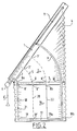
- Figure 2 schematically shows a raisable blind or shade assembly having a triangular upper blind section 2 and a rectangular lower blind section 16.
- An inclined fixed head rail 1 is disposed at the top edge of the upper section 2 and a movable bottom rail 17 is connected to a bottom edge of the lower section 16.
- An intermediate rail or stiffener member 3 is pivotally arranged between the upper and lower blind sections.
- the intermediate rail 3 thereby being pivotable with respect to the fixed rail 1 about a pivot centre adjacent to the lowermost end of the fixed rail 1.
- Lift cord 5 has a first branch extending from a cord guide means 7 in the head rail to a cord guide 8 in the intermediate rail.
- Lift cord 5 is deflected in the intermediate rail 3 to extend downwardly therefrom to a cord guide 8' left of cord guide 8.
- a second branch 18 of cord 5 thereby extends downwardly towards cord guide 19 by which the lift cord 5 is deflected towards the right to extend again upwardly from a cord guide 19'.
- a third branch 20 of lift cord 5 crosses the distance between bottom rail 17 and intermediate rail 3 and engages the latter through cord guide 8''.
- cord guide 8'' deflects cord 5 to the right of intermediate rail 3 to allow cord 5 to extend therefrom upwardly from cord guide 8'''.
- the distance between cord guide 8''' on intermediate rail 3 and cord guide 7' on head rail 1 is spanned by a fourth branch 5' of cord 5.
- Cord guide 7' deflects cord 5 downwardly to the left and towards cord connector 6.
- the lift cord 9 is again a double cord loop having an intermediate loop connection 10 similar to figures 1 and 4 a-e.
- An extension cord 4 is engaged and withdrawable by a transmission member 11 which is engaged by the loop connection 10 after a predetermined amount of lift.
- a transmission member 11 which is engaged by the loop connection 10 after a predetermined amount of lift.
- the lift cord 9, although being doubled over a large portion of its routing path is partially separated into spaced branches 21 and 22 while extending across the lower blind section 16.
- the lift cord branch 21 is deflected by cord guide 19, whereas branch 22 is being deflected by cord guides 8a, 8b and 19a.
- the portions of lift cord that are at the intermediate rail 3 and which run along the length thereof are positioned within 2/3 of the length of said intermediate rail from its pivot centre. This causes the cord friction occurring at cord guide 8, 8', 8'', 8''', 8a and 8b not to counteract the lowering of the intermediate rail 3 to any great extent. It will be clear that such friction inducing deflecting points, if concentrated at the far end of the intermediate rail away from its pivot centre may counteract lowering of rail 3 to such an extent that the bottom rail 17 lowers ahead of the intermediate rail and jams itself at the window side. This would be objectionable. It will also be seen that the cord branches are symmetrically arranged in the rectangular bottom portion 16, with branches of cord 5 and 9 balanced on either side of the middle to allow parallel lifting of the bottom rail 17. This effectively eliminates skewing of the bottom rail.
- the embodiment according to figure 3 is related to a blind, adapted to be used in a pentagonal opening or window.
- the opening comprises a top side 31, a bottom side 32, a left hand vertical side 33, a right hand vertical side 34 and a sloping side 35, connecting the top side 31 and left hand side 33.
- the blind itself is formed by a pleated material, having a pentagonal form in the extended situation, said blind comprising a trapezoidal section 36, and a rectangular section 37.
- the pleated material of the trapezoidal section 36 is provided with a movable top rail 38, and a movable intermediate rail 39.
- the rectangular section 37 is bordered by said intermediate rail 39 and a fixed bottom rail 40.
- the blind itself can be brought from the open to the closed position and vice versa by moving the top rail 38 manually in upward and downward direction.
- the top rail 38 is provided with two cord loops 43 and 44 respectively.
- the cord loops comprise two parts of a double cord 43a and 43b, which are connected to each other at 10, comparable with the looped connection in figures 1, 2 and 4a-e.
- the cord loop 44 is also divided in two parts 44a and 44b, being also connected at 10 forming a looped connection.
- Both cord loops 43, 44 are slidably guided through the intermediate rail 39, the bottom rail 40 and the head rails 41, 42 respectively. From the head rail 41 the end portions of the parts 43b, 44b are routed back to the movable rail 38, where the extremities are connected to a biasing spring 45. The extremities of the cord parts 43b, 44b are connected to the movable rail 38 at 47, 48 respectively.
- the position of the movable rail 38 with respect to the intermediate rail 39 is such that the looped connection 10 is in engagement with the bar 46. So when moving the top rail 38 upwards the intermediate rail 39 will be taken along with this movement as the looped connection 10 will engage the bar 46 in the upward movement. In this way the complete blind can be closed when moving the top rail 45 more upwardly beyond the position illustrated in figure 3.
- the intermediate rail 39 When lowering the head rail 38 in downward direction, the intermediate rail 39 will still be supported from the looped connection 10 of the two cords 43, 44, but when reaching the bottom rail 40, the looped connection 10 will become free of the bar 46 and the cord portions 43a, 44a can move freely past the bar and through the bottom rail 40. Lowering the movable rail 38 further downwards, the complete trapezoidal section can be folded to uncover the pentagonal opening.
- a looped connection 10 of a double cord said looped connection forming an engagement means in the cord loop, said engagement means co-operating with an abutting member, like the eyelet 12 in figure 1, 2 or the bar 46 in figure 3.
- FIG. 4a-e A plurality of arrangements possible with such a looped connection is depicted in figure 4a-e.
- Figure 4a discloses a looped connection co-operating with an eye-let 49, comparable with an eye-let 12 of the transmission member 11 in figures 1 and 2.
- Figure 4b discloses a looped connection 10 co-operating with an abutting member in the form of a cord or thread 50, comparable with the abutting member 46 in the embodiment of figure 3.
- Figure 4c is an alternative of the cord 50 in figure 4b, and the abutting member is formed here by a bar or rod 51.
- the abutting member is formed by a disk 52 provided with two apertures 53, through which the parts of the one cord portion are slidably guided.
- Figure 4e is a double embodiment, wherein two cord loops are parallel to each other, whereas both are provided with a looped connection 10, 10' respectively.
- the abutting member 52' is provided with four apertures 53' for taking up the cord parts of the one loop and the other loop.
- the arrow P3 indicates the free movement of the cord loop along the abutting member, whereas in the reverse direction the arrow P4 indicates the blocked movement, wherein the looped connection will abut to the abutting member.
- FIG 5 such a cord loop having a looped connection 10 is also applicable to blinds or shades of a different kind.
- Figure 5 is depicting an embodiment of a so-called slat-blind, wherein the slats 55 are each suspended to a carrier 56, which are slidably guided in a head rail 57.
- a cord loop 58 is led through the head rail 57 and depends from the head rail downwards and will be biased by a weight 59 with a return pulley.
- the slats 55 can be drawn to the right in figure 5 by connecting the right hand outer carrier 56 to the terminal parts of the cord loop 58 at 54, whereupon each of the carriers 56 will trail its neighbouring carrier by means of spacer means as is well-known in the art and therefor not described further.
- the spacer means will provide a predetermined distance between adjacent carriers 56 when the slats 55 are evenly distributed over the head rail 57.
- a driving shaft 60 is provided to effect angular adjustment of the slats 55 about a vertical pivot (not shown but well-known in the art and therefor not further described).
- the driving shaft 60 must be supported, when all the slats 55 are retracted to the left hand side in figure 5.
- Such a support can be embodied by an auxiliary carrier 60' slidably guided in the head rail 57.
- the cord loop 58 is embodied by double cords having a looped connection 10 shown at the right hand side of the carrier 60', said looped connection is provided with an abutting member such as a disc 52 similar to that of figure 4d.
- the cord 58 When pulling the front portion of the cord loop 58 in the direction of arrow P3, the cord 58 can freely move with respect to the auxiliary carrier 60' and when the outermost carrier 56 will abut the auxiliary carrier 60' both carriers will be pulled to the extreme right hand end of the head rail 57.
- the embodiment of figure 6 is a blind assembly adapted to be used in a pentagonal window area having parallel bottom and top edges 61, 62 and a partly perpendicular side edge 63 followed by an inclined top portion 64.
- the other side edge 71 is shown as a fully perpendicular side edge, but could also be a mirror image of sides 63 and 64.
- the blind material which could be a pleated, cellular or slatted blind has a rectangular bottom section 5 and a trapezoidal top section 6.
- a fixed rail member 67 Along the bottom edge of the window opening is affixed a fixed rail member 67 and along the top edge 62 is affixed a further fixed rail member 69. Movable between these fixed rail members is a movable rail member 68, which is parallel to said fixed rail members and is movable from rail member 67 towards rail member 69 to close the blind.
- a cord loop is provided to guide and retain the movable rails 68 and 70.
- the cord loop 72 is closed by an elastic means, such as a spring 73 to provide tension in said cord loop. Further it can be seen in figure 2 that the cord loop 72 crosses over at 74 from left to right in the movable rail 68 and crosses over back again in a similar fashion in rail 70.
- This eight-shaped cord looping provides for the parallel guiding of the movable rails in relation to the fixed rails and the cord tension together with friction at the deflecting point will retain the movable rails in any adjusted position.
- cord loop additionally extends through openings in the shading material sections 65 and 66, as is conventional in the art, then support and guiding for the blind material is also provided.
- Figure 6 illustrates a further eight-shaped cord loop 75, somewhat similar to the cord loop 72, but wider in shape to providing for additional support and guiding of the rectangular section.
- FIG. 6 shows a left hand guide cord 76, which is provided for the support and guiding of the inclined edge 77 of trapezoidal section 66.
- Guide cord 76 is provided with length compensating means in the form of a spring tensioned return loop 78, tensioned by a spring 79.
- the length compensation means 78, 79 are conveniently accommodated in the fixed bottom rail 67.
- a guide cord 80 may be provided at the right hand edge 71.
- FIG. 6 shows an extension limiting cord 81, which serves to limit expansion of the trapezoidal blind section.
- This extension limiting cord 81 is payed out from the movable intermediate rail 70 and comprises the necessary return loop 82, 83, end stops 84, 85 and spring means 86, 87 to supply and retract the required amount of length.
- the extension cord 81 ensures that the blind section is not overstretched and that blind section 65 and movable bar 70 will also follow the movement of said movable top bar 8.
- rectangular blind section 65 could be provided with an extension limiting cord if desired.
- FIG. 7 A further embodiment of the invention is shown in figure 7. Again the window area is formed by parallel top and bottom edges 101 and 102.
- Fixed rails 106 and 107 are mounted along the bottom and top edges respectively and movable beams 108 and 109 are mounted in between for movement towards the fixed top rail 107.
- the embodiment shown in figure 7 is very similar to that of figure 2 but has a cord arrangement adapted for blinds of greater width dimensions.
- the arrangement of headrail 91, intermediate rail or stiffener member 93 and bottom rail 95 is similar to previous embodiments.
- a triangular blind section 97 and a rectangular blind section 99 may be arranged in the areas defined by the rails 91, 93 and 95. It should be noted, however, that the arrangement of blind sections is according to requirements. One could for instance chose a different kind of blind material for the triangular section as for the rectangular section. Also, one could leave the triangular area 97 open and only have a blind member between the horizontal rails 93 and 95.
- the covering members of the blind are passive elements in the process of raising and lowering whereas the individual rail members and cords are the more active elements. While functioning as a shading device the covering members will have a more active role than any of the other elements. It will thus be clear that the arrangement of lift cords, guiding cords and rails is rather independent of the precise nature of the blind or shading device deployed or raised therewith. It is seen in figure 7 that lift cord 101 is routed almost symmetrically to the other lift cord 103. More in particular lift cord 101 crosses the distance between the head rail 91 and the intermediate member 93 along the path 10t and along path 106.
- the other lift cord 103 crosses the distance between the head rail and the intermediate member a similar number of times and along paths 107 and 108 which are of similar length to the paths 105 and 106 of cord 101.
- Cord guiding means and cord deflecting elements are generally similar to those described in connection with figure 2 and are therefore not separately referred to in figure 7. Similar considerations apply to the lift cord collecting and operating element as well the extension cord along the vertical edge.
Landscapes
- Engineering & Computer Science (AREA)
- Structural Engineering (AREA)
- Architecture (AREA)
- Civil Engineering (AREA)
- Blinds (AREA)
- Fittings On The Vehicle Exterior For Carrying Loads, And Devices For Holding Or Mounting Articles (AREA)
- Operating, Guiding And Securing Of Roll- Type Closing Members (AREA)
- Storing, Repeated Paying-Out, And Re-Storing Of Elongated Articles (AREA)
Applications Claiming Priority (6)
| Application Number | Priority Date | Filing Date | Title |
|---|---|---|---|
| EP94200602 | 1994-03-08 | ||
| EP94200603 | 1994-03-08 | ||
| EP94200603 | 1994-03-08 | ||
| EP94200602 | 1994-03-08 | ||
| EP94201822 | 1994-06-23 | ||
| EP94201822 | 1994-06-23 |
Publications (3)
| Publication Number | Publication Date |
|---|---|
| EP0674091A2 true EP0674091A2 (de) | 1995-09-27 |
| EP0674091A3 EP0674091A3 (de) | 1995-12-13 |
| EP0674091B1 EP0674091B1 (de) | 1999-11-03 |
Family
ID=27235970
Family Applications (1)
| Application Number | Title | Priority Date | Filing Date |
|---|---|---|---|
| EP95200572A Expired - Lifetime EP0674091B1 (de) | 1994-03-08 | 1995-03-08 | Zurückziehbare Store oder Jalousie |
Country Status (5)
| Country | Link |
|---|---|
| US (1) | US5860464A (de) |
| EP (1) | EP0674091B1 (de) |
| AT (1) | ATE186370T1 (de) |
| CA (1) | CA2144220C (de) |
| DE (1) | DE69513066T2 (de) |
Cited By (6)
| Publication number | Priority date | Publication date | Assignee | Title |
|---|---|---|---|---|
| DE29702174U1 (de) * | 1997-02-08 | 1998-07-09 | Hüppe Form Sonnenschutzsysteme GmbH, 26133 Oldenburg | Faltjalousie |
| WO2003040511A1 (en) * | 2001-11-08 | 2003-05-15 | Newell Window Furnishings, Inc. | Cordless blind |
| EP1327742A3 (de) * | 2002-01-04 | 2004-04-28 | VKR Holding A/S | Vorhang für nichtrechteckige Flächen |
| EP1416115A1 (de) * | 2002-10-31 | 2004-05-06 | Nien Made Enterprise Co., Ltd. | Jalousie mit mehreren Verdunkelungssektionen |
| EP1555382A1 (de) * | 2004-01-13 | 2005-07-20 | Hunter Douglas Industries B.V. | Zurückziehbare Jalousie |
| EP2037074A3 (de) * | 2007-09-14 | 2013-12-25 | Hunter Douglas Industries Switzerland GmbH | Vorrichtung zum mindestens teilweisen Verschatten |
Families Citing this family (16)
| Publication number | Priority date | Publication date | Assignee | Title |
|---|---|---|---|---|
| US6923237B2 (en) * | 1999-02-05 | 2005-08-02 | Brian G. Workman | Mechanism for bottom up shades |
| US6478071B1 (en) * | 1999-02-05 | 2002-11-12 | Brian G. Workman | Sliding headrail and shade leveling system for specialty window shades |
| US6431245B1 (en) * | 2000-12-19 | 2002-08-13 | Gee Mei Handicraft Company Limited | Window shade |
| EP1837478A1 (de) * | 2004-12-28 | 2007-09-26 | Seiki Hanbai Co., Ltd. | Abschirmvorrichtung |
| US20060231214A1 (en) * | 2005-04-14 | 2006-10-19 | William Whyte | Top and bottom stacking blind |
| US7509989B2 (en) * | 2005-12-05 | 2009-03-31 | Dung Viet Pham | Window blind system |
| DK2034124T3 (en) * | 2007-09-05 | 2018-03-12 | Hunter Douglas Ind Bv | Window covering device with lanyard |
| US8051505B1 (en) * | 2008-04-02 | 2011-11-08 | Horton Karl G | Spa cover and method |
| JP6109735B2 (ja) | 2010-05-28 | 2017-04-05 | ハンター ダグラス インコーポレイテッド | 回転モータにより電力を供給される建築物の開口部遮蔽物 |
| US9335753B2 (en) | 2011-02-07 | 2016-05-10 | Hunter Douglas Inc. | Architectural opening coverings and methods |
| US9765568B2 (en) | 2011-10-03 | 2017-09-19 | Hunter Douglas Inc. | Methods and apparatus to control architectural opening covering assemblies |
| US9982481B2 (en) * | 2015-11-25 | 2018-05-29 | Mario M Marocco | Arch window covering with control |
| CN108237877B (zh) * | 2018-02-11 | 2024-03-22 | 周天然 | 汽车侧窗窗帘固定架 |
| USD900474S1 (en) | 2019-05-31 | 2020-11-03 | Chris J. Katopis | Backpack umbrella |
| IT202100009542A1 (it) * | 2021-04-15 | 2022-10-15 | Lci Italy Srl | Dispositivo di oscuramento di un finestrino di un veicolo |
| CN114275117B (zh) * | 2021-11-02 | 2022-11-25 | 中船澄西船舶修造有限公司 | 一种船台滑道保护罩 |
Family Cites Families (15)
| Publication number | Priority date | Publication date | Assignee | Title |
|---|---|---|---|---|
| US4687038A (en) * | 1983-12-19 | 1987-08-18 | Coronet Industries, Inc. | Blind construction |
| US4647488B1 (en) * | 1984-08-07 | 1994-12-27 | Hunter Douglas | Method and apparatus for mounting and sealing honeycomb insulation |
| US4673018A (en) * | 1984-11-13 | 1987-06-16 | Verosol Usa Inc. | Sun blind |
| US4842034A (en) * | 1985-10-09 | 1989-06-27 | Elkhart Door, Incorporated | Window shade |
| NL8600845A (nl) * | 1986-04-02 | 1987-11-02 | Verosol Bv | Opvouwbare gordijnschermkonstruktie voor een driehoekig venster. |
| US4762159A (en) * | 1986-09-18 | 1988-08-09 | Cooper Industries | Shade system |
| US5092383A (en) * | 1987-04-01 | 1992-03-03 | Bw-Usa, Inc. | Shade for non-rectangular opening |
| US4799524A (en) * | 1987-07-21 | 1989-01-24 | Claude Guermonprez | Protection and/or decorative device for apertures in walls, windows and the like |
| US4901419A (en) * | 1989-01-03 | 1990-02-20 | Home Fashions, Inc. | A-frame window covering mounting arrangement |
| JP2540210B2 (ja) * | 1989-06-19 | 1996-10-02 | 株式会社坂戸工作所 | 破砕機 |
| DE9111586U1 (de) * | 1991-09-13 | 1991-11-21 | Brown, Alfred Stanley, Little Billing, Northampton | Vorhang für eine nicht-rechtwinklige, insbesondere trapezförmige Fläche |
| DE9215886U1 (de) * | 1992-11-23 | 1994-04-07 | HANSA Sicht- und Sonnenschutz GmbH, 22523 Hamburg | Zusammenfaltbarer Behang für eine Fenster- oder Türöffnung |
| DE9401562U1 (de) * | 1993-08-18 | 1994-03-24 | Karl H. Blöcker GmbH & Co, 28217 Bremen | Faltenvorhang für vieleckige Flächen |
| US5495883A (en) * | 1994-08-05 | 1996-03-05 | Verosol Usa Inc. | Window shade cord safety shroud |
| US5566734A (en) * | 1995-02-23 | 1996-10-22 | Levy; Arnold | Pleated window shade |
-
1995
- 1995-03-08 AT AT95200572T patent/ATE186370T1/de not_active IP Right Cessation
- 1995-03-08 CA CA002144220A patent/CA2144220C/en not_active Expired - Fee Related
- 1995-03-08 EP EP95200572A patent/EP0674091B1/de not_active Expired - Lifetime
- 1995-03-08 DE DE69513066T patent/DE69513066T2/de not_active Expired - Lifetime
-
1997
- 1997-01-10 US US08/781,744 patent/US5860464A/en not_active Expired - Lifetime
Cited By (8)
| Publication number | Priority date | Publication date | Assignee | Title |
|---|---|---|---|---|
| DE29702174U1 (de) * | 1997-02-08 | 1998-07-09 | Hüppe Form Sonnenschutzsysteme GmbH, 26133 Oldenburg | Faltjalousie |
| WO2003040511A1 (en) * | 2001-11-08 | 2003-05-15 | Newell Window Furnishings, Inc. | Cordless blind |
| US6644373B2 (en) | 2001-11-08 | 2003-11-11 | Newell Window Furnishings, Inc. | Cordless blind |
| EP1327742A3 (de) * | 2002-01-04 | 2004-04-28 | VKR Holding A/S | Vorhang für nichtrechteckige Flächen |
| EP1416115A1 (de) * | 2002-10-31 | 2004-05-06 | Nien Made Enterprise Co., Ltd. | Jalousie mit mehreren Verdunkelungssektionen |
| EP1555382A1 (de) * | 2004-01-13 | 2005-07-20 | Hunter Douglas Industries B.V. | Zurückziehbare Jalousie |
| US7261137B2 (en) | 2004-01-13 | 2007-08-28 | Hunter Douglas Industries Bv | Retractable blind assembly |
| EP2037074A3 (de) * | 2007-09-14 | 2013-12-25 | Hunter Douglas Industries Switzerland GmbH | Vorrichtung zum mindestens teilweisen Verschatten |
Also Published As
| Publication number | Publication date |
|---|---|
| EP0674091B1 (de) | 1999-11-03 |
| US5860464A (en) | 1999-01-19 |
| CA2144220C (en) | 2005-08-23 |
| CA2144220A1 (en) | 1995-09-09 |
| EP0674091A3 (de) | 1995-12-13 |
| ATE186370T1 (de) | 1999-11-15 |
| DE69513066D1 (de) | 1999-12-09 |
| DE69513066T2 (de) | 2000-02-17 |
Similar Documents
| Publication | Publication Date | Title |
|---|---|---|
| US5860464A (en) | Retractable blind or shade assembly | |
| CA2106886C (en) | Adjustable expandable and collapsible shade | |
| KR101861863B1 (ko) | 건축물 개방구용 탑다운/바텀업 덮개를 위한 코드 장력 제어 | |
| DK1776025T3 (en) | Window coverings. | |
| CA2409802C (en) | Combination blind with multiple shading sections | |
| US5287908A (en) | Window covering assembly | |
| EP1625273B1 (de) | Raffrollo | |
| US5918657A (en) | Holeless window blind | |
| US10550635B2 (en) | Window covering control apparatus | |
| US20070175593A1 (en) | Roman shade with folding sheets | |
| US20050155720A1 (en) | Roman shade capable of adjusting light transmittance | |
| AU2004222816A1 (en) | Cord tensioner | |
| US5769140A (en) | Holeless window blind | |
| EP0742339A2 (de) | Schutzvorrichtung für Gebäudeöffnungen | |
| US20040020605A1 (en) | Vertical retractable blind | |
| EP1555382B1 (de) | Zurückziehbare Jalousie | |
| US6923237B2 (en) | Mechanism for bottom up shades | |
| CN212027612U (zh) | 一种多控制窗帘 | |
| KR20110134816A (ko) | 윈도우 덮개 | |
| DE29710850U1 (de) | Lamellenjalousie | |
| US4254815A (en) | Curtain supporting and positioning combination | |
| EP4219877B1 (de) | Einziehbare jalousieanordnung | |
| US3418752A (en) | Removable covering | |
| DE9215886U1 (de) | Zusammenfaltbarer Behang für eine Fenster- oder Türöffnung | |
| WO1992015765A1 (de) | Faltjalousie |
Legal Events
| Date | Code | Title | Description |
|---|---|---|---|
| PUAI | Public reference made under article 153(3) epc to a published international application that has entered the european phase |
Free format text: ORIGINAL CODE: 0009012 |
|
| AK | Designated contracting states |
Kind code of ref document: A2 Designated state(s): AT BE CH DE DK ES FR GB IE IT LI NL PT SE |
|
| PUAL | Search report despatched |
Free format text: ORIGINAL CODE: 0009013 |
|
| AK | Designated contracting states |
Kind code of ref document: A3 Designated state(s): AT BE CH DE DK ES FR GB IE IT LI NL PT SE |
|
| 17P | Request for examination filed |
Effective date: 19960604 |
|
| 17Q | First examination report despatched |
Effective date: 19961213 |
|
| GRAG | Despatch of communication of intention to grant |
Free format text: ORIGINAL CODE: EPIDOS AGRA |
|
| RAP1 | Party data changed (applicant data changed or rights of an application transferred) |
Owner name: HUNTER DOUGLAS INDUSTRIES B.V. |
|
| GRAG | Despatch of communication of intention to grant |
Free format text: ORIGINAL CODE: EPIDOS AGRA |
|
| GRAH | Despatch of communication of intention to grant a patent |
Free format text: ORIGINAL CODE: EPIDOS IGRA |
|
| GRAH | Despatch of communication of intention to grant a patent |
Free format text: ORIGINAL CODE: EPIDOS IGRA |
|
| GRAA | (expected) grant |
Free format text: ORIGINAL CODE: 0009210 |
|
| AK | Designated contracting states |
Kind code of ref document: B1 Designated state(s): AT BE CH DE DK ES FR GB IE IT LI NL PT SE |
|
| PG25 | Lapsed in a contracting state [announced via postgrant information from national office to epo] |
Ref country code: SE Free format text: THE PATENT HAS BEEN ANNULLED BY A DECISION OF A NATIONAL AUTHORITY Effective date: 19991103 Ref country code: LI Free format text: LAPSE BECAUSE OF FAILURE TO SUBMIT A TRANSLATION OF THE DESCRIPTION OR TO PAY THE FEE WITHIN THE PRESCRIBED TIME-LIMIT Effective date: 19991103 Ref country code: IT Free format text: LAPSE BECAUSE OF FAILURE TO SUBMIT A TRANSLATION OF THE DESCRIPTION OR TO PAY THE FEE WITHIN THE PRESCRIBED TIME-LIMIT;WARNING: LAPSES OF ITALIAN PATENTS WITH EFFECTIVE DATE BEFORE 2007 MAY HAVE OCCURRED AT ANY TIME BEFORE 2007. THE CORRECT EFFECTIVE DATE MAY BE DIFFERENT FROM THE ONE RECORDED. Effective date: 19991103 Ref country code: FR Free format text: LAPSE BECAUSE OF FAILURE TO SUBMIT A TRANSLATION OF THE DESCRIPTION OR TO PAY THE FEE WITHIN THE PRESCRIBED TIME-LIMIT Effective date: 19991103 Ref country code: ES Free format text: THE PATENT HAS BEEN ANNULLED BY A DECISION OF A NATIONAL AUTHORITY Effective date: 19991103 Ref country code: CH Free format text: LAPSE BECAUSE OF FAILURE TO SUBMIT A TRANSLATION OF THE DESCRIPTION OR TO PAY THE FEE WITHIN THE PRESCRIBED TIME-LIMIT Effective date: 19991103 Ref country code: BE Free format text: LAPSE BECAUSE OF FAILURE TO SUBMIT A TRANSLATION OF THE DESCRIPTION OR TO PAY THE FEE WITHIN THE PRESCRIBED TIME-LIMIT Effective date: 19991103 Ref country code: AT Free format text: LAPSE BECAUSE OF FAILURE TO SUBMIT A TRANSLATION OF THE DESCRIPTION OR TO PAY THE FEE WITHIN THE PRESCRIBED TIME-LIMIT Effective date: 19991103 |
|
| REF | Corresponds to: |
Ref document number: 186370 Country of ref document: AT Date of ref document: 19991115 Kind code of ref document: T |
|
| REG | Reference to a national code |
Ref country code: CH Ref legal event code: EP |
|
| REF | Corresponds to: |
Ref document number: 69513066 Country of ref document: DE Date of ref document: 19991209 |
|
| REG | Reference to a national code |
Ref country code: IE Ref legal event code: FG4D |
|
| PG25 | Lapsed in a contracting state [announced via postgrant information from national office to epo] |
Ref country code: PT Free format text: LAPSE BECAUSE OF FAILURE TO SUBMIT A TRANSLATION OF THE DESCRIPTION OR TO PAY THE FEE WITHIN THE PRESCRIBED TIME-LIMIT Effective date: 20000203 Ref country code: DK Free format text: LAPSE BECAUSE OF FAILURE TO SUBMIT A TRANSLATION OF THE DESCRIPTION OR TO PAY THE FEE WITHIN THE PRESCRIBED TIME-LIMIT Effective date: 20000203 |
|
| PG25 | Lapsed in a contracting state [announced via postgrant information from national office to epo] |
Ref country code: IE Free format text: LAPSE BECAUSE OF NON-PAYMENT OF DUE FEES Effective date: 20000308 |
|
| EN | Fr: translation not filed | ||
| REG | Reference to a national code |
Ref country code: CH Ref legal event code: PL |
|
| PLBE | No opposition filed within time limit |
Free format text: ORIGINAL CODE: 0009261 |
|
| STAA | Information on the status of an ep patent application or granted ep patent |
Free format text: STATUS: NO OPPOSITION FILED WITHIN TIME LIMIT |
|
| 26N | No opposition filed | ||
| REG | Reference to a national code |
Ref country code: IE Ref legal event code: MM4A |
|
| REG | Reference to a national code |
Ref country code: GB Ref legal event code: IF02 |
|
| PGFP | Annual fee paid to national office [announced via postgrant information from national office to epo] |
Ref country code: GB Payment date: 20130306 Year of fee payment: 19 Ref country code: DE Payment date: 20130306 Year of fee payment: 19 |
|
| PGFP | Annual fee paid to national office [announced via postgrant information from national office to epo] |
Ref country code: NL Payment date: 20130309 Year of fee payment: 19 |
|
| REG | Reference to a national code |
Ref country code: DE Ref legal event code: R119 Ref document number: 69513066 Country of ref document: DE |
|
| REG | Reference to a national code |
Ref country code: NL Ref legal event code: V1 Effective date: 20141001 |
|
| GBPC | Gb: european patent ceased through non-payment of renewal fee |
Effective date: 20140308 |
|
| PG25 | Lapsed in a contracting state [announced via postgrant information from national office to epo] |
Ref country code: DE Free format text: LAPSE BECAUSE OF NON-PAYMENT OF DUE FEES Effective date: 20141001 Ref country code: GB Free format text: LAPSE BECAUSE OF NON-PAYMENT OF DUE FEES Effective date: 20140308 |
|
| REG | Reference to a national code |
Ref country code: DE Ref legal event code: R119 Ref document number: 69513066 Country of ref document: DE Effective date: 20141001 |
|
| PG25 | Lapsed in a contracting state [announced via postgrant information from national office to epo] |
Ref country code: NL Free format text: LAPSE BECAUSE OF NON-PAYMENT OF DUE FEES Effective date: 20141001 |