EP1555382A1 - Zurückziehbare Jalousie - Google Patents
Zurückziehbare Jalousie Download PDFInfo
- Publication number
- EP1555382A1 EP1555382A1 EP05250089A EP05250089A EP1555382A1 EP 1555382 A1 EP1555382 A1 EP 1555382A1 EP 05250089 A EP05250089 A EP 05250089A EP 05250089 A EP05250089 A EP 05250089A EP 1555382 A1 EP1555382 A1 EP 1555382A1
- Authority
- EP
- European Patent Office
- Prior art keywords
- rail
- cord
- covering material
- guide
- blind
- Prior art date
- Legal status (The legal status is an assumption and is not a legal conclusion. Google has not performed a legal analysis and makes no representation as to the accuracy of the status listed.)
- Granted
Links
- 230000001154 acute effect Effects 0.000 claims abstract description 6
Images




Classifications
-
- E—FIXED CONSTRUCTIONS
- E06—DOORS, WINDOWS, SHUTTERS, OR ROLLER BLINDS IN GENERAL; LADDERS
- E06B—FIXED OR MOVABLE CLOSURES FOR OPENINGS IN BUILDINGS, VEHICLES, FENCES OR LIKE ENCLOSURES IN GENERAL, e.g. DOORS, WINDOWS, BLINDS, GATES
- E06B9/00—Screening or protective devices for wall or similar openings, with or without operating or securing mechanisms; Closures of similar construction
- E06B9/24—Screens or other constructions affording protection against light, especially against sunshine; Similar screens for privacy or appearance; Slat blinds
- E06B9/26—Lamellar or like blinds, e.g. venetian blinds
- E06B9/262—Lamellar or like blinds, e.g. venetian blinds with flexibly-interconnected horizontal or vertical strips; Concertina blinds, i.e. upwardly folding flexible screens
-
- E—FIXED CONSTRUCTIONS
- E06—DOORS, WINDOWS, SHUTTERS, OR ROLLER BLINDS IN GENERAL; LADDERS
- E06B—FIXED OR MOVABLE CLOSURES FOR OPENINGS IN BUILDINGS, VEHICLES, FENCES OR LIKE ENCLOSURES IN GENERAL, e.g. DOORS, WINDOWS, BLINDS, GATES
- E06B9/00—Screening or protective devices for wall or similar openings, with or without operating or securing mechanisms; Closures of similar construction
- E06B9/24—Screens or other constructions affording protection against light, especially against sunshine; Similar screens for privacy or appearance; Slat blinds
- E06B2009/2482—Special shape
- E06B2009/2494—Trapezoidal or triangular
-
- E—FIXED CONSTRUCTIONS
- E06—DOORS, WINDOWS, SHUTTERS, OR ROLLER BLINDS IN GENERAL; LADDERS
- E06B—FIXED OR MOVABLE CLOSURES FOR OPENINGS IN BUILDINGS, VEHICLES, FENCES OR LIKE ENCLOSURES IN GENERAL, e.g. DOORS, WINDOWS, BLINDS, GATES
- E06B9/00—Screening or protective devices for wall or similar openings, with or without operating or securing mechanisms; Closures of similar construction
- E06B9/24—Screens or other constructions affording protection against light, especially against sunshine; Similar screens for privacy or appearance; Slat blinds
- E06B9/26—Lamellar or like blinds, e.g. venetian blinds
- E06B9/262—Lamellar or like blinds, e.g. venetian blinds with flexibly-interconnected horizontal or vertical strips; Concertina blinds, i.e. upwardly folding flexible screens
- E06B2009/2625—Pleated screens, e.g. concertina- or accordion-like
Definitions
- This invention relates to a retractable blind assembly for covering an irregularly shaped window area with an upper triangular portion and a lower rectangular portion.
- This invention particularly relates to a blind which can be retracted and extended by pulling and releasing a plurality of pull cords.
- this invention relates to a blind (1), including:
- Figure 1 shows a retractable cord-operated blind 1 with a fixed inclined head rail or top rail 5 as a support structure and a raisable horizontally-extending bottom rail 11.
- a middle rail 7 that is pivotable with respect to the head rail 5 about a pivot center that is adjacent to the lowermost left end of the head rail.
- Attached to the top, middle and bottom rails 5, 7, 11 are a pair of lift cords 17,19 which extend, between the rails, through perforations in a covering member 23.
- the top and bottom edges of the covering member 23 are attached to the top and bottom rails 5 and 11, and a middle portion of the covering member is attached to the middle rail 7.
- the covering material 23 has a generally triangular top portion and a generally rectangular bottom portion, and it is preferably made from a pleated material.
- the covering material 23 in the top section 3 has an unattached short apex 13 about the pivot center of the top section and an opposite, unattached, long side 15 when the covering material is extended.
- the blind 1 has a vertically-movable cord collector 21 outside of the blind. Attached to the cord connector 21 are both ends 20,22 of each of a pair of lift cords 17,19.
- the lift cords 17,19 extend from, and return to, the common cord collector 21 and are routed through, and deflected by, the head, middle and bottom rails 5,7,11 as shown in Figure 1.
- a depending cord member 25 can manually actuate the collector 21. In this regard, the cord member 25 can be used to raise and lower the collector 21 to raise and lower the middle and bottom rails 7,11 and thereby retract and extend the covering member 23 as described below.
- the routing of the first lift cord 17 in the blind 1 in accordance with this invention is as follows (with reference to Figure 1).
- the first lift cord 17 extends rightwardly through the head rail 5, away from the collector 21, and at a first guide in the bottom of the head rail, the first lift cord 17 extends downwardly to a first guide through the middle rail 7 that is adjacent -- i.e., just to the right of -- the apex 13 of the covering material 23 in the top section 3 and adjacent the left end of the middle rail.
- the first lift cord 17 then extends downwardly through the middle rail 7 to a first guide in the top of the bottom rail 11, adjacent its left end, and then rightwardly through the bottom rail to a second guide in the top of the bottom rail.
- the first lift cord then extends upwardly to a second guide in the bottom of the middle rail 7, midway between its ends, and then rightwardly through the middle rail to a third guide in the top of the middle rail, adjacent its right end.
- the first lift cord then extends upwardly, adjacent to - i.e., just to the left of -- the long side 15 of the covering material 23 in the top section 3, to a second guide in the bottom of the head rail 5 and then leftwardly through the head rail back to the collector 21.
- the routing of the second lift cord 19 in the blind 1 in accordance with this invention is as follows (with reference to Figure 1).
- the second lift cord 19 also extends rightwardly through the head rail 5, away from the collector 21, and at a third guide in the bottom of the head rail -- midway between the first and second guides in the head rail -- the second lift cord 19 extends downwardly to a fourth guide through the middle rail 7.
- the fourth guide in the middle rail 7 can be adjacent to -- i.e., just to the left of -- the second guide in the middle rail as shown schematically in Figure 1, but preferably, the second and fourth guides in the middle rail are coaxial.
- the second lift cord 19 then extends downwardly through the fourth guide in the middle rail to a third guide in the top of the bottom rail 11.
- the third guide in the top of the bottom rail 11 can be adjacent to -- i.e., just to the left of -- the second guide in the bottom rail as shown schematically in Figure 1, but preferably, the second and third guides in the bottom rail are coaxial.
- the second lift cord then extends rightwardly through the bottom rail to a fourth guide in the top of the bottom rail, adjacent its right end.
- the second lift cord then extends upwardly to a fifth guide in the bottom of the middle rail 7, adjacent its right end, and then leftwardly through the middle rail to a sixth guide in the top of the middle rail 7.
- the sixth guide in the middle rail 7 can be adjacent to -- i.e., just to the right of -- the fourth guide in the middle rail as shown schematically in Figure 1, but preferably, the sixth guide in the middle rail is coaxial with the second and fourth guides in the middle rail.
- the second lift cord then extends upwardly to a fourth guide in the bottom of the head rail 5 and then leftwardly through the head rail back to the collector 21.
- the fourth guide in the head rail 5 can be adjacent to -- i.e., just to the right of -- the third guide in the head rail as shown schematically in Figure 1, but preferably, the third and fourth guides in the head rail are coaxial.
- the first lift cord 17 is routed through the top section 3 of the blind 1 adjacent the apex 13 and long side 15 of the covering material 23 in the top section.
- the second lift cord 19 is routed through the top section 3 between the apex and long side 13,15 of the covering material 23 in the top section.
- the total length of the first lift cord 17 within the top section 3 is equal to the total length of the second lift cord 19 within the top section 3 when the covering material is extended.
- a spring 27 is also provided in the head rail 5.
- the left end of the spring 27 is attached to the left end of the head rail, and the right end of the spring is attached to one end of a support wire 29.
- the support wire 29 extends, within the head rail 5, rightwardly away from the spring to a fifth guide in the bottom of the head rail, adjacent its right end.
- the support wire 29 then extends downwardly to the right end of the middle rail 7 where the other end of the support wire 29 is attached.
- the spring 27 and support wire 29 prevent the right end of the middle rail 7 from pivoting downwardly below the left end of the middle rail, i.e., below horizontal.
- the cord collector 21 pulls the first and second pull cords 17 and 19 outwardly of the blind 1. This initially causes the first pull cord 17 to pull up the bottom rail 11 at its first and second guides and the second pull cord 19 to pull up the bottom rail 11 at its third and fourth guides until the middle and bottom rails are vertically adjacent to one another. Pulling the cord member 25 is further downwardly causes the first pull cord to pull up the middle rail 7 at its second and third guides and the second pull cord to pull up the middle rail at its fourth and fifth guides, while the first pull cord pulls up the bottom rail further at its first and second guides and the second pull cord pull up the bottom rail further at its third and fourth guides, so that both the middle and bottom rails pivot about the pivot center of the middle rail.
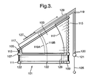
- Figures 2 and 3 show a second embodiment of a blind 101 which is similar to the blind 1 of Figure 1 and for which corresponding reference numerals (greater by 100) are used below for describing the same parts or corresponding parts.
- the blind 101 includes a fixed inclined head rail 105 and a raisable horizontally-extending bottom rail 111. Between the head rail 105 and bottom rail 111 is a middle rail 107 that is pivotable with respect to the head rail 105 about a pivot center that is adjacent to the lowermost left end of the head rail. Attached to the top, middle and bottom rails 105,107,111 are a pair of lift cords 117,119 which extend, between the rails, through perforations in a covering member 123, attached to the top, middle and bottom rails.
- the blind 101 has a vertically-movable cord collector 121 with a depending cord member 125 outside of the blind.
- Two lift cords 117,119 are attached to the cord collector 121 and are routed through, and deflected by, the head, middle and bottom rails 105,107,111 as shown in Figures 2 and 3. Both ends of one of the lift cords 117 are attached to the collector.
- the other lift cord 119 comprises two lift cord parts 119A and 119B, and one end 120 of each lift cord part is attached to the collector and the other end 122 is fixed to the bottom rail 111.
- the cord member 125 can be used to raise and lower the collector 121 to raise and lower the middle and bottom rails 107,111 and thereby retract and extend the covering member 123 as described below.
- the routing of the first lift cord 117 in the blind 101 in accordance with this invention is as follows (with reference to Figures 2 and 3).
- the first lift cord 117 extends leftwardly through the head rail 105, away from the collector 121, to a first guide in the bottom of the head rail, adjacent its left end.
- the first lift cord 117 extends downwardly from the first guide in the head rail to a first guide in the top of the middle rail 107 that is adjacent -- i.e., just to the right of -- the apex 113 of the covering material 123 in the top section 103 and adjacent the left end of the middle rail.
- the first lift cord 117 then extends rightwardly through the middle rail 107 to a second guide in the bottom of the middle rail, adjacent its right end, and then extends downwardly around an upstanding wire loop 129 attached to the top of the bottom rail 111, adjacent its right end.
- the first lift cord then extends upwardly from the wire loop 129 through a third guide in the middle rail, adjacent its right end.
- the third guide through the middle rail 107 can be adjacent -- i.e., just to the right of -- the second guide in the middle rail as shown schematically in Figures 2 and 3, but preferably, the second and third guides in the middle rail are coaxial.
- the first lift cord 117 then extends upwardly from the third guide in the middle rail adjacent to -- i.e., just to the left of -- the long side 115 of the covering material 123 in the top section 103, to a second guide in the bottom of the head rail 105, adjacent its right end.
- the first lift cord then extends rightwardly through the head rail, from its second guide, back to the collector 121.
- One lift cord part 119A extends leftwardly through the head rail 105, away from one of its end 120 and the collector 121, and at a third guide in the bottom of the head rail -- midway between the first and second guides in the head rail -- it extends downwardly to a fourth guide in the top of the middle rail 107.
- the one lift cord part 119A then extends leftwardly through the middle rail 107 to a fifth guide in the bottom of the middle rail, adjacent its left end.
- the fifth guide in the bottom of the middle rail 107 can be adjacent to -- i.e., just to the right of -- the first guide in the top of the middle rail as shown schematically in Figures 2 and 3, but preferably, the first and fifth guides in the middle rail are coaxial.
- the one lift cord part 119A then extends downwardly through the fifth guide in the middle rail and its other end 122 is attached to the top of the bottom rail 111, adjacent the left end of the bottom rail.
- the other lift cord part 119B also extends leftwardly through the head rail 105, away from one of its end 120 and the collector 121, and at a fourth guide in the bottom of the head rail - midway between the first and second guides in the head rail -- it extends downwardly to a sixth guide through the middle rail 107.
- the fourth guide in the bottom of the head rail can be adjacent to -- i.e., just to the right of -- the third guide in the bottom of the head rail as shown schematically in Figures 2 and 3, but preferably the third and fourth guides in the head rail are coaxial.
- the sixth guide in the middle rail can be adjacent to -- i.e., just to the right of -- the fourth guide in the middle rail as shown schematically in Figures 2 and 3, but preferably the fourth and sixth guides in the middle rail are also coaxial.
- the other lift cord part 119B then extends downwardly through the sixth guide in the middle rail, and its other end 122 is fixed to the top of the bottom rail, midway between the ends of the bottom rail.
- the first lift cord 117 is routed through the top section 103 of the blind 101 adjacent the apex 113 and long side 115 of the covering material 123 in the top section.
- the parts of the second lift cord 119 are routed through the top section 103 between the apex and long side 113,115 of of the covering material 123 in the top section.
- the total length of the first lift cord 117 within the top section 103 is equal to the total length of the second lift cord 119 within the top section 103 when the covering material 123 is extended.
- a spring 127 is also provided in the head rail 105, attached to a support wire 129.
- the spring 127 and support wire 129 prevent the right end of the middle rail 107 from pivoting downwardly below the left end of the middle rail.
- the cord collector 121 pulls the first and second pull cords 117,119 outwardly of the blind 101. As shown in Figure 3, this initially causes: the first pull cord 117 to pull up the wire loop 129 attached to the bottom rail 111 and thereby the right end of the bottom rail and the pull cord parts 119A, 119B to pull up the left end and middle of the the bottom rail 111 until the middle and bottom rails are vertically adjacent to one another.
- Figure 4 shows another embodiment of a blind 201 which is similar to the blind 1 of Figure 1 and for which corresponding reference numerals (greater by 200) are used below for describing the parts or corresponding parts.
- Blind 201 includes a fixed inclined head rail 205 and a raisable horizontally extending bottom rail 211. Between the head rail 205 and bottom rail 211 is a middle rail 207 that is pivotable with respect to the head rail 205 about a pivot center that is adjacent to the lowermost left end of the head rail. Attached to the top, middle and bottom rails 205, 207, 211 are a pair of lift cords 217, 219 which extend, between the rails, through perforations in a covering member 223, attached to the top, middle and bottom rails.
- the blind 201 has a vertically movable cord collector 221 with a depending cord member 225 outside of the blind.
- the two lift cords 217, 219 are attached to the cord collector 221 and are routed through, and deflected by, the head, middle and bottom rails 205, 207, 211 as shown in Figure 4.
- Both ends of both lift cords 217, 219 are attached to the collector 221.
- the cord member 225 can be used to raise and lower the collector 221 to raise and lower the middle and bottom rails 207, 211 and thereby retract and extend the covering member 223 as described below.
- the routing of the first lift cord 217 in the blind 201 in accordance with this invention is as follows (with reference to Figure 4).
- the first lift cord 217 extends rightwardly through the head rail 205, away from the collector 221, to a first guide in the bottom of the head rail adjacent its left end.
- the first lift cord 217 extends downwardly from the first guide in the head rail to a first guide in the top of the middle rail 207 that is adjacent - ie just to the right of - the apex 213 of the covering material 223 in the top section 203 and adjacent the left end of the middle rail.
- the first lift cord 217 then extends downwardly through the first guide in the middle rail to a first guide in the bottom rail 211.
- the first lift cord 217 then extends rightwardly through the bottom guide 211 to a second guide in the bottom rail 211 generally midway between opposite ends of the bottom rail 211. It then extends upwardly to a second guide in the middle rail 207 and then extends rightwardly through the middle rail 207 to a third guide in the middle rail 207, adjacent its right end.
- the first lift cord 217 then extends upwardly from the third guide in the middle rail adjacent to - ie just to the left of - the long side 215 of the covering material 223 in the top section 203, to a second guide in the head rail 205, adjacent its right end.
- the lift cord then extends leftwardly through the head rail 205, from its second guide, back to the collector 221.
- the second lift cord extends rightwardly through the head rail 205, away from its left end and the collector 221, and, at a third guide in the bottom rail 205 - midway between the first and second guides in the headrail 205 - it extends downwardly to a fourth guide in the top of the middle rail 207.
- the fourth guide in the bottom of the middle rail 207 can be adjacent to - i.e. just to the right of - the second guide in the top of the middle rail 207 as shown schematically in Figure 4, but, preferably, the second and fourth guides in the middle rail are coaxial.
- the second lift cord then extends downwardly through the fourth guide in the middle rail 207 to a third guide in the bottom rail 211, midway between the ends of the bottom rail 211.
- the third guide in the bottom rail 211 can be adjacent to - ie just to the right of - the second guide in the bottom rail 211 as shown schematically in Figure 4, but, preferably the second and third guides in the middle rail are coaxial.
- the second lift cord then extends rightwardly through the bottom rail 211 to a fourth guide in the bottom rail 211 at the right end of the bottom rail 211.
- the second lift cord 219 then extends upwardly from the fourth guide to a fifth guide in the middle 207 and then extends leftwardly through the middle 207 to a sixth guide.
- the sixth guide through the middle 207 can be adjacent ⁇ ie just to the right of - the fourth guide in the middle rail as shown schematically in Figure 4, but, preferably, the fourth and fifth guides in the middle rail are coaxial.
- the second lift cord 219 then extends upwardly from the sixth guide in the middle rail to a fourth guide in the head rail 205 midway between the first and second guides.
- the fourth guide in the head rail 205 can be adjacent - ie just to the right of - the third guide in the head rail as shown schematically in Figure 4, but, preferably, the third and fourth guides in the head rail are coaxial.
- the second lift cord 219 then extends leftwardly through the head rail, from its fourth guide, back to the collector 221.
- the total length of the first lift cord 217 within the top section 203 is equal to the total length of the second lift cord 219 within the top section 213 when the covering material 223 is extended.
- a spring 227 is also provided in the head rail 205, attached to a support wire 229.
- the spring 227 and support wire 229 prevent the right end of the middle rail 207 from pivoting downwardly below the left end of the middle 207.
- the cord collector 221 pulls the first and second pull cords 217, 219 outwardly of the blind 201. This initially causes the first pull cord to pull up the left end of the bottom rail 211 and the second pull cord to pull up the right end of the bottom rail 211 until the middle and bottom rails are vertically adjacent to one another. When the cord member 225 is pulled further downwardly, this causes the first pull cord 217 to pull up the middle rail 207 at its first and third guides, while the second pull cord pulls up the middle section of the middle rail.
- Figure 5 shows another embodiment of a blind 301 which is similar to the blind 1 of Figure 1 and for which corresponding reference numerals (greater by 300) are used below for describing the parts or corresponding parts.
- Blind 301 includes a fixed inclined head rail 305 and a raisable horizontally extending bottom rail 311. Between the head rail 305 and bottom rail 311 is a middle rail 307 that is pivotable with respect to the head rail 305 about a pivot center that is adjacent to the lowermost left end of the head rail. Attached to the top, middle and bottom rails 305, 307, 311 are a pair of lift cords 317, 319 which extend, between the rails, through perforations in a covering member 323, attached to the top, middle and bottom rails.
- the blind 301 has a vertically movable cord collector 321 with a depending cord member 325 outside of the blind.
- the two lift cords 317, 319 are attached to the cord collector 321 and are routed through, and deflected by, the head, middle and bottom rails 305, 307, 311 as shown in Figure 5.
- Both ends of both of the lift cords 317, 319 are attached to the collector 321.
- the cord member 325 can be used to raise and lower the collector 321 to raise and lower the middle and bottom rails 307, 311 and thereby retract and extend the covering member 323 as described below.
- the routing of the first lift cord 317 in the blind 301 in accordance with this invention is as follows (with reference to Figure 5).
- the first lift cord 317 extends leftwardly through the headrail 305 away from the collector 321 to a first guide in the bottom of the headrail, adjacent its left end.
- the first lift cord 317 extends downwardly from the first guide in the head rail to a first guide in the top of the middle rail 307 that is adjacent - ie just to the right of - the apex 313 of the covering material 323 in the top section 303 and adjacent the left end of the middle rail.
- the first lift cord 317 then extends rightwardly through the middle 307 to a second guide in the bottom of the middle rail, partway across, for instance one third, and then extends downwardly to a first guide in the top of the bottom rail 311, again partway along, for instance a third, the length of the bottom rail 311.
- the first lift cord 317 then extends along the bottom rail 311 to a second guide in the bottom rail, adjacent its right end.
- the first lift cord 317 then extends upwardly from the second guide in the bottom rail up to a third guide in the middle rail 307, adjacent its right end.
- the first lift cord 317 then extends upwardly to a second guide in the head rail 305 towards its right end.
- the first lift cord then extends leftwardly through the head rail, from its second guide, back to the collector 321.
- the second lift cord 319 extends rightwardly through the head rail 305, away from the collector 321, to a third guide in the bottom of the head rail 305, partway, for instance a third, along the head rail 305.
- the second lift cord 319 then extends downwardly to a fourth guide in the top of the middle rail 307 again partway, for instance a third, along the middle rail 307.
- the fourth guide of the middle rail 307 may be adjacent to the second guide of the middle 307, but, preferably coaxially above the second guide as illustrated schematically in Figure 5.
- the second lift cord 319 then extends leftwardly through the middle 307 to a fifth guide in the bottom of the middle rail adjacent its left end.
- the fifth guide in the middle rail 307 may be adjacent to the first guide in the middle rail, but, preferably, is coaxially below the first guide as illustrated schematically in Figure 5.
- the second lift cord 319 then extends downwardly from the fifth guide in the middle rail 307 to a third guide in the bottom rail 311 immediately adjacent to the left end of the bottom rail 311.
- the second lift cord 319 then extends rightwardly through the bottom rail 311 to a fourth guide partway, for instance two thirds, along the bottom rail 311.
- the second lift cord 319 then extends upwardly from the fourth guide in the bottom rail 311 to a seventh guide in the middle rail 307 partway, for instance two thirds, along the middle rail 307 from the left end and the apex 313.
- the second lift cord 319 then extends upwardly from the seventh guide in the middle rail to a fourth guide in the bottom of the headrail 305 partway, for instance two thirds, along its length from the left end.
- the second lift cord then extends leftwardly through the headrail, from its fourth guide, back to the collector 321.
- the total length of the first lift cord 319 within the top section 303 is equal to the total length of the second lift cord 319 within the top section 303 when the covering material 323 is extended.
- a spring 327 is also provided in the headrail 305, attached to a support wire 329.
- the spring 327 and support wire 329 prevent the right end of the middle rail 307 from pivoting downwardly below the left end of the middle rail 307.
- the cord collector 321 pulls the first and second pull cords 317, 319 outwardly of the blind 301. This initially causes the first pull cord 317 to pull up the bottom rail 311 towards the right hand end and the second pull cord 319 to pull up the left hand end until the middle and bottom rails are vertically adjacent to one another. When the cord member 325 is pulled further downwardly, this causes the first pull cord to pull up the middle rail 307 at its third guide and to pull up further the bottom rail 311 while the second cord 319 pulls up the middle portion of the middle rail 307.
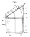
- Figure 6 shows another embodiment of a blind 401 which is similar to the blind 1 of Figure 1 and for which corresponding reference numerals (greater by 400) are used below for describing the parts or corresponding parts.
- Blind 401 includes a fixed inclined head rail 405 and a raisable horizontally extending bottom rail 411. Between the head rail 405 and bottom rail 411 is a middle rail 407 that is pivotable with respect to the head rail 405 about a pivot center that is adjacent to the lowermost left end of the head rail. Attached to the top, middle and bottom rails 405, 407, 411 are a pair of lift cords 417, 419 which extend, between the rails, through perforations in a covering member 423, attached to the top, middle and bottom rails.
- the blind 401 has a vertically movable cord collector 421 with a depending cord member 425 outside of the blind.
- the two lift cords 417, 419 are attached to the cord collector 421 and are routed through, and deflected by, the head, middle and bottom rails 405, 407, 411 as shown in Figure 6.
- Both ends of both lift cords 417, 419 are attached to the collector 421.
- the cord member 425 can be used to raise and lower the collector 421 to raise and lower the middle and bottom rails 407, 411 and thereby retract and extend the covering member 423 as described below.
- the routing of the first lift cord 417 in the blind 401 in accordance with this invention is as follows (with reference to Figure 6).
- the first lift cord 417 extends rightwardly through the head rail 405 away from the collector 421 to a first guide in the head rail, adjacent its left end.
- the first lift cord 417 extends downwardly from the first guide in the head rail to a first guide in the top of the middle rail 407 that is adjacent - i.e. just to the right of - the apex 413 of the covering material 423 in the top section 403 and adjacent the left end of the middle rail.
- the first lift cord 417 then extends rightwardly through the middle rail 407 to a second guide in the bottom of the middle rail generally at the center of middle rail 407.
- the first lift cord 417 then extends downwardly to a first guide of the bottom rail 411 positioned generally half way along the bottom rail 411.
- the first lift cord 417 then extends along the bottom rail 411 to a second guide at the right end of the bottom rail 411 and, from the second guide, extends upwardly to a third guide of the middle rail 407.
- the first lift cord 417 then extends upwardly from the third guide in the middle rail adjacent to - i.e. just to the left of - the long side 415 of the covering material 423 in the top section 403, to a second guide in the bottom of the head rail 405 adjacent its right end.
- the first lift cord then extends leftwardly through the head rail, from its second guide, back to the collector 421.
- the second lift cord 419 extends rightwardly through the head rail 405, away from the collector 421, to a third guide in the bottom of the head rail 405 at a position generally half way along the head rail 405.
- the second lift cord 419 extends downwardly from the third guide in the head rail to a fourth guide in the top of the middle rail 407.
- the fourth guide of the middle rail 407 may be adjacent to the second guide of the middle rail 407, but, preferably, the fourth guide is position coaxially above the second guide as illustrated schematically in Figure 6.
- the second lift cord 417 then extends leftwardly through the middle rail 407 to a fifth guide in the bottom of the middle rail 407 and adjacent its left end.
- the fifth guide may be adjacent the first guide, but, preferably, is positioned coaxially below the first guide as illustrated schematically in Figure 6.
- the second lift cord then extends downwardly from the fifth guide of the middle rail 407 to a third guide of the bottom rail 411 at the left end of the bottom rail 411.
- the second lift cord 417 then extends rightwardly through the bottom rail 411 to a fourth guide in the bottom rail 411.
- the fourth guide through the bottom rail 411 can be adjacent - i.e. just to the right of - the first guide in the bottom rail 411 as shown schematically in Figure 6, but, preferably, the first and fourth guides in the bottom rail are coaxial.
- the second lift cord 419 then extends upwardly from the fourth guide to a sixth guide in the middle rail 407.
- the sixth guide through the middle rail 407 can be adjacent - i.e. just to the right of - the second and fourth guides in the middle rail as shown schematically in Figure 6, but, preferably, the sixth guide is coaxial with the second and fourth guides.
- the second lift cord 417 continues upwardly to a fourth guide in the head rail 405.
- the fourth guide through the head rail 405 can be adjacent - i.e. just to the right of - the third guide in the head rail as shown schematically in Figure 6, but, preferably, the third and fourth guides in the head rail are coaxial.
- the second lift cord then extends leftwardly through the head rail 405, from its fourth guide, back to the collector 421.
- the total length of the first lift cord 417 within the top section 403 is equal to the total length of the second lift cord 419 within the top section 403 when the covering material 423 is extended.
- a spring 427 is also provided in the head rail 405, attached to a support wire 429.
- the spring 427 and support wire 429 prevent the right end of the middle rail 407 from pivoting downwardly below the left end of the middle rail.
- the cord collector 421 pulls the first and second pull cords 417, 419 outwardly of the blind 401. This initially causes the first pull cord 417 to pull up the right-hand section of the bottom rail 411 and the second pull cord 419 to pull up the left-hand section of the bottom rail 411.
- the cord member 425 is pulled further downwardly, this causes the first pull cord 417 to pull up the middle rail 407 at its first and third guides and to pull up further the bottom rail 411 while the second pull cord pulls up further the left end and middle of the bottom rail 411 so that both the middle and bottom rails pivot about the pivot center of the middle rail.
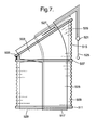
- Figure 7 shows another embodiment of a blind 501 which is similar to the blind 1 of Figure 1 and for which corresponding reference numerals (greater by 500) are used below for describing the parts or corresponding parts.
- Blind 501 includes a fixed inclined head rail 505 and a raisable horizontally extending bottom rail 511. Between the head rail 505 and bottom rail 511 is a middle rail 507 that is pivotable with respect to the head rail 505 about a pivot center that is adjacent to the lowermost left end of the head rail. Attached to the top, middle and bottom rails 505, 507, 511 are a pair of lift cords 517, 519 which extend, between the rails, through perforations in a covering member 523, attached to the top, middle and bottom rails.
- the blind 501 has a vertically movable cord collector 521 with a depending cord member 525 outside of the blind.
- the two lift cords 517, 519 are attached to the cord collector 521 and are routed through, and deflected by, the head, middle and bottom rails 505, 507, 511 as shown in Figure 7.
- first and second lift cords 517, 519 within the blind itself is identical to the embodiment of Figure 6.
- the collector 521 and cord member 525 are positioned on the right side of the blind 501, ie just to the right of the long side 515 of the covering material 523 in the top section 503.
- the first and second lift cords 517, 519 therefore run in an opposite direction (in terms of left and right) from the collector 521.
- cord collector and the cord member 525 can be repositioned in this way for any embodiment.
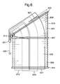
- Figure 8 shows another embodiment of a blind 601 which is similar to the blind 1 of Figure 1 and for which corresponding reference numerals (greater by 600) are used below for describing the same parts of corresponding parts.
- the blind differs most significantly from the blind 1 of Figure 1 by having three, rather than two lift cords.
- the blind 601 includes a fixed inclined head rail 605 and a raisable horizontally extending bottom rail 611. Between the head rail 605 and bottom rail 611 is a middle rail 607 that is pivotable with respect to the head rail 605 about a pivot center that is adjacent to the lowermost left end of the head rail. Attached to the top, middle and bottom rails 605, 607, 611 are three lift cords 617, 618 and 619 which extend between the rails through perforations in a covering member 623 attached to the top, middle and bottom rails.
- the blind 601 has a vertically movable cord collector 621 with a depending cord member 625 outside of the blind.
- Three lift cords 617, 618, 619 are attached to the cord collector 621 and are routed through, and deflected by, the head, middle and bottom rails 605, 607, 611 as shown in Figure 8. Both ends of all three lift cords 617, 618, 619 are attached to the collector 621.
- the cord member 625 can be used to raise and lower the collector 621 to raise and lower the middle and bottom rails 607, 611 and thereby retract and extend the covering member 623 as described below.
- Figure 8 is identical to that of Figure 6 other than the addition of the third lift cord 618.
- the routing of the first lift cord 617 and second lift cord 619 is the same as was described for the first lift cord 417 and second lift cord 419 of Figure 6. Hence, this description will not be repeated here.
- the routing of the third lift cord 618 in the blind 608 in accordance with this invention is as follows (with reference to Figure 8).
- the third lift cord 618 extends leftwardly through the head rail 605, away from the collector 621, to a fifth guide in the bottom of the head rail someway, for instance a quarter of the way, from the left end of the head rail 605.
- the third lift cord 618 extends downwardly from the fifth guide in the head rail to a seventh guide in the top of the middle rail 607 that similarly is someway, for instance a quarter of the way, from the left end of the middle rail 607 and, hence, the apex 613 of the covering material 623.
- the third lift cord 618 then extends downwardly from the seventh guide of the middle rail 607 to a fifth guide of the bottom rail 611.
- the fifth guide of the bottom rail 611 is positioned someway, for instance a quarter of the way, from the left end of the bottom rail 611.
- the third lift cord 618 then extends rightwardly through the bottom rail 611 to a sixth guide in the bottom rail 611 which is someway, for instance three quarters of the way, from the left end of the bottom rail 611.
- the third lift cord 618 then extends upwardly to an eighth guide in the middle rail 607 again someway, for instance three quarters of the way, from the left end of the middle rail 607.
- the third lift cord 618 extends through the eighth guide of the middle rail 607 and then upwardly to a sixth guide of the head rail 605 which, again, is someway, for instance three quarters of the way, from the left end of the head rail 605.
- the third lift cord then extends leftwardly through the head rail, from its fifth guide, back to the collector 621.
- the total length of the third lift cord 618 within the top section 603 is equal to the total length of the first lift cord 617 within the top section 103 and also to the total length of the second lift cord 619 within the top section 603 when the covering material 623 is extended.
- the positioning of the fifth and sixth guides in the head rail 605 and the seventh and eighth guides in the middle rail 607 and the fifth and sixth guides in the bottom rail 611 can be varied in any way, provided that this condition is met.
- the cord collector 621 pulls the first, second and third pull cords 617, 619, 618 outwardly of the blind.
- the first and second pull cords 617 and 619 operate as described for Figure 6.
- the third pull cord 619 initially pulls up the bottom rail 611 at mid-sections along its length and then causes the middle and bottom rails to pivot about the pivot center of the middle rail.
- third or further cords could be added to any of the embodiments.
- Third or further cords help provide a more evenly distributed lifting and rotating force on the bottom and middle rails.
- the blind covering material 23,123 need not be a pleated blind material but can be any flexible material sheet member that is foldable, pleatable or rollable.
- the blind covering material can also be formed as a collapsible slatted blind in which the vanes or slats may be pivotally adjustable for additional light regulation.
- the movable middle rail 7,107 and bottom rail 11,111 can be either directly or indirectly attached to the covering material 23,123 in the top section 3,103 and bottom section 9, 109 of the blind 1,101 in order to extend and retract the top and bottom sections.
Landscapes
- Engineering & Computer Science (AREA)
- Structural Engineering (AREA)
- Architecture (AREA)
- Civil Engineering (AREA)
- Blinds (AREA)
- Lock And Its Accessories (AREA)
- Lubricants (AREA)
- Characterised By The Charging Evacuation (AREA)
- Fittings On The Vehicle Exterior For Carrying Loads, And Devices For Holding Or Mounting Articles (AREA)
Priority Applications (1)
| Application Number | Priority Date | Filing Date | Title |
|---|---|---|---|
| EP05250089A EP1555382B1 (de) | 2004-01-13 | 2005-01-11 | Zurückziehbare Jalousie |
Applications Claiming Priority (3)
| Application Number | Priority Date | Filing Date | Title |
|---|---|---|---|
| EP04075018 | 2004-01-13 | ||
| EP04075018 | 2004-01-13 | ||
| EP05250089A EP1555382B1 (de) | 2004-01-13 | 2005-01-11 | Zurückziehbare Jalousie |
Publications (2)
| Publication Number | Publication Date |
|---|---|
| EP1555382A1 true EP1555382A1 (de) | 2005-07-20 |
| EP1555382B1 EP1555382B1 (de) | 2007-08-22 |
Family
ID=34717282
Family Applications (1)
| Application Number | Title | Priority Date | Filing Date |
|---|---|---|---|
| EP05250089A Expired - Lifetime EP1555382B1 (de) | 2004-01-13 | 2005-01-11 | Zurückziehbare Jalousie |
Country Status (6)
| Country | Link |
|---|---|
| US (1) | US7261137B2 (de) |
| EP (1) | EP1555382B1 (de) |
| AT (1) | ATE371083T1 (de) |
| DE (1) | DE602005002055T2 (de) |
| DK (1) | DK1555382T3 (de) |
| ES (1) | ES2289661T3 (de) |
Families Citing this family (8)
| Publication number | Priority date | Publication date | Assignee | Title |
|---|---|---|---|---|
| EP1837478A1 (de) * | 2004-12-28 | 2007-09-26 | Seiki Hanbai Co., Ltd. | Abschirmvorrichtung |
| US7509989B2 (en) * | 2005-12-05 | 2009-03-31 | Dung Viet Pham | Window blind system |
| WO2016040646A1 (en) | 2014-09-10 | 2016-03-17 | Hunter Douglas Inc. | Roll-up coverings for architectural openings and related methods, systems and devices |
| US9982481B2 (en) * | 2015-11-25 | 2018-05-29 | Mario M Marocco | Arch window covering with control |
| US10934772B2 (en) | 2018-02-19 | 2021-03-02 | Tucson Rolling Shutters, Inc. | Self-adjusting bottom bar for a retractable screen |
| US11585151B2 (en) | 2018-02-19 | 2023-02-21 | Tucson Rolling Shutters, Inc. | Self-adjusting bottom bar for a retractable screen |
| IT202100009542A1 (it) * | 2021-04-15 | 2022-10-15 | Lci Italy Srl | Dispositivo di oscuramento di un finestrino di un veicolo |
| GB202201279D0 (en) | 2022-02-01 | 2022-03-16 | Hunter Douglas Ind Bv | Blind |
Citations (4)
| Publication number | Priority date | Publication date | Assignee | Title |
|---|---|---|---|---|
| US5092383A (en) * | 1987-04-01 | 1992-03-03 | Bw-Usa, Inc. | Shade for non-rectangular opening |
| EP0532036A2 (de) * | 1991-09-13 | 1993-03-17 | KARL H. BLÖCKER GmbH & Co. | Faltenvorhang für eine trapezförmige Fläche |
| EP0674091A2 (de) * | 1994-03-08 | 1995-09-27 | Schön B.V. | Zurückziehbare Store oder Jalousie |
| EP1120534A1 (de) * | 2000-01-27 | 2001-08-01 | KARL H. BLÖCKER GmbH & Co. | Vorhanganlage mit mindestens zwei beweglichen Schienen |
Family Cites Families (2)
| Publication number | Priority date | Publication date | Assignee | Title |
|---|---|---|---|---|
| US3646986A (en) * | 1970-05-15 | 1972-03-07 | Levolor Lorentzen Inc | Inclined-soffit venetian blind and installation |
| US4518025A (en) * | 1983-11-10 | 1985-05-21 | Verosol Usa Inc. | Sun blind construction |
-
2005
- 2005-01-11 AT AT05250089T patent/ATE371083T1/de active
- 2005-01-11 DE DE602005002055T patent/DE602005002055T2/de not_active Expired - Lifetime
- 2005-01-11 ES ES05250089T patent/ES2289661T3/es not_active Expired - Lifetime
- 2005-01-11 DK DK05250089T patent/DK1555382T3/da active
- 2005-01-11 EP EP05250089A patent/EP1555382B1/de not_active Expired - Lifetime
- 2005-01-12 US US11/035,355 patent/US7261137B2/en not_active Expired - Lifetime
Patent Citations (4)
| Publication number | Priority date | Publication date | Assignee | Title |
|---|---|---|---|---|
| US5092383A (en) * | 1987-04-01 | 1992-03-03 | Bw-Usa, Inc. | Shade for non-rectangular opening |
| EP0532036A2 (de) * | 1991-09-13 | 1993-03-17 | KARL H. BLÖCKER GmbH & Co. | Faltenvorhang für eine trapezförmige Fläche |
| EP0674091A2 (de) * | 1994-03-08 | 1995-09-27 | Schön B.V. | Zurückziehbare Store oder Jalousie |
| EP1120534A1 (de) * | 2000-01-27 | 2001-08-01 | KARL H. BLÖCKER GmbH & Co. | Vorhanganlage mit mindestens zwei beweglichen Schienen |
Also Published As
| Publication number | Publication date |
|---|---|
| DK1555382T3 (da) | 2007-12-27 |
| DE602005002055T2 (de) | 2008-05-15 |
| DE602005002055D1 (de) | 2007-10-04 |
| EP1555382B1 (de) | 2007-08-22 |
| ATE371083T1 (de) | 2007-09-15 |
| US7261137B2 (en) | 2007-08-28 |
| US20050150607A1 (en) | 2005-07-14 |
| ES2289661T3 (es) | 2008-02-01 |
Similar Documents
| Publication | Publication Date | Title |
|---|---|---|
| US20060048904A1 (en) | Dual drop covering for architectural openings | |
| JP4585993B2 (ja) | 巻上げブラインドセグメントを有する窓覆い | |
| EP2131008A2 (de) | Fensterabdeckung | |
| CN1542254A (zh) | 罗马帘 | |
| US20070175593A1 (en) | Roman shade with folding sheets | |
| US5860464A (en) | Retractable blind or shade assembly | |
| JP2007500296A (ja) | ウィンドウカバー | |
| US20050155720A1 (en) | Roman shade capable of adjusting light transmittance | |
| EP3080378B1 (de) | Jalousie | |
| EP1555382B1 (de) | Zurückziehbare Jalousie | |
| EP2149667B1 (de) | Fensterabdeckung mit mindestens einem verformbaren Anschluss | |
| US20180094480A1 (en) | Stiffened pull cord for architectural coverings | |
| CN1828003B (zh) | 百叶帘 | |
| JP3697688B2 (ja) | 日射遮蔽装置 | |
| EP1744005A1 (de) | Fensterabdeckung mit faltbarer Verdunkelungsanordnungen | |
| JP3660845B2 (ja) | ローマンシェード | |
| EP0513468A1 (de) | Fensterabdeckvorrichtung | |
| GB2455718A (en) | Window blind | |
| EP4219877A1 (de) | Einziehbare jalousieanordnung | |
| JP7434857B2 (ja) | ブラインド | |
| JPH0211598Y2 (de) | ||
| EP1512826B1 (de) | Endstück für einen Vorhang mit einer geneigten Seitenkante | |
| CN2566761Y (zh) | 收折伸缩式窗帘 | |
| EP3159472B1 (de) | Vertikal faltbare tür | |
| CN2851472Y (zh) | 可左右移动开合的百叶窗帘 |
Legal Events
| Date | Code | Title | Description |
|---|---|---|---|
| PUAI | Public reference made under article 153(3) epc to a published international application that has entered the european phase |
Free format text: ORIGINAL CODE: 0009012 |
|
| AK | Designated contracting states |
Kind code of ref document: A1 Designated state(s): AT BE BG CH CY CZ DE DK EE ES FI FR GB GR HU IE IS IT LI LT LU MC NL PL PT RO SE SI SK TR |
|
| AX | Request for extension of the european patent |
Extension state: AL BA HR LV MK YU |
|
| 17P | Request for examination filed |
Effective date: 20051201 |
|
| AKX | Designation fees paid |
Designated state(s): AT BE BG CH CY CZ DE DK EE ES FI FR GB GR HU IE IS IT LI LT LU MC NL PL PT RO SE SI SK TR |
|
| GRAP | Despatch of communication of intention to grant a patent |
Free format text: ORIGINAL CODE: EPIDOSNIGR1 |
|
| GRAS | Grant fee paid |
Free format text: ORIGINAL CODE: EPIDOSNIGR3 |
|
| GRAA | (expected) grant |
Free format text: ORIGINAL CODE: 0009210 |
|
| AK | Designated contracting states |
Kind code of ref document: B1 Designated state(s): AT BE BG CH CY CZ DE DK EE ES FI FR GB GR HU IE IS IT LI LT LU MC NL PL PT RO SE SI SK TR |
|
| REG | Reference to a national code |
Ref country code: GB Ref legal event code: FG4D |
|
| REG | Reference to a national code |
Ref country code: CH Ref legal event code: EP |
|
| REG | Reference to a national code |
Ref country code: IE Ref legal event code: FG4D |
|
| REF | Corresponds to: |
Ref document number: 602005002055 Country of ref document: DE Date of ref document: 20071004 Kind code of ref document: P |
|
| REG | Reference to a national code |
Ref country code: CH Ref legal event code: NV Representative=s name: ROTTMANN, ZIMMERMANN + PARTNER AG |
|
| REG | Reference to a national code |
Ref country code: SE Ref legal event code: TRGR |
|
| REG | Reference to a national code |
Ref country code: DK Ref legal event code: T3 |
|
| PG25 | Lapsed in a contracting state [announced via postgrant information from national office to epo] |
Ref country code: LT Free format text: LAPSE BECAUSE OF FAILURE TO SUBMIT A TRANSLATION OF THE DESCRIPTION OR TO PAY THE FEE WITHIN THE PRESCRIBED TIME-LIMIT Effective date: 20070822 Ref country code: IS Free format text: LAPSE BECAUSE OF FAILURE TO SUBMIT A TRANSLATION OF THE DESCRIPTION OR TO PAY THE FEE WITHIN THE PRESCRIBED TIME-LIMIT Effective date: 20071222 Ref country code: BG Free format text: LAPSE BECAUSE OF FAILURE TO SUBMIT A TRANSLATION OF THE DESCRIPTION OR TO PAY THE FEE WITHIN THE PRESCRIBED TIME-LIMIT Effective date: 20071122 Ref country code: FI Free format text: LAPSE BECAUSE OF FAILURE TO SUBMIT A TRANSLATION OF THE DESCRIPTION OR TO PAY THE FEE WITHIN THE PRESCRIBED TIME-LIMIT Effective date: 20070822 |
|
| REG | Reference to a national code |
Ref country code: ES Ref legal event code: FG2A Ref document number: 2289661 Country of ref document: ES Kind code of ref document: T3 |
|
| PG25 | Lapsed in a contracting state [announced via postgrant information from national office to epo] |
Ref country code: PL Free format text: LAPSE BECAUSE OF FAILURE TO SUBMIT A TRANSLATION OF THE DESCRIPTION OR TO PAY THE FEE WITHIN THE PRESCRIBED TIME-LIMIT Effective date: 20070822 |
|
| PG25 | Lapsed in a contracting state [announced via postgrant information from national office to epo] |
Ref country code: GR Free format text: LAPSE BECAUSE OF FAILURE TO SUBMIT A TRANSLATION OF THE DESCRIPTION OR TO PAY THE FEE WITHIN THE PRESCRIBED TIME-LIMIT Effective date: 20071123 |
|
| PG25 | Lapsed in a contracting state [announced via postgrant information from national office to epo] |
Ref country code: SK Free format text: LAPSE BECAUSE OF FAILURE TO SUBMIT A TRANSLATION OF THE DESCRIPTION OR TO PAY THE FEE WITHIN THE PRESCRIBED TIME-LIMIT Effective date: 20070822 Ref country code: CZ Free format text: LAPSE BECAUSE OF FAILURE TO SUBMIT A TRANSLATION OF THE DESCRIPTION OR TO PAY THE FEE WITHIN THE PRESCRIBED TIME-LIMIT Effective date: 20070822 Ref country code: PT Free format text: LAPSE BECAUSE OF FAILURE TO SUBMIT A TRANSLATION OF THE DESCRIPTION OR TO PAY THE FEE WITHIN THE PRESCRIBED TIME-LIMIT Effective date: 20080122 |
|
| PLBE | No opposition filed within time limit |
Free format text: ORIGINAL CODE: 0009261 |
|
| STAA | Information on the status of an ep patent application or granted ep patent |
Free format text: STATUS: NO OPPOSITION FILED WITHIN TIME LIMIT |
|
| PG25 | Lapsed in a contracting state [announced via postgrant information from national office to epo] |
Ref country code: RO Free format text: LAPSE BECAUSE OF FAILURE TO SUBMIT A TRANSLATION OF THE DESCRIPTION OR TO PAY THE FEE WITHIN THE PRESCRIBED TIME-LIMIT Effective date: 20070822 |
|
| 26N | No opposition filed |
Effective date: 20080526 |
|
| PG25 | Lapsed in a contracting state [announced via postgrant information from national office to epo] |
Ref country code: MC Free format text: LAPSE BECAUSE OF NON-PAYMENT OF DUE FEES Effective date: 20080131 |
|
| PG25 | Lapsed in a contracting state [announced via postgrant information from national office to epo] |
Ref country code: IE Free format text: LAPSE BECAUSE OF NON-PAYMENT OF DUE FEES Effective date: 20080111 Ref country code: EE Free format text: LAPSE BECAUSE OF FAILURE TO SUBMIT A TRANSLATION OF THE DESCRIPTION OR TO PAY THE FEE WITHIN THE PRESCRIBED TIME-LIMIT Effective date: 20070822 |
|
| PG25 | Lapsed in a contracting state [announced via postgrant information from national office to epo] |
Ref country code: SI Free format text: LAPSE BECAUSE OF FAILURE TO SUBMIT A TRANSLATION OF THE DESCRIPTION OR TO PAY THE FEE WITHIN THE PRESCRIBED TIME-LIMIT Effective date: 20070822 |
|
| PG25 | Lapsed in a contracting state [announced via postgrant information from national office to epo] |
Ref country code: CY Free format text: LAPSE BECAUSE OF FAILURE TO SUBMIT A TRANSLATION OF THE DESCRIPTION OR TO PAY THE FEE WITHIN THE PRESCRIBED TIME-LIMIT Effective date: 20070822 |
|
| PG25 | Lapsed in a contracting state [announced via postgrant information from national office to epo] |
Ref country code: HU Free format text: LAPSE BECAUSE OF FAILURE TO SUBMIT A TRANSLATION OF THE DESCRIPTION OR TO PAY THE FEE WITHIN THE PRESCRIBED TIME-LIMIT Effective date: 20080223 Ref country code: LU Free format text: LAPSE BECAUSE OF NON-PAYMENT OF DUE FEES Effective date: 20080111 |
|
| PG25 | Lapsed in a contracting state [announced via postgrant information from national office to epo] |
Ref country code: TR Free format text: LAPSE BECAUSE OF FAILURE TO SUBMIT A TRANSLATION OF THE DESCRIPTION OR TO PAY THE FEE WITHIN THE PRESCRIBED TIME-LIMIT Effective date: 20070822 |
|
| REG | Reference to a national code |
Ref country code: CH Ref legal event code: PFA Owner name: HUNTER DOUGLAS INDUSTRIES B.V. Free format text: HUNTER DOUGLAS INDUSTRIES B.V.#PIEKSTRAAT 2#3071 EL ROTTERDAM (NL) -TRANSFER TO- HUNTER DOUGLAS INDUSTRIES B.V.#PIEKSTRAAT 2#3071 EL ROTTERDAM (NL) |
|
| REG | Reference to a national code |
Ref country code: FR Ref legal event code: PLFP Year of fee payment: 12 |
|
| REG | Reference to a national code |
Ref country code: CH Ref legal event code: PCAR Free format text: NEW ADDRESS: GARTENSTRASSE 28 A, 5400 BADEN (CH) |
|
| REG | Reference to a national code |
Ref country code: FR Ref legal event code: PLFP Year of fee payment: 13 |
|
| REG | Reference to a national code |
Ref country code: FR Ref legal event code: PLFP Year of fee payment: 14 |
|
| P01 | Opt-out of the competence of the unified patent court (upc) registered |
Effective date: 20230331 |
|
| PGFP | Annual fee paid to national office [announced via postgrant information from national office to epo] |
Ref country code: GB Payment date: 20231130 Year of fee payment: 20 |
|
| PGFP | Annual fee paid to national office [announced via postgrant information from national office to epo] |
Ref country code: SE Payment date: 20231213 Year of fee payment: 20 Ref country code: NL Payment date: 20231215 Year of fee payment: 20 Ref country code: FR Payment date: 20231212 Year of fee payment: 20 |
|
| PGFP | Annual fee paid to national office [announced via postgrant information from national office to epo] |
Ref country code: BE Payment date: 20231219 Year of fee payment: 20 |
|
| PGFP | Annual fee paid to national office [announced via postgrant information from national office to epo] |
Ref country code: ES Payment date: 20240205 Year of fee payment: 20 |
|
| PGFP | Annual fee paid to national office [announced via postgrant information from national office to epo] |
Ref country code: AT Payment date: 20231227 Year of fee payment: 20 |
|
| PGFP | Annual fee paid to national office [announced via postgrant information from national office to epo] |
Ref country code: DE Payment date: 20231128 Year of fee payment: 20 Ref country code: CH Payment date: 20240202 Year of fee payment: 20 |
|
| PGFP | Annual fee paid to national office [announced via postgrant information from national office to epo] |
Ref country code: IT Payment date: 20231212 Year of fee payment: 20 Ref country code: DK Payment date: 20240111 Year of fee payment: 20 |
|
| REG | Reference to a national code |
Ref country code: DE Ref legal event code: R071 Ref document number: 602005002055 Country of ref document: DE |
|
| REG | Reference to a national code |
Ref country code: DK Ref legal event code: EUP Expiry date: 20250111 |
|
| REG | Reference to a national code |
Ref country code: CH Ref legal event code: PL Ref country code: NL Ref legal event code: MK Effective date: 20250110 |
|
| REG | Reference to a national code |
Ref country code: ES Ref legal event code: FD2A Effective date: 20250124 |
|
| REG | Reference to a national code |
Ref country code: GB Ref legal event code: PE20 Expiry date: 20250110 |
|
| REG | Reference to a national code |
Ref country code: AT Ref legal event code: MK07 Ref document number: 371083 Country of ref document: AT Kind code of ref document: T Effective date: 20250111 |
|
| REG | Reference to a national code |
Ref country code: BE Ref legal event code: MK Effective date: 20250111 |
|
| REG | Reference to a national code |
Ref country code: SE Ref legal event code: EUG |
|
| PG25 | Lapsed in a contracting state [announced via postgrant information from national office to epo] |
Ref country code: ES Free format text: LAPSE BECAUSE OF EXPIRATION OF PROTECTION Effective date: 20250112 |
|
| PG25 | Lapsed in a contracting state [announced via postgrant information from national office to epo] |
Ref country code: GB Free format text: LAPSE BECAUSE OF EXPIRATION OF PROTECTION Effective date: 20250110 |