EP0674101B1 - Steuerung für Brennkraftmaschine - Google Patents
Steuerung für Brennkraftmaschine Download PDFInfo
- Publication number
- EP0674101B1 EP0674101B1 EP95200455A EP95200455A EP0674101B1 EP 0674101 B1 EP0674101 B1 EP 0674101B1 EP 95200455 A EP95200455 A EP 95200455A EP 95200455 A EP95200455 A EP 95200455A EP 0674101 B1 EP0674101 B1 EP 0674101B1
- Authority
- EP
- European Patent Office
- Prior art keywords
- engine
- inlet air
- air rate
- map
- value
- Prior art date
- Legal status (The legal status is an assumption and is not a legal conclusion. Google has not performed a legal analysis and makes no representation as to the accuracy of the status listed.)
- Expired - Lifetime
Links
- 238000002485 combustion reaction Methods 0.000 title claims description 8
- 238000012937 correction Methods 0.000 claims description 40
- 238000000034 method Methods 0.000 claims description 22
- 230000008859 change Effects 0.000 claims description 2
- 238000005259 measurement Methods 0.000 description 28
- 239000000446 fuel Substances 0.000 description 15
- 238000013459 approach Methods 0.000 description 12
- 230000000694 effects Effects 0.000 description 10
- 230000008569 process Effects 0.000 description 7
- 230000004044 response Effects 0.000 description 6
- 230000008901 benefit Effects 0.000 description 4
- 238000010790 dilution Methods 0.000 description 3
- 239000012895 dilution Substances 0.000 description 3
- 230000009467 reduction Effects 0.000 description 3
- 230000003197 catalytic effect Effects 0.000 description 2
- 238000010586 diagram Methods 0.000 description 2
- 238000001914 filtration Methods 0.000 description 2
- 230000006870 function Effects 0.000 description 2
- 238000002347 injection Methods 0.000 description 2
- 239000007924 injection Substances 0.000 description 2
- 230000000704 physical effect Effects 0.000 description 2
- 230000001052 transient effect Effects 0.000 description 2
- 239000000470 constituent Substances 0.000 description 1
- 238000011217 control strategy Methods 0.000 description 1
- 230000003247 decreasing effect Effects 0.000 description 1
- 238000001739 density measurement Methods 0.000 description 1
- 230000008014 freezing Effects 0.000 description 1
- 238000007710 freezing Methods 0.000 description 1
Images

Classifications
-
- F—MECHANICAL ENGINEERING; LIGHTING; HEATING; WEAPONS; BLASTING
- F02—COMBUSTION ENGINES; HOT-GAS OR COMBUSTION-PRODUCT ENGINE PLANTS
- F02D—CONTROLLING COMBUSTION ENGINES
- F02D41/00—Electrical control of supply of combustible mixture or its constituents
- F02D41/02—Circuit arrangements for generating control signals
- F02D41/18—Circuit arrangements for generating control signals by measuring intake air flow
-
- F—MECHANICAL ENGINEERING; LIGHTING; HEATING; WEAPONS; BLASTING
- F02—COMBUSTION ENGINES; HOT-GAS OR COMBUSTION-PRODUCT ENGINE PLANTS
- F02D—CONTROLLING COMBUSTION ENGINES
- F02D41/00—Electrical control of supply of combustible mixture or its constituents
- F02D41/30—Controlling fuel injection
- F02D41/32—Controlling fuel injection of the low pressure type
-
- F—MECHANICAL ENGINEERING; LIGHTING; HEATING; WEAPONS; BLASTING
- F02—COMBUSTION ENGINES; HOT-GAS OR COMBUSTION-PRODUCT ENGINE PLANTS
- F02D—CONTROLLING COMBUSTION ENGINES
- F02D2200/00—Input parameters for engine control
- F02D2200/02—Input parameters for engine control the parameters being related to the engine
- F02D2200/04—Engine intake system parameters
- F02D2200/0402—Engine intake system parameters the parameter being determined by using a model of the engine intake or its components
-
- F—MECHANICAL ENGINEERING; LIGHTING; HEATING; WEAPONS; BLASTING
- F02—COMBUSTION ENGINES; HOT-GAS OR COMBUSTION-PRODUCT ENGINE PLANTS
- F02D—CONTROLLING COMBUSTION ENGINES
- F02D2200/00—Input parameters for engine control
- F02D2200/02—Input parameters for engine control the parameters being related to the engine
- F02D2200/04—Engine intake system parameters
- F02D2200/0411—Volumetric efficiency
Definitions
- This invention relates to internal combustion engine control and, more specifically, to a method associated with engine cylinder inlet air rate.
- Internal combustion engine air/fuel ratio control is known in which the magnitude of a fuel command is determined in response to a prediction of the magnitude of an operator-controlled engine inlet air rate. If fuel is controlled to individual cylinders, such as through conventional port fuel injection, the corresponding inlet air rate to the cylinders must be predicted for each fuel injection event and the fuel command determined in response thereto to provide a desirable air/fuel ratio to the cylinders.
- a desirable engine air/fuel ratio may be the well-known stoichiometric air/fuel ratio. Efficient reduction of undesirable engine exhaust gas constituents through conventional catalytic treatment thereof occurs when the engine air/fuel ratio is the stoichiometric ratio. Even minor deviations away from the stoichiometric ratio can degrade emissions reduction efficiency significantly. Accordingly, it is important that the engine air/fuel ratio be closely controlled to the stoichiometric ratio. An accurate cylinder inlet air rate measurement, estimation, or prediction is essential to such control.
- Accurate cylinder inlet air rate prediction may be provided through application of generally known state estimation techniques, such as illustrated in US-A-5,094,213, incorporated herein by reference. Such a prediction should correspond to the actual cylinder inlet air rate precisely at the time fuel is to be injected thereto. The prediction relies on some combination of prior measurements of the cylinder inlet air rate, such as may come from a conventional mass airflow meter, or as may be derived through the well-known engine intake manifold absolute pressure-based speed density procedure.
- a measurement of cylinder inlet air rate under steady state engine inlet air dynamics may be provided directly from a mass airflow meter.
- mass airflow meters are not well-suited to cylinder inlet air rate measurement during transient air dynamic conditions however, due to engine intake manifold filling or depletion and due to the typical significant time constant of such sensors.
- Known speed density approaches are better suited to application during such transient conditions, due to their fast response.
- speed density approaches are susceptible to bias errors from slowly changing parameters, such as altitude, temperature, and cylinder inlet air dilution from recirculated engine exhaust gas (EGR).
- a method in accordance with the present invention is characterised by the features specified in claim 1.
- the present invention provides the desired benefit in speed density precision in vehicles having engine inlet airflow meters by incorporating absolute cylinder inlet air rate information into a volumetric efficiency correction to account for bias errors to which the speed density approach may be susceptible.
- the corrected volumetric efficiency then leads to a corrected cylinder inlet air rate measurement, such as may be applied in a prediction of cylinder inlet air rate at a future time.
- the present invention monitors engine inlet air dynamics and activates a correction term estimator when such dynamics are diagnosed as in a steady state characterised by a lack of manifold filling or depletion.
- the estimator updates a correction term in accord with a cylinder inlet air rate deviation.
- a nominal cylinder inlet air rate corresponding to speed density parameters under certain nominal conditions is combined with the mass airflow sensor-based cylinder inlet air rate to form the deviation.
- the deviation is thus a measure of the degree of operating condition variation away from the nominal conditions and may be applied as such in a correction of speed density measurements.
- the deviation may be updated periodically while under steady state air dynamic conditions to account for changes in such conditions as temperature, altitude and degree of inlet air dilution.
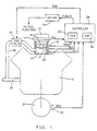
- air is provided to an internal combustion engine 10 through inlet air path commencing at inlet 12.
- the air passes from inlet 12 through mass airflow sensing means 14, such as a conventional mass airflow meter, which provides an output signal MAF indicative of the mass of air passing through the sensing means.
- throttle valve 16 such as may be a conventional butterfly valve which rotates within the inlet air path in accord with an operator commanded engine operating point.
- the rotational position of the valve is transduced via throttle position sensor 18, which may be a generally known rotational potentiometer which communicates an output signal TPOS indicative of the rotational position of the valve 16.
- a manifold pressure sensor 22 is disposed in the inlet air path such as in an engine intake manifold 20 between the throttle valve 16 and the engine 10, to transduce manifold absolute air pressure and communicate output signal MAP indicative thereof.
- a manifold air temperature sensor 21 is provided in the inlet air path such as in the engine intake manifold 20 to sense air temperature therein and communicate a signal MAT indicative thereof.
- EGR valve 40 such as a commercially available electrically-controlled solenoid valve provides for metering of the recirculated exhaust gas through conduit 38 in response to an electrical command EGR from controller 28.
- the electrical command may be in the form of a pulse width modulated command wherein the solenoid valve remains open for the duration of each duty cycle of the command and otherwise is closed.
- Engine output shaft 24 such as an engine crankshaft, rotates through operation of the engine 10 at a rate proportional to engine speed.
- Appendages or teeth are spaced about a circumferential portion of the shaft 24 and rotate past tooth passage sensing means 26, such as a conventional variable reluctance sensor which communicates passage of the teeth in the form of output signal RPM.
- the teeth may be spaced about the circumference of the shaft 24 such that each passage of a tooth by the sensing means 26 corresponds to an engine cylinder event.
- the shaft 24 may include two teeth equally spaced about the shaft circumference, such as 180 degrees apart. Additional teeth may be included for synchronisation of the teeth, as is generally understood in the engine control art.
- Controller 28 such as a conventional 32 bit microcontroller, including conventional random access memory RAM 30 and conventional read only memory ROM 32, receives input signals including the described MAF, TPOS, MAP, MAT and RPM, and determines engine control commands in response thereto, to provide for control of engine operation, such as in a manner consistent with generally known engine control practices.
- the input information may be applied in an estimation of inlet air rate to the engine cylinders.
- the estimate may be applied to the predictor of the reference incorporated herein for prediction of the inlet air rate to the cylinders R steps ahead of the estimation time.
- the prediction approach described in the incorporated reference relies on an accurate estimate or measurement of the engine state to be predicted. Any inaccuracy in the estimation or measurement will inject inaccuracy into the resulting prediction. For example, an R-step ahead prediction of inlet air rate to the engine cylinders starts with some measurement or estimate of the cylinder inlet air rate. The prediction accuracy benefits from improved accuracy in the measurement or estimate. Alternatively, any inaccuracy in the measurement or estimate will lead to inaccurate engine air/fuel ratio control, which may increase engine emissions.
- any engine control approach responsive to a sensed, measured, estimated or predicted cylinder inlet air rate will benefit from increased accuracy. It is within the scope of the present invention to provide an accurate measurement of cylinder inlet air rate to be applied to any of such systems that may benefit from such described increased accuracy.
- the step 110 of the incorporated reference requires a measurement or calculation of certain engine input parameters.
- the step 110 may require measurement of inlet air rate to the engine cylinders.
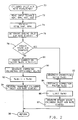
- the measurement or estimation of inlet air rate to the engine cylinders is provided through step-by-step execution of the operations of Figure 2, starting at a step 70.
- Figure 2 is iteratively executed, such as once per each engine cylinder event.
- values corresponding to the present iteration may have the index k, and values from the most recent prior iteration may have the index k-1, etc.
- the routine moves to a step 72, at which input signals are read by controller 28 ( Figure 1) and stored as corresponding values for this kth iteration including MAP(K), MAT(K), RPM(K), and MAF(K).
- the routine then moves to a step 74 to reference a nominal volumetric efficiency value VEo(K) as a function of stored input values MAP(K) and RPM(K).
- a nominal volumetric efficiency table VETBL may be generated through a vehicle calibration process in which volumetric efficiency is determined at each of a series of data points representing a corresponding series of paired RPM and MAP values. While the RPM and MAP vary with each data point in the table, other parameters are assumed to remain fixed through this calibration process. These other parameters include the fraction of EGR in the intake manifold, the temperature of air in the manifold MAT, and engine altitude. The assumption that such other parameters remain fixed through calibration greatly simplifies the calibration process, reduces the complexity of the process of referencing a VEo value, and yet, if applied with the corrections provided in accord with the present invention, does not reduce accuracy.
- VEo is referenced from the calibration table VETBL at the step 74 as the nominal volumetric efficiency value calibrated to correspond to RPM(K) and MAP(K), after which the engine inlet air rate EIAR(K) is determined at a step 76.
- EIAR(K) may be determined directly from measured mass airflow MAF input information, for example by integrating the MAF signal over a predetermined sample period such as the period between the kth and k-lth iterations of the present routine.
- the inventors intend that other known techniques for deriving an engine inlet air rate from engine parameter information may be used at the step 76 within the scope of this invention.
- the routine determines whether the engine inlet air dynamics may be characterised as steady state at a step 78.
- the manner of making such a steady state determination is provided as described in the copending U.S. patent application, serial no. 08/155263, filed November 22, 1993, assigned to the assignee of this application.
- that copending application describes analysis of a number of samples of engine intake manifold absolute pressure MAP, or throttle position TPOS to determine whether manifold filling or depletion is occurring presently. If any such filling or depletion is occurring, or any other condition reducing the accuracy of the mass airflow sensing means as an indicator of cylinder inlet air rate, steady state is not present.
- the present invention relies on the accuracy with which mass airflow information from mass airflow sensor 14 (Figure 1) may be used to predict individual cylinder inlet air rate under steady state conditions.
- steady state provided in the copending application no. 08/155,263, filed November 22, 1993, assigned to the assignee of this application, when steady state conditions are determined to be present, reliable cylinder inlet air rate information is available using mass airflow information. Accordingly, a comparison may be drawn between the reliable cylinder inlet air rate information and calibration information, such as from the nominal value VEo(K). Unmodelled effects from such slowly changing parameters as ambient temperature, ambient pressure (such as changes with vehicle altitude) and degree of dilution from recirculated engine exhaust gas EGR may be exposed through the comparison. Difficult calibration for these effects may thus be avoided and costly or marginally accurate sensors or inaccurate estimators of such parameters or their effects may likewise be avoided.
- a correction term may be generated from the comparison representing the effects of such parameters, and may be applied in subsequent cylinder inlet air rate estimation.
- the cylinder inlet air rate estimate may be used as a measurement input for use in the R-step ahead predictor of the incorporated reference.
- the correction term is updated only when reliable cylinder inlet air rate information is available for comparison with calibration values, but may be applied to correct for effects not modelled in such calibration values at all times, including times when reliable cylinder inlet air rate information may not be available.
- a series of cells may be defined each of which corresponds to a predetermined engine operating range and each of which has a dedicated correction term which is updated and applied only when the engine is operating in the corresponding operating range. Only one cell is active at any time, and the correction term for the active cell is updated according to a conventional update strategy, in response to the comparison between the nominal cylinder inlet air rate and the measured cylinder inlet air rate.
- the use of such cells and the manner in which the correction terms corresponding to each of such cells are updated, applied and stored is generally known in the engine control art, for example in the closed-loop engine air/fuel ratio control art to which the present invention pertains.
- the correction ratio ⁇ m(K) is the ratio of measured cylinder inlet air rate from the mass airflow meter 14 ( Figure 1) under steady state conditions to the estimated cylinder air rate based on a calibrated nominal volumetric efficiency VEo(K).
- ⁇ e(K) is limited at a step 86 to a predetermined reasonable correction range, such as between approximately 0.5 and 1.5 percent correction.
- the routine moves to a step 96 to return to prior operations, such as the measurement of other parameters in accord with the description of the step 110 of the incorporated reference.
- the routine moves to a step 80 to freeze or hold the correction factor ⁇ e() constant, by assigning it the value ⁇ (K-1) determined from the most recent execution of the routine of Figure 2.
- the output signal MAF from the mass airflow meter 14 ( Figure 1) is assumed to not be a reliable measure of cylinder inlet air rate due mainly to engine intake manifold filling or depletion. As such, there is no measure of cylinder inlet air rate with which to correct the calibrated nominal volumetric efficiency value VEo(K) described at the step 74.
- the ⁇ e() correction value adjusts for slowly changing parameters under non-steady state conditions, increasing speed density approach accuracy and overcoming many of the shortcomings commonly associated with speed density approaches.
- the corrected volumetric efficiency thus accounts for physical effects of unmodelled parameter value fluctuations on the rate at which air passes into the engine cylinders, so as to better characterise the cylinder inlet air rate. Any physical effects that would cause a variation in cylinder inlet air rate over a calibrated inlet air rate for engine speed and manifold pressure would be accounted for in the correction of this embodiment.
- This measured cylinder inlet air rate may be applied as the measurement of the cylinder inlet air state to be predicted in the R-step ahead approach of the incorporated reference, as described.
- the routine of Figure 2 returns to prior operations via the described step 96.
- a direct measure or estimate of quantity of recirculated engine exhaust gas EGR passing into the engine intake manifold may be available.
- a conventional pressure difference sensor (not shown) may be disposed across the EGR valve 40 ( Figure 1) in position to provide an output signal ⁇ Pegr indicative of the pressure drop across the valve 40 of known orifice size.
- the ⁇ Pegr signal may be monitored over a predetermined time period to determine ⁇ Pegr(K), the quantity of EGR passing through EGR conduit 38 ( Figure 1) into intake manifold 20 during that time period.
- the mass fraction of EGR in the intake manifold EGRf(K) may then be determined from ⁇ Pegr(K), MAP(K) and MAT(K), and may be applied directly in a measurement of the cylinder inlet air rate, rather than relying on a correction value, such as that determined in the preferred embodiment, to correct for the influence of EGR on cylinder inlet air rate.
- any inaccuracy in the determination of the mass fraction of EGR in the manifold may be compensated through the correction value, for example, due to error injected into the determination at the measurement or calculation stages.
- the correction value provided in accord with this invention provides compensation for any deviation in a parameter away from a modelled or measured value that tends to impact the accuracy of the cylinder inlet air rate measurement may be compensated within the scope of this invention.
- step 110 of the incorporated reference requires measurement of cylinder inlet air rate
- the routine of Figure 3 may be executed, starting at a step 140, and moving to read input signals including those described in the preferred embodiment hereof and the described pressure difference signal ⁇ Pegr(K) at a step 142.
- the routine estimates the mass EGR fraction EGRf(K) in the engine intake manifold 20 ( Figure 1) as a generally-known predetermined function of ⁇ Pegr(K), MAT(K), and MAP(K), at a step 144.
- a nominal volumetric efficiency value VEo(K) is referenced from a calibrated volumetric efficiency table VETBL through reference parameters such as MAP(K) and RPM(K), at a step 148.
- the determination of the volumetric efficiency entries in VETBL may be carried out as described in the preferred embodiment hereof.
- step 150 is executed to determine an engine inlet air rate EIAR(K), such as in the manner described in the preferred embodiment hereof at the step 76 of Figure 2.
- the routine then moves to the step 152 to determine if the engine inlet air dynamics are in steady state.
- the mass of air in the intake manifold Ma(K) is used in this embodiment to generate ⁇ m(K) so as to correct for the mass of EGR in the manifold directly.
- the correction of this embodiment is an air correction, not necessarily including information on the extent that EGR impacts the nominal volumetric efficiency VEo(K).
- the routine then estimates the correction factor ⁇ e(K) at a step 156, and limits it at a step 158, both of which steps may be carried out as described in the preferred embodiment hereof.
- the correction factor ⁇ e(K) is next applied at a step 162 to generate a corrected volumetric efficiency VEc(K).
- the mass airflow sensor is used in the generation and updating of the correction factor ⁇ e(K), but is not used in the measurement of the cylinder inlet air rate CIAR(K) under steady state conditions, indicating the usefulness of the correction factor determined in accord with this invention.
- a desire for a simplified control strategy or the use of an inexpensive mass airflow sensor may make such use of mass airflow information desirable.
- the correction factor ⁇ e(K) is then stored as ⁇ e(K-1) at a step 164.
- cylinder inlet air rate CIAR(K) is measured at a step 166 using the corrected volumetric efficiency value, such as in the manner described at the step 94 of Figure 2. The routine then returns to prior operations via the step 168.
- the calibration of the nominal volumetric efficiency table VETBL may be varied or made more complex by varying or adding parameters to the generation of the table, such as EGR quantity, altitude, or manifold air temperature.
- the correction provided in accord with this invention should not be limited to operation with a specific calibration, or to correction for a specific set or class of effects, as the highly reliable mass airflow information under steady state conditions may be used in combination with a wide variety of parameters to correct for virtually any unmodelled effect that operates to degrade calibrated volumetric efficiency accuracy.
Landscapes
- Engineering & Computer Science (AREA)
- Chemical & Material Sciences (AREA)
- Combustion & Propulsion (AREA)
- Mechanical Engineering (AREA)
- General Engineering & Computer Science (AREA)
- Combined Controls Of Internal Combustion Engines (AREA)
- Output Control And Ontrol Of Special Type Engine (AREA)
Claims (5)
- Verfahren zum Korrigieren einer Abschätzung einer Zylinderansaugluftrate (CIAR(K)) für einen Verbrennungsmotor, mit den Schritten, dass: eine Motoransaugluftrate (EIAR(K)) erfasst wird (70); eine Zylinderansaugluftrate (CIAR(K)) abgeschätzt wird (76); ein Wert erzeugt wird (82-87), der eine Abweichung der abgeschätzten Zylinderansaugluftrate (CIAR(K)) von der erfassten Motoransaugluftrate (EIAR(K)) weg darstellt; und ein Korrekturfaktor (γc(K)) zum Korrigieren der Abschätzung der Zylinderansaugluftrate (CIAR(K)) des Verbrennungsmotors als eine vorbestimmte Funktion des erzeugten Abweichungswertes (γm(K)) erzeugt wird; wobei ein stationärer Zustand des Motors diagnostiziert wird (28, 72, 74); und die Zylinderansaugluftrate (CIAR(K)) abgeschätzt und der Abweichungswert (γm(K)) erzeugt wird, wenn ein stationärer Zustand des Motors diagnostiziert worden ist;
dadurch gekennzeichnet, dass
die korrigierte Ansaugluftrate (CIAR(K)) erzeugt wird, indem ein korrigierter Wert eines volumetrischen Wirkungsgrades (VEc(K)) als eine Funktion eines vorbestimmten Satzes von Motorparametern (MAP(K), MAT(K)) und der Korrekturfaktor (γc(K)) verwendet werden. - Verfahren nach Anspruch 1, wobei der Schritt des Diagnostizierens eines stationären Zustandes des Motors ferner die Schritte umfasst, dass ein Wert eines vorbestimmten Motorparameters (MAP, TPOS), der das Füllen und Entleeren eines Motoransaugrohres angibt, erfasst wird; der erfasste Werte (MAP, TPOS) mit einem vorbestimmten Schwellenwert verglichen wird; und der stationäre Zustand des Motors diagnostiziert wird, wenn der erfasste Wert (MAP, TPOS) den vorbestimmten Schwellenwert nicht übersteigt.
- Verfahren nach Anspruch 2, wobei der vorbestimmte Parameter dem Motoransaugrohr-Luftdruck (MAP) entspricht.
- Verfahren nach Anspruch 2 oder Anspruch 3, wobei der erfasste Wert einer Änderungsrate entspricht.
- Verfahren nach Anspruch 1, wobei die vorbestimmten Motorparameter den Motoransaugrohr-Druck (MAP) und die Motoransaug-Lufttemperatur (MAT) umfassen.
Applications Claiming Priority (2)
| Application Number | Priority Date | Filing Date | Title |
|---|---|---|---|
| US217824 | 1994-03-25 | ||
| US08/217,824 US5465617A (en) | 1994-03-25 | 1994-03-25 | Internal combustion engine control |
Publications (3)
| Publication Number | Publication Date |
|---|---|
| EP0674101A2 EP0674101A2 (de) | 1995-09-27 |
| EP0674101A3 EP0674101A3 (de) | 1998-09-30 |
| EP0674101B1 true EP0674101B1 (de) | 2002-01-16 |
Family
ID=22812679
Family Applications (1)
| Application Number | Title | Priority Date | Filing Date |
|---|---|---|---|
| EP95200455A Expired - Lifetime EP0674101B1 (de) | 1994-03-25 | 1995-02-23 | Steuerung für Brennkraftmaschine |
Country Status (3)
| Country | Link |
|---|---|
| US (1) | US5465617A (de) |
| EP (1) | EP0674101B1 (de) |
| DE (1) | DE69524983T2 (de) |
Families Citing this family (61)
| Publication number | Priority date | Publication date | Assignee | Title |
|---|---|---|---|---|
| JPH08210173A (ja) * | 1995-02-02 | 1996-08-20 | Unisia Jecs Corp | スロットル弁の汚れ学習制御装置 |
| JP3011070B2 (ja) * | 1995-09-07 | 2000-02-21 | トヨタ自動車株式会社 | バルブタイミング連続可変機構付き内燃機関における吸入空気量検出装置 |
| US5577474A (en) * | 1995-11-29 | 1996-11-26 | General Motors Corporation | Torque estimation for engine speed control |
| JP3052813B2 (ja) * | 1995-12-05 | 2000-06-19 | トヨタ自動車株式会社 | 吸気量検出器の異常検出装置及び異常検出方法 |
| JPH09159578A (ja) * | 1995-12-08 | 1997-06-20 | Unisia Jecs Corp | 吸入空気量検出装置の性能診断装置 |
| US5753805A (en) * | 1996-12-02 | 1998-05-19 | General Motors Corporation | Method for determining pneumatic states in an internal combustion engine system |
| US5714683A (en) * | 1996-12-02 | 1998-02-03 | General Motors Corporation | Internal combustion engine intake port flow determination |
| US6279390B1 (en) * | 1996-12-17 | 2001-08-28 | Denso Corporation | Thermostat malfunction detecting system for engine cooling system |
| US5845627A (en) * | 1997-05-30 | 1998-12-08 | General Motors Corporation | Internal combustion engine pneumatic state estimator |
| US5941927A (en) * | 1997-09-17 | 1999-08-24 | Robert Bosch Gmbh | Method and apparatus for determining the gas temperature in an internal combustion engine |
| US6308694B1 (en) | 1999-01-11 | 2001-10-30 | Ford Global Technologies, Inc. | Flow measurement and control |
| US6293267B1 (en) * | 2000-03-23 | 2001-09-25 | Delphi Technologies, Inc. | Flow-based control method for an engine control valve |
| FR2834532B1 (fr) * | 2002-01-09 | 2004-04-02 | Peugeot Citroen Automobiles Sa | Systeme de determination de la masse de gaz admise dans un moteur a combustion interne de vehicule automobile |
| US6655353B1 (en) * | 2002-05-17 | 2003-12-02 | General Motors Corporation | Cylinder deactivation engine control system with torque matching |
| US6769403B2 (en) * | 2002-05-17 | 2004-08-03 | General Motors Corporation | Spark retard control during cylinder transitions in a displacement on demand engine |
| US6760656B2 (en) * | 2002-05-17 | 2004-07-06 | General Motors Corporation | Airflow estimation for engines with displacement on demand |
| EP1429012A1 (de) * | 2002-12-09 | 2004-06-16 | Ford Global Technologies, Inc. | Verfahren und System zur Schätzung der Zylinderluftmenge einer Brennkraftmaschine |
| US6802302B1 (en) * | 2003-04-08 | 2004-10-12 | Cummins, Inc. | System for diagnosing EGR flow rate operation |
| JP4291624B2 (ja) * | 2003-05-27 | 2009-07-08 | トヨタ自動車株式会社 | 内燃機関の制御 |
| US7010413B2 (en) * | 2003-09-17 | 2006-03-07 | General Motors Corporation | Cylinder mass air flow prediction model |
| US6959684B2 (en) * | 2003-10-14 | 2005-11-01 | General Motors Corporation | Torque based cylinder deactivation with vacuum correction |
| US7000589B2 (en) * | 2004-06-15 | 2006-02-21 | General Motors Corporation | Determining manifold pressure based on engine torque control |
| US7793641B2 (en) * | 2005-04-29 | 2010-09-14 | Gm Global Technology Operations, Inc. | Model-based fuel control for engine start and crank-to-run transition |
| US7302937B2 (en) * | 2005-04-29 | 2007-12-04 | Gm Global Technology Operations, Inc. | Calibration of model-based fuel control for engine start and crank to run transition |
| US7512479B1 (en) * | 2007-11-19 | 2009-03-31 | Southwest Research Institute | Air fraction estimation for internal combustion engines with dual-loop EGR systems |
| JP2009275679A (ja) * | 2008-05-19 | 2009-11-26 | Toyota Motor Corp | 内燃機関の吸気制御装置および内燃機関の自動適合装置 |
| US9157390B2 (en) | 2011-09-21 | 2015-10-13 | GM Global Technology Operations LLC | Selective exhaust gas recirculation diagnostic systems and methods |
| US20130226435A1 (en) * | 2012-02-29 | 2013-08-29 | GM Global Technology Operations LLC | Systems and methods for adjusting an estimated flow rate of exhaust gas passing through an exhaust gas recirculation valve |
| US10066564B2 (en) | 2012-06-07 | 2018-09-04 | GM Global Technology Operations LLC | Humidity determination and compensation systems and methods using an intake oxygen sensor |
| US9249764B2 (en) | 2012-03-06 | 2016-02-02 | GM Global Technology Operations LLC | Engine control systems and methods with humidity sensors |
| US9932917B2 (en) | 2012-03-21 | 2018-04-03 | GM Global Technology Operations LLC | Exhaust gas recirculation control systems and methods |
| US9719439B2 (en) | 2012-08-24 | 2017-08-01 | GM Global Technology Operations LLC | System and method for controlling spark timing when cylinders of an engine are deactivated to reduce noise and vibration |
| US9458778B2 (en) | 2012-08-24 | 2016-10-04 | GM Global Technology Operations LLC | Cylinder activation and deactivation control systems and methods |
| US9376973B2 (en) | 2012-09-10 | 2016-06-28 | GM Global Technology Operations LLC | Volumetric efficiency determination systems and methods |
| US9534550B2 (en) * | 2012-09-10 | 2017-01-03 | GM Global Technology Operations LLC | Air per cylinder determination systems and methods |
| US9140622B2 (en) | 2012-09-10 | 2015-09-22 | GM Global Technology Operations LLC | System and method for controlling a firing sequence of an engine to reduce vibration when cylinders of the engine are deactivated |
| US9239024B2 (en) | 2012-09-10 | 2016-01-19 | GM Global Technology Operations LLC | Recursive firing pattern algorithm for variable cylinder deactivation in transient operation |
| US9458779B2 (en) | 2013-01-07 | 2016-10-04 | GM Global Technology Operations LLC | Intake runner temperature determination systems and methods |
| US9458780B2 (en) | 2012-09-10 | 2016-10-04 | GM Global Technology Operations LLC | Systems and methods for controlling cylinder deactivation periods and patterns |
| US9249748B2 (en) | 2012-10-03 | 2016-02-02 | GM Global Technology Operations LLC | System and method for controlling a firing sequence of an engine to reduce vibration when cylinders of the engine are deactivated |
| US9249747B2 (en) | 2012-09-10 | 2016-02-02 | GM Global Technology Operations LLC | Air mass determination for cylinder activation and deactivation control systems |
| US9382853B2 (en) | 2013-01-22 | 2016-07-05 | GM Global Technology Operations LLC | Cylinder control systems and methods for discouraging resonant frequency operation |
| US9726139B2 (en) | 2012-09-10 | 2017-08-08 | GM Global Technology Operations LLC | System and method for controlling a firing sequence of an engine to reduce vibration when cylinders of the engine are deactivated |
| US9638121B2 (en) * | 2012-08-24 | 2017-05-02 | GM Global Technology Operations LLC | System and method for deactivating a cylinder of an engine and reactivating the cylinder based on an estimated trapped air mass |
| US9416743B2 (en) * | 2012-10-03 | 2016-08-16 | GM Global Technology Operations LLC | Cylinder activation/deactivation sequence control systems and methods |
| US9650978B2 (en) * | 2013-01-07 | 2017-05-16 | GM Global Technology Operations LLC | System and method for randomly adjusting a firing frequency of an engine to reduce vibration when cylinders of the engine are deactivated |
| US8979708B2 (en) | 2013-01-07 | 2015-03-17 | GM Global Technology Operations LLC | Torque converter clutch slip control systems and methods based on active cylinder count |
| US10227939B2 (en) | 2012-08-24 | 2019-03-12 | GM Global Technology Operations LLC | Cylinder deactivation pattern matching |
| US9249749B2 (en) | 2012-10-15 | 2016-02-02 | GM Global Technology Operations LLC | System and method for controlling a firing pattern of an engine to reduce vibration when cylinders of the engine are deactivated |
| US9222427B2 (en) | 2012-09-10 | 2015-12-29 | GM Global Technology Operations LLC | Intake port pressure prediction for cylinder activation and deactivation control systems |
| US9341133B2 (en) | 2013-03-06 | 2016-05-17 | GM Global Technology Operations LLC | Exhaust gas recirculation control systems and methods |
| US9494092B2 (en) | 2013-03-13 | 2016-11-15 | GM Global Technology Operations LLC | System and method for predicting parameters associated with airflow through an engine |
| US9631567B2 (en) | 2013-08-15 | 2017-04-25 | GM Global Technology Operations LLC | Sensor based measurement and purge control of fuel vapors in internal combustion engines |
| US9441550B2 (en) | 2014-06-10 | 2016-09-13 | GM Global Technology Operations LLC | Cylinder firing fraction determination and control systems and methods |
| US9341128B2 (en) | 2014-06-12 | 2016-05-17 | GM Global Technology Operations LLC | Fuel consumption based cylinder activation and deactivation control systems and methods |
| US9556811B2 (en) | 2014-06-20 | 2017-01-31 | GM Global Technology Operations LLC | Firing pattern management for improved transient vibration in variable cylinder deactivation mode |
| US9599047B2 (en) | 2014-11-20 | 2017-03-21 | GM Global Technology Operations LLC | Combination cylinder state and transmission gear control systems and methods |
| US10337441B2 (en) | 2015-06-09 | 2019-07-02 | GM Global Technology Operations LLC | Air per cylinder determination systems and methods |
| JP7188360B2 (ja) * | 2019-11-07 | 2022-12-13 | トヨタ自動車株式会社 | エンジン制御装置 |
| FR3118100B1 (fr) * | 2020-12-17 | 2023-10-06 | Renault Sas | Système et procédé de commande d’un moteur à combustion interne basée sur le rendement de remplissage |
| FR3144844B1 (fr) * | 2023-01-11 | 2024-11-22 | Psa Automobiles Sa | Procédé de détermination d'un remplissage maximal atteignable pour un moteur à combustion interne suralimenté |
Family Cites Families (13)
| Publication number | Priority date | Publication date | Assignee | Title |
|---|---|---|---|---|
| JPS60178952A (ja) * | 1984-02-27 | 1985-09-12 | Mitsubishi Electric Corp | 内燃機関の燃料噴射制御装置 |
| JPS6278449A (ja) * | 1985-10-02 | 1987-04-10 | Mitsubishi Electric Corp | 内燃機関の燃料噴射制御装置 |
| JPS62261645A (ja) * | 1986-05-06 | 1987-11-13 | Fuji Heavy Ind Ltd | エンジン制御装置 |
| JP2577211B2 (ja) * | 1986-08-27 | 1997-01-29 | 株式会社ユニシアジェックス | 内燃機関の基本燃料噴射量設定装置 |
| KR930000347B1 (ko) * | 1988-04-28 | 1993-01-16 | 가부시기가이샤 히다찌세이사꾸쇼 | 내연기관용 공연비제어장치 |
| US5003950A (en) * | 1988-06-15 | 1991-04-02 | Toyota Jidosha Kabushiki Kaisha | Apparatus for control and intake air amount prediction in an internal combustion engine |
| US5211056A (en) * | 1989-04-14 | 1993-05-18 | Hitachi, Ltd. | Thermal type intake air flow measuring instrument |
| JPH0760107B2 (ja) * | 1989-07-11 | 1995-06-28 | 三菱電機株式会社 | 熱式流量センサの信号処理方法 |
| US5273019A (en) * | 1990-11-26 | 1993-12-28 | General Motors Corporation | Apparatus with dynamic prediction of EGR in the intake manifold |
| US5270935A (en) * | 1990-11-26 | 1993-12-14 | General Motors Corporation | Engine with prediction/estimation air flow determination |
| US5070846A (en) * | 1990-11-26 | 1991-12-10 | General Motors Corporation | Method for estimating and correcting bias errors in a software air meter |
| US5228336A (en) * | 1991-01-18 | 1993-07-20 | Nissan Motor Co., Ltd. | Engine intake air volume detection apparatus |
| JP2812048B2 (ja) * | 1992-03-27 | 1998-10-15 | 三菱電機株式会社 | 内燃機関の電子制御装置 |
-
1994
- 1994-03-25 US US08/217,824 patent/US5465617A/en not_active Expired - Lifetime
-
1995
- 1995-02-23 DE DE69524983T patent/DE69524983T2/de not_active Expired - Lifetime
- 1995-02-23 EP EP95200455A patent/EP0674101B1/de not_active Expired - Lifetime
Also Published As
| Publication number | Publication date |
|---|---|
| EP0674101A2 (de) | 1995-09-27 |
| US5465617A (en) | 1995-11-14 |
| DE69524983T2 (de) | 2002-08-22 |
| EP0674101A3 (de) | 1998-09-30 |
| DE69524983D1 (de) | 2002-02-21 |
Similar Documents
| Publication | Publication Date | Title |
|---|---|---|
| EP0674101B1 (de) | Steuerung für Brennkraftmaschine | |
| US6636796B2 (en) | Method and system for engine air-charge estimation | |
| US6687600B2 (en) | System and method for air flow and EGR flow estimation | |
| US5654501A (en) | Engine controller with air meter compensation | |
| US5596972A (en) | Integrated fueling control | |
| EP0582085A2 (de) | Brennstoffdosierungsteuersystem und Verfahren zum Schätzen des Zylinderluftstroms in Verbrennungsmotoren | |
| US4789939A (en) | Adaptive air fuel control using hydrocarbon variability feedback | |
| EP0659994B1 (de) | Steuerungssystem mit geschlossenem Regelkreis einer Dieselbrennkraftmaschine | |
| US5522365A (en) | Internal combustion engine control | |
| US5651353A (en) | Internal combustion engine control | |
| US5421302A (en) | Engine speed control state prediction | |
| US6282485B1 (en) | Air estimation system and method | |
| US4911133A (en) | Fuel injection control system of automotive engine | |
| WO2006019549A2 (en) | Estimation of oxygen concentration in the intake manifold of an unthrottled lean burn engine | |
| US5520153A (en) | Internal combustion engine control | |
| US5474052A (en) | Automated method for cold transient fuel compensation calibration | |
| US5666931A (en) | Integrated engine dilution control | |
| JP3138467B2 (ja) | 燃料量を定める方法 | |
| EP0534506B1 (de) | System zur Steuerung des Luft/Kraftstoff-Verhältnisses für Brennkraftmotoren mit Steuerung der asynchronen Kraftstoffzuführung | |
| JPH0819880B2 (ja) | 排気ガス再循環制御装置 | |
| JP2754744B2 (ja) | 内燃機関の燃料噴射量制御装置 | |
| JP2712821B2 (ja) | 内燃機関の燃料噴射量制御装置 | |
| US5803046A (en) | Ignition timing control | |
| JP2524703B2 (ja) | エンジン制御装置 | |
| JP2830461B2 (ja) | 内燃機関の燃料噴射量制御装置 |
Legal Events
| Date | Code | Title | Description |
|---|---|---|---|
| PUAI | Public reference made under article 153(3) epc to a published international application that has entered the european phase |
Free format text: ORIGINAL CODE: 0009012 |
|
| AK | Designated contracting states |
Kind code of ref document: A2 Designated state(s): DE FR GB |
|
| PUAL | Search report despatched |
Free format text: ORIGINAL CODE: 0009013 |
|
| AK | Designated contracting states |
Kind code of ref document: A3 Designated state(s): DE FR GB |
|
| 17P | Request for examination filed |
Effective date: 19990322 |
|
| 17Q | First examination report despatched |
Effective date: 20000531 |
|
| GRAG | Despatch of communication of intention to grant |
Free format text: ORIGINAL CODE: EPIDOS AGRA |
|
| GRAG | Despatch of communication of intention to grant |
Free format text: ORIGINAL CODE: EPIDOS AGRA |
|
| GRAG | Despatch of communication of intention to grant |
Free format text: ORIGINAL CODE: EPIDOS AGRA |
|
| GRAH | Despatch of communication of intention to grant a patent |
Free format text: ORIGINAL CODE: EPIDOS IGRA |
|
| GRAH | Despatch of communication of intention to grant a patent |
Free format text: ORIGINAL CODE: EPIDOS IGRA |
|
| GRAA | (expected) grant |
Free format text: ORIGINAL CODE: 0009210 |
|
| REG | Reference to a national code |
Ref country code: GB Ref legal event code: IF02 |
|
| AK | Designated contracting states |
Kind code of ref document: B1 Designated state(s): DE FR GB |
|
| REF | Corresponds to: |
Ref document number: 69524983 Country of ref document: DE Date of ref document: 20020221 |
|
| PGFP | Annual fee paid to national office [announced via postgrant information from national office to epo] |
Ref country code: GB Payment date: 20020313 Year of fee payment: 8 |
|
| PGFP | Annual fee paid to national office [announced via postgrant information from national office to epo] |
Ref country code: FR Payment date: 20020319 Year of fee payment: 8 |
|
| ET | Fr: translation filed | ||
| PLBE | No opposition filed within time limit |
Free format text: ORIGINAL CODE: 0009261 |
|
| STAA | Information on the status of an ep patent application or granted ep patent |
Free format text: STATUS: NO OPPOSITION FILED WITHIN TIME LIMIT |
|
| 26N | No opposition filed | ||
| PG25 | Lapsed in a contracting state [announced via postgrant information from national office to epo] |
Ref country code: GB Free format text: LAPSE BECAUSE OF NON-PAYMENT OF DUE FEES Effective date: 20030223 |
|
| GBPC | Gb: european patent ceased through non-payment of renewal fee | ||
| PG25 | Lapsed in a contracting state [announced via postgrant information from national office to epo] |
Ref country code: FR Free format text: LAPSE BECAUSE OF NON-PAYMENT OF DUE FEES Effective date: 20031031 |
|
| REG | Reference to a national code |
Ref country code: FR Ref legal event code: ST |
|
| PGFP | Annual fee paid to national office [announced via postgrant information from national office to epo] |
Ref country code: DE Payment date: 20140417 Year of fee payment: 20 |
|
| REG | Reference to a national code |
Ref country code: DE Ref legal event code: R071 Ref document number: 69524983 Country of ref document: DE |
|
| REG | Reference to a national code |
Ref country code: DE Ref legal event code: R071 Ref document number: 69524983 Country of ref document: DE |