EP0674928A1 - Méthode et appareil de dégazage de fluides à haute viscosité - Google Patents
Méthode et appareil de dégazage de fluides à haute viscosité Download PDFInfo
- Publication number
- EP0674928A1 EP0674928A1 EP95103707A EP95103707A EP0674928A1 EP 0674928 A1 EP0674928 A1 EP 0674928A1 EP 95103707 A EP95103707 A EP 95103707A EP 95103707 A EP95103707 A EP 95103707A EP 0674928 A1 EP0674928 A1 EP 0674928A1
- Authority
- EP
- European Patent Office
- Prior art keywords
- fluid
- chamber
- nozzle
- slide member
- slide
- Prior art date
- Legal status (The legal status is an assumption and is not a legal conclusion. Google has not performed a legal analysis and makes no representation as to the accuracy of the status listed.)
- Granted
Links
- 239000012530 fluid Substances 0.000 title claims abstract description 139
- 238000007872 degassing Methods 0.000 title claims abstract description 27
- 238000000034 method Methods 0.000 title claims abstract description 15
- 239000000463 material Substances 0.000 claims abstract description 48
- 230000000694 effects Effects 0.000 claims abstract description 13
- 230000001747 exhibiting effect Effects 0.000 claims description 4
- 230000003247 decreasing effect Effects 0.000 claims description 3
- 230000001965 increasing effect Effects 0.000 claims description 3
- 230000001419 dependent effect Effects 0.000 claims 1
- 238000012544 monitoring process Methods 0.000 claims 1
- 230000007480 spreading Effects 0.000 abstract description 3
- 238000007599 discharging Methods 0.000 abstract 1
- 239000000853 adhesive Substances 0.000 description 5
- 230000001070 adhesive effect Effects 0.000 description 5
- 239000000565 sealant Substances 0.000 description 5
- 230000009471 action Effects 0.000 description 4
- 230000002411 adverse Effects 0.000 description 2
- 230000003466 anti-cipated effect Effects 0.000 description 2
- 239000011324 bead Substances 0.000 description 2
- 230000008859 change Effects 0.000 description 2
- 238000007796 conventional method Methods 0.000 description 2
- 239000006185 dispersion Substances 0.000 description 2
- 239000000356 contaminant Substances 0.000 description 1
- 230000002708 enhancing effect Effects 0.000 description 1
- 230000001788 irregular Effects 0.000 description 1
- 238000012986 modification Methods 0.000 description 1
- 230000004048 modification Effects 0.000 description 1
- 210000002445 nipple Anatomy 0.000 description 1
- 238000005086 pumping Methods 0.000 description 1
- 230000009467 reduction Effects 0.000 description 1
- 238000009849 vacuum degassing Methods 0.000 description 1
- 230000000007 visual effect Effects 0.000 description 1
- XLYOFNOQVPJJNP-UHFFFAOYSA-N water Substances O XLYOFNOQVPJJNP-UHFFFAOYSA-N 0.000 description 1
Images


Classifications
-
- B—PERFORMING OPERATIONS; TRANSPORTING
- B01—PHYSICAL OR CHEMICAL PROCESSES OR APPARATUS IN GENERAL
- B01D—SEPARATION
- B01D19/00—Degasification of liquids
- B01D19/0042—Degasification of liquids modifying the liquid flow
- B01D19/0047—Atomizing, spraying, trickling
-
- B—PERFORMING OPERATIONS; TRANSPORTING
- B01—PHYSICAL OR CHEMICAL PROCESSES OR APPARATUS IN GENERAL
- B01D—SEPARATION
- B01D19/00—Degasification of liquids
- B01D19/0021—Degasification of liquids by bringing the liquid in a thin layer
-
- B—PERFORMING OPERATIONS; TRANSPORTING
- B01—PHYSICAL OR CHEMICAL PROCESSES OR APPARATUS IN GENERAL
- B01D—SEPARATION
- B01D19/00—Degasification of liquids
- B01D19/0063—Regulation, control including valves and floats
Definitions
- This invention generally pertains to dispensing systems which use high viscosity materials in their operation such as, for example, high viscosity adhesives, sealants, and/or caulks.
- this invention pertains to a method and apparatus for degassing high viscosity fluid materials such that these may be dispensed in a continuous and uninterrupted manner to a workpiece.
- this invention provides a method and a vacuum chamber configuration for degassing high viscosity fluid materials such that, when the material is dispensed from a nozzle onto a workpiece, it is devoid of air bubbles which adversely affect the quality of a product requiring the material as an integral part of its structure.
- a product may require the application of a sealant or caulk to seal out contaminants which may enter the product and a continuous bead of such sealant or caulk is required to maintain seal integrity.
- any air bubbles within the dispensed material may cause an interruption in the material bead as it is being dispensed from a nozzle. Such interruptions are not acceptable. There is therefore, a need for a method or means to effectively degas high viscosity fluid materials of the type listed above such that these type materials may be dispensed automatically without interruption and in a continuous manner.
- a method for degassing a high viscosity fluid comprising the steps of: providing a chamber for collecting a volume of a high viscosity fluid material; mounting a slide member within the chamber at an angular position with respect to a fluid inlet into the chamber; spreading fluid onto the slide member as it enters the chamber; and, allowing the fluid to move down the slide member in laminar flow while subjecting the chamber to a vacuum.
- an apparatus for degassing a high viscosity fluid material comprising in combination: a vertically oriented chamber having a fluid inlet at the top end and a collecting reservoir and exit port at the bottom end; means for drawing and controlling a vacuum within the the chamber; a slotted wide-mouthed nozzle mounted within the chamber towards its top end to receive fluid entering the chamber; a longitudinal channel-shaped slide member mounted within the chamber having a top end positioned relative to the nozzle and disposed angularly downwardly towards the chamber reservoir; the nozzle supplying fluid to the top end of the channel slide member such that the fluid exhibits laminar flow as it moves down the slide and a vacuum drawn on the chamber effects a release of any gaseous-materials contained within the fluid as it moves downwardly and into the chamber reservoir.
- the dispensing of the fluid from the nozzle in a wide pattern also provides a large surface area for exposer to the vacuum of the chamber to help in drawing off entrapped gas.
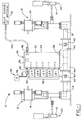
- a material dispensing system is illustrated and generally indicated by reference numeral 10.
- the system 10 comprises at least one dispensing apparatus 12 (two are shown) which includes a pump 14 and a dispensing nozzle 16, the apparatus 12 being adapted for drawing a fluid material into an entry port 18 and pumping it out of an exit port 20 at the nozzle 16.
- dispensing apparatus 12 Various configurations of dispensing apparatus 12 are known and used in the arts and these may be adapted for operation in an automated system which distributes a high viscosity fluid such as an adhesive or sealant to a workpiece (not shown).
- the apparatus 12 may draw the high viscosity fluid directly from a souce 22 of such type fluid material but this has been found to create problems with air bubbles in the fluid, problems which are not acceptable in many of these type operations.
- a degassing apparatus is interposed between the source of high viscosity materials 22 and the dispensing apparatus 12 and it is generally indicated in the drawing at reference numeral 30.
- the degassing apparatus 30 generally comprises a chamber 32 having vertically oriented walls 34 enclosed at a top end by a cap closure 36 and at a bottom end by a material receiving reservoir 38.
- the reservoir 38 may include a water jacket 44 which is fitted about the base of the chamber to maintain a proper temperature within the reservoir 38.
- the reservoir has an exit fitting 40 which is fitted to a control valve 42 and this in turn is connected to the dispensing apparatus 12 at the inlet port 18 using any of the conventional methods or techniques for effecting such connection.
- the degassing apparatus 30 has an inlet fitting or port 46 which is connected to a bulk source of high viscosity fluid material 22 via tubing or like means 48, the fluid being moved or pumped under an appropriate pressure to the apparatus 30.
- the apparatus 30 also includes a vacuum control generally indicated at reference numeral 50 and it comprises a vacuum port 52, a switch controller 54, and a vacuum pump 56 and these effect and maintain a desired and/or predetermined vacuum within the chamber 32.
- the apparatus 30 also includes fluid level control means generally indicated at numeral 60 and these comprise a number of fluid level detectors 62.
- the level detectors 62 are designated LD1-LD5 and these are connected into the chamber 32 at various levels and their specific operation will be described in more detail hereinafter.
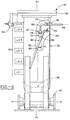
- a degassing chamber 32 includes a fluid receiving assembly generally indicated at reference numeral 70.
- the assembly 70 comprises a wide-mouthed or slotted nozzle 72 that is adapted for connection to the fluid inlet 46 via fittings 74 and an interconnecting pipe or tube 76.
- the tube 76 is bent downwardly from the inlet 46 at an angle of 90° with reference to a longitudinal Ay chamber axis.
- the nozzle 72 accepts a fluid material and feeds it onto a slide member 80 which is mounted or otherwise affixed to the interior of the chamber wall 34.
- the slide member 80 is a substantially shallow U-shaped member defined by a bottom wall or slide surface 82 and side walls 84 which extend the length of the bottom 82.
- the slide member 80 is mounted in a manner and relationship to the slotted nozzle 72 such that a fluid material is spread out onto the slide surface 82 at the top end of the slide member 80.
- the slide member 80 is angularaly disposed within the chamber 32 at an angle ⁇ with reference to the chamber Ay axis such that fluid materials fed onto the slide surface 82 move downwardly towards the chamber reservoir 38.
- the slot nozzle 72 comprises a rectangularly shaped body 100 exhibiting a width "W" that is greater than any or its other dimensions.
- the body 100 is defined by a frontal wall 102 having a face surface 102a that is angularly disposed with respect to a rear wall 104, and this, at an angle ⁇ 1 with reference to the Ay axis.
- the body 100 is further defined by a top wall 106 that is parallel to a bottom wall 108 and these are interconnected by end walls 110.
- the nozzle 72 is characterized by a bore or input port 112 in the top wall 106 and it is intercepted by a substantially semicircular slot bore or exit port 114 which penetrates rearwardly from the frontal face surface 102a.
- the input port 112 may be a smooth bore or it may be threaded so as to adapt to a double-ended threaded nipple fitting 116 which connects to the fluid supply tube 76 via a connector 74 as shown in Fig. 3.
- the bottom wall 108 defines the limit extent of the slot bore 114 and it exhibits a shorter front-to-rear dimension by a specific amount such as to establish a gap dimension "g" as illustrated in Figs. 3 and 6 of the drawings.
- the gap dimension is thus defined by the difference dimension of the frontal face surface 108a of the bottom wall 108 and the frontal face surface 102a of the front wall 102. Further, the gap "g" extends across the full width of the slot bore or exit port 114 of the nozzle 72.
- the slide member 80 comprises a slide surface 82 and side walls 84 and these define a channel which carries a fluid material from the slot nozzle 72 to the chamber reservoir 38.
- the slide member 80 is mounted within the chamber 32 by way of a support member 88 having a top end formed to a flange 88a.
- the flange 88a is bent at an angle ⁇ + 90° with reference to the chamber Ay axis as illustrated in Fig. 3 and it is carried by mounting means generally indicated at reference numeral 90 in the drawing.
- the mounting means 90 may comprise a bolt or weld stud 92 affixed to a bracket 96 and locknuts 94.
- the bracket 96 will be welded or otherwise secured to the chamber wall 34 while the support member 88 is secured to the bracket via a plurality of bolts 92 as shown.
- the slide member 80 is mounted to the support member 88 by way of U-shaped hooks 86 that are affixed to the slide member 80 at its top end and these are hung onto the support member flange 88a via suitably configured apertures 88b in the flange. In this manner the slide member 80 may be easily removed for servicing and/or replaced.
- the angular position of the frontal face surface 102a of the wall 102 may be such that the angle ⁇ of the slide member 80 is equal to the angle ⁇ 1 of the face surface 102a.
- the slide member is hung onto a support member 88 that exhibits an angle ⁇ that is the same as the angle of the nozzle frontal face surface 102a.
- the frontal face surface 102a may be positioned to abut the slide surface 82.
- This mounting is not advantageous inasmuch as it may result in fluid materials being drawn upwardly between the frontal fade surface 102a and the slide surface 82.
- a doctor blade member 120 may be mounted to the frontal face surface 102a by using appropriate screws 130 threaded into bores 132 in the frontal wall 102 of the nozzle.
- the doctor blade 120 may be any of numerous cross-sectional shapes but, preferably it will be shaped to establish an exit gap "g" suitable for passing a particular viscosity fluid as well as to function to mate with the slide surface 82.
- a suitable doctor blade 120 may be defined by a frontal face 122 that is angularly disposed with respect to a rear face 124 to establish an end 126 that is greater in dimension than an opposite end 128.
- This cross-sectional configuration is that of a wedge wherein the rear face 124 may be abutted to the frontal face surface 102a of the nozzle front wall 102 while the front face 122 is abutted to the slide surface 82 of the slide member 80.
- the doctor blade 120 is preferably greater in dimension between the ends 126-128 than is the height dimension of the nozzle between the top 106 and the bottom 108 as clearly evident in Fig. 3 such that it will extend beyond the bottom wall 108 by a certain amount.
- the exit gap "g" may not be adaquate for passing all of the ranges of viscosities of fluid materials that one may wish to degas in the chamber 30.
- a lower range viscosity fluid may pass through a particular gap "g”
- a higher range viscosity fluid may be all but blocked from exiting the nozzle 72.
- the gap "g” may be varied to accomodate passage of various viscosity fluid materials and this may be accomplished as illustrated in Fig. 6 of the drawings.
- a bottom wall 108 of the nozzle body 100 may comprise a separate wall member which is secured to the body using any conventional fastening means.
- the wall member 108 may be adjustable along an interface line indicated in ghost dot-dashed lines at reference numeral 140 and it may be configured with slots so as to be movable in the direction of reference arrow 142. This will, of course, effect a change in the gap "g" dimension so as to accomodate various viscosity fluid materials. Other means may be used to accomplish varying of the gap "g" and the invention, therefore, is not considered limited to the particular manner described above and/or illustrated in the drawing.
- the slide surface angle ⁇ may be adjustable for the various fluid viscosities to be degassed in the chamber 32.
- the angle ⁇ may be within the range of 20°-25° for lower viscosity materials but these angles will be too steep so as to cause higher viscosity fluids to drop off of the slide surface 82.
- This action will result in defeating the purposes of the invention as free falling droplets tend to generate air bubbles in the fluid volume that is being collected in the chamber reservoir 38.
- the angle ⁇ of the slide surface 82 may be increased or decreased depending upon the viscosity of the fluid material being passed through the nozzle 72.
- the angle ⁇ may be changed by merely changing the support member 88 to another one having a mounting flange 88 exhibiting a greater or lesser angle ⁇ as required.
- the slide surface angle ⁇ must be established such that a fluid material will flow smoothly on the slide surface i.e., laminar flow is established.
- the angle ⁇ will preferably be within the range of 20°-30° with reference to a vertical Ay axis of the chamber. While fluid materials exhibiting a viscosity of at least 80,000 centipoise have been used in conjunction with this range of angles, it is believed that this range may also be suitable for materials having a viscosity less than 80,000 centipoise. Also, low levels of vacuum drawn on the chamber 32 in the range of 1/3 to 1/2 atmosphere may be used to remove large air pockets and/or bubbles within a fluid of a particular viscosity. Higher levels of vacuum, i.e., less than 10% atmosphere, may be applied to de-gassing fluids having dissolved air and such vacuum may also be applied to removing volatile components from some types of fluid materials.
- the degassing apparatus 30 also includes a number of level detectors LD1 through LD5. These provide an important function in a continuous degassing operation such that the system does not get shut down because of a lack of or an over abundance of fluid volume within the chamber.
- the level detector LD1 is an emergency shut off device which shuts down the system should the fluid level get too low. Because one does not want such shut down to happen as this will increase the possibility of air entering the system, a warning level detector LD2 is provided which gives a visual and/or sound warning to an operator of an impending low level condition within the chamber 32.
- a high level detector LD5 is provided which automatically shuts down the operation should the volume level exceed a safe upper level condition.
- Two additional level detectors LD3 and LD4 are also shown in the drawing and these are used to move the fluid volume level up and down between the two levels. For example, when the fluid volume level drops to LD3, a signal is provided which effects an increase in the volume being fed into the inlet 46. As the volume increases to level LD4, a signal is provided which effects a reduction in the volume being fed into the inlet 46. allowing the fluid volume level to begin dropping again.
- This action of raising and lowering of the reservoir volume level forces any air bubbles which may exist on the fluid surface in the reservoir against the chamber walls where they are burst. It is, of course, anticipated that one may effect a change in the reservoir level by either increasing or decreasing the amount being drawn out of the reservoir by the dispensing apparatus 12.
- the invention therefore, is not considered limited by the particular action taken to accomplish this.
- the gap "g" at the nozzle 72 may be adjusted as well as the angle ⁇ of of the slide surface 82 and because a differential pressure exists at the gap, air bubble dispersion may be optimized at this point in the sysem.
- the vacuum condition may be adjusted to increase bubble dispersion and the volume level in the reservoir may be moved up and down so as to burst any bubbles on the surface of the fluid in the reservoir.
Landscapes
- Chemical & Material Sciences (AREA)
- Chemical Kinetics & Catalysis (AREA)
- Degasification And Air Bubble Elimination (AREA)
- Coating Apparatus (AREA)
- Processing And Handling Of Plastics And Other Materials For Molding In General (AREA)
Applications Claiming Priority (2)
| Application Number | Priority Date | Filing Date | Title |
|---|---|---|---|
| US08/218,727 US5509954A (en) | 1994-03-28 | 1994-03-28 | Method and apparatus for degassing high viscosity fluids |
| US218727 | 1994-03-28 |
Publications (2)
| Publication Number | Publication Date |
|---|---|
| EP0674928A1 true EP0674928A1 (fr) | 1995-10-04 |
| EP0674928B1 EP0674928B1 (fr) | 1998-06-03 |
Family
ID=22816267
Family Applications (1)
| Application Number | Title | Priority Date | Filing Date |
|---|---|---|---|
| EP95103707A Expired - Lifetime EP0674928B1 (fr) | 1994-03-28 | 1995-03-15 | Appareil de dégazage de fluides à haute viscosité |
Country Status (6)
| Country | Link |
|---|---|
| US (1) | US5509954A (fr) |
| EP (1) | EP0674928B1 (fr) |
| JP (1) | JPH07265608A (fr) |
| CA (1) | CA2144284A1 (fr) |
| DE (1) | DE69502756D1 (fr) |
| ES (1) | ES2117316T3 (fr) |
Cited By (5)
| Publication number | Priority date | Publication date | Assignee | Title |
|---|---|---|---|---|
| EP0694326A3 (fr) * | 1994-07-29 | 1996-12-11 | Loctite Europa Eeig | Procédé et dispositif d'élimination de bulles de gaz d'un liquide visqueux à délivrer |
| DE19625208A1 (de) * | 1996-06-25 | 1998-01-02 | Micafil Vakuumtechnik Ag | Vorrichtung zum Mischen und Entgasen einer fließfähigen Masse |
| EP0839561A1 (fr) * | 1996-10-29 | 1998-05-06 | Steptech Instrument Services Ltd | Dispositif pour la séparation d'un gaz d'un courant liquide |
| EP2667111A1 (fr) * | 2012-05-23 | 2013-11-27 | Amgat Citrus Products, S. A. | Appareil et procédé pour chauffage ohmique d'un liquide particulaire |
| US11567404B2 (en) | 2017-06-12 | 2023-01-31 | Fujifilm Corporation | Lithographic printing plate precursor, method for making lithographic printing plate, organic polymer particle, and photosensitive resin composition |
Families Citing this family (12)
| Publication number | Priority date | Publication date | Assignee | Title |
|---|---|---|---|---|
| JP2741344B2 (ja) * | 1994-07-22 | 1998-04-15 | 大同メタル工業株式会社 | 超音波処理装置 |
| US5927560A (en) * | 1997-03-31 | 1999-07-27 | Nordson Corporation | Dispensing pump for epoxy encapsulation of integrated circuits |
| US6106590A (en) * | 1997-06-17 | 2000-08-22 | Konica Corporation | Method of ultrasonic waves degassing and device using the same |
| US6117212A (en) * | 1997-07-22 | 2000-09-12 | International Business Machines Corp. | System for evacuating air from a viscous media |
| US6391096B1 (en) | 2000-06-09 | 2002-05-21 | Serveron Corporation | Apparatus and method for extracting and analyzing gas |
| US6364934B1 (en) * | 2000-07-31 | 2002-04-02 | Bausch & Lomb Incorporated | Method of making ocular devices |
| US6482254B1 (en) * | 2000-11-14 | 2002-11-19 | E. I. Du Pont De Nemours And Company | Deaerator insert |
| US6890588B2 (en) * | 2002-09-05 | 2005-05-10 | Intel Corporation | Method and apparatus for applying a gel |
| DE10347333A1 (de) * | 2003-10-11 | 2005-05-12 | Walther Spritz Lackiersyst | Verfahren zum schonenden Fördern von empfindlichen Klebstoffen sowie Anordnung zur Durchführung eines solchen Verfahrens |
| US8075675B2 (en) * | 2008-06-12 | 2011-12-13 | Serveron Corporation | Apparatus and method for extracting gas from liquid |
| US8425435B2 (en) * | 2009-09-29 | 2013-04-23 | Liposonix, Inc. | Transducer cartridge for an ultrasound therapy head |
| CN111246946B (zh) | 2017-10-31 | 2022-07-08 | 诺信公司 | 包括流动引导构件的熔融系统 |
Citations (3)
| Publication number | Priority date | Publication date | Assignee | Title |
|---|---|---|---|---|
| US3676984A (en) * | 1970-10-22 | 1972-07-18 | Joseph Edwin Clark | Drilling mud degasser |
| GB2067919A (en) * | 1980-01-25 | 1981-08-05 | Maschf Augsburg Nuernberg Ag | Apparatus for venting and dearating a liquid circuit |
| FR2594486A1 (fr) * | 1986-02-19 | 1987-08-21 | Jaeger | Degazeur perfectionne a debordement pour circuit d'alimentation en carburant de vehicule automobile |
Family Cites Families (8)
| Publication number | Priority date | Publication date | Assignee | Title |
|---|---|---|---|---|
| US1592647A (en) * | 1920-06-12 | 1926-07-13 | Frank N Speller | Method and means for deactivation of water |
| US2355057A (en) * | 1941-07-18 | 1944-08-08 | Du Pont | Apparatus for deaerating viscose compositions |
| US2540390A (en) * | 1943-05-19 | 1951-02-06 | Detrez Rene | Apparatus for deaerating liquids |
| US3112191A (en) * | 1959-06-15 | 1963-11-26 | Controls Co Of America | De-aeration apparatus |
| US4002432A (en) * | 1975-04-25 | 1977-01-11 | Exxon Research And Engineering Company | Vapor-liquid separator |
| SU893216A1 (ru) * | 1980-04-30 | 1981-12-30 | Ярославский политехнический институт | Аппарат дл дегазации жидкости |
| US4730634A (en) * | 1986-06-19 | 1988-03-15 | Amoco Corporation | Method and apparatus for controlling production of fluids from a well |
| US5313818A (en) * | 1992-11-12 | 1994-05-24 | Vlsi Technology, Inc. | Contaminant monitor for a flowing liquid |
-
1994
- 1994-03-28 US US08/218,727 patent/US5509954A/en not_active Expired - Fee Related
-
1995
- 1995-03-09 CA CA002144284A patent/CA2144284A1/fr not_active Abandoned
- 1995-03-15 DE DE69502756T patent/DE69502756D1/de not_active Expired - Lifetime
- 1995-03-15 EP EP95103707A patent/EP0674928B1/fr not_active Expired - Lifetime
- 1995-03-15 ES ES95103707T patent/ES2117316T3/es not_active Expired - Lifetime
- 1995-03-28 JP JP7069723A patent/JPH07265608A/ja active Pending
Patent Citations (3)
| Publication number | Priority date | Publication date | Assignee | Title |
|---|---|---|---|---|
| US3676984A (en) * | 1970-10-22 | 1972-07-18 | Joseph Edwin Clark | Drilling mud degasser |
| GB2067919A (en) * | 1980-01-25 | 1981-08-05 | Maschf Augsburg Nuernberg Ag | Apparatus for venting and dearating a liquid circuit |
| FR2594486A1 (fr) * | 1986-02-19 | 1987-08-21 | Jaeger | Degazeur perfectionne a debordement pour circuit d'alimentation en carburant de vehicule automobile |
Cited By (7)
| Publication number | Priority date | Publication date | Assignee | Title |
|---|---|---|---|---|
| EP0694326A3 (fr) * | 1994-07-29 | 1996-12-11 | Loctite Europa Eeig | Procédé et dispositif d'élimination de bulles de gaz d'un liquide visqueux à délivrer |
| DE19625208A1 (de) * | 1996-06-25 | 1998-01-02 | Micafil Vakuumtechnik Ag | Vorrichtung zum Mischen und Entgasen einer fließfähigen Masse |
| US5833363A (en) * | 1996-06-25 | 1998-11-10 | Micafil Vakuumtechnik Ag | Device for mixing and degassing a free-flowing compound |
| EP0839561A1 (fr) * | 1996-10-29 | 1998-05-06 | Steptech Instrument Services Ltd | Dispositif pour la séparation d'un gaz d'un courant liquide |
| EP2667111A1 (fr) * | 2012-05-23 | 2013-11-27 | Amgat Citrus Products, S. A. | Appareil et procédé pour chauffage ohmique d'un liquide particulaire |
| WO2013174888A1 (fr) * | 2012-05-23 | 2013-11-28 | Amgat Citrus Products, S. A. | Appareil et procédé pour chauffage ohmique d'un liquide à particules |
| US11567404B2 (en) | 2017-06-12 | 2023-01-31 | Fujifilm Corporation | Lithographic printing plate precursor, method for making lithographic printing plate, organic polymer particle, and photosensitive resin composition |
Also Published As
| Publication number | Publication date |
|---|---|
| DE69502756D1 (de) | 1998-07-09 |
| ES2117316T3 (es) | 1998-08-01 |
| CA2144284A1 (fr) | 1995-09-29 |
| US5509954A (en) | 1996-04-23 |
| JPH07265608A (ja) | 1995-10-17 |
| EP0674928B1 (fr) | 1998-06-03 |
Similar Documents
| Publication | Publication Date | Title |
|---|---|---|
| US5509954A (en) | Method and apparatus for degassing high viscosity fluids | |
| AU658456B2 (en) | Method and apparatus for dispensing multiple beads of viscous liquid | |
| FI83602C (fi) | Inmatning av en noetandeblandning. | |
| US5584416A (en) | Process and device for removing gas bubbles from a viscous liquid to be dispensed | |
| EP3238832B1 (fr) | Dispositif de transport destine a transporter de la poudre de revetement vers un applicateur de poudre, installation de revetement de poudre et procede de fonctionnement d'un dispositif de revetement de poudre | |
| US5300220A (en) | Trough system for machine tool coolant collection flumes | |
| CN1270075A (zh) | 分离一种流体混合物的装置 | |
| CA2220476C (fr) | Dispositif pour l'aspersion controlee de lubrifiants pulverulents sur les poincons de machines a comprimer | |
| DE3916742C3 (de) | Abscheideeinheit | |
| US4537513A (en) | Process for dissolving polymeric material | |
| CH629115A5 (en) | Appliance for producing spherical particles | |
| US5922194A (en) | Filter changing device for plastics processing plants | |
| WO1994007699A1 (fr) | Systeme de mise a l'air libre d'un reservoir d'encre comportant un filtre destine a enlever les vapeurs de solvant | |
| US5388974A (en) | Gear pump | |
| EP3685924B1 (fr) | Dispositif de transport de poudre de revêtement et installation de revêtement par poudre dotée d'un dispositif de transport de poudre | |
| EP1341068A1 (fr) | Dispositif de réglage du débit d'un liquide, en particulier de peinture | |
| US5464529A (en) | Apparatus and method for separation of liquids | |
| EP1120167A2 (fr) | Système d'alimentation en poudre | |
| CA1038370A (fr) | Emulseur de liquides, a fond de configuration variable, du type a tourbillon | |
| Cantwell et al. | Hydrodynamic and interfacial origin of phase segmentation in solvent extraction/flow injection analysis | |
| EP0214367B1 (fr) | Appareil d'aération | |
| CN111246946A (zh) | 包括流动引导构件的熔融系统 | |
| DE102006051311A1 (de) | Verfahren zur Herstellung von Polyurethan-Blockschaum | |
| CA2136516A1 (fr) | Piege a bulles a deflecteur lateral et son fonctionnement | |
| DE10261292B4 (de) | Vorlagebehälter für pulverförmige Medien |
Legal Events
| Date | Code | Title | Description |
|---|---|---|---|
| PUAI | Public reference made under article 153(3) epc to a published international application that has entered the european phase |
Free format text: ORIGINAL CODE: 0009012 |
|
| AK | Designated contracting states |
Kind code of ref document: A1 Designated state(s): DE ES FR GB IT SE |
|
| 17P | Request for examination filed |
Effective date: 19951017 |
|
| 17Q | First examination report despatched |
Effective date: 19961218 |
|
| GRAG | Despatch of communication of intention to grant |
Free format text: ORIGINAL CODE: EPIDOS AGRA |
|
| GRAG | Despatch of communication of intention to grant |
Free format text: ORIGINAL CODE: EPIDOS AGRA |
|
| GRAH | Despatch of communication of intention to grant a patent |
Free format text: ORIGINAL CODE: EPIDOS IGRA |
|
| GRAH | Despatch of communication of intention to grant a patent |
Free format text: ORIGINAL CODE: EPIDOS IGRA |
|
| GRAA | (expected) grant |
Free format text: ORIGINAL CODE: 0009210 |
|
| AK | Designated contracting states |
Kind code of ref document: B1 Designated state(s): DE ES FR GB IT SE |
|
| PG25 | Lapsed in a contracting state [announced via postgrant information from national office to epo] |
Ref country code: IT Free format text: LAPSE BECAUSE OF FAILURE TO SUBMIT A TRANSLATION OF THE DESCRIPTION OR TO PAY THE FEE WITHIN THE PRE;WARNING: LAPSES OF ITALIAN PATENTS WITH EFFECTIVE DATE BEFORE 2007 MAY HAVE OCCURRED AT ANY TIME BEFORE 2007. THE CORRECT EFFECTIVE DATE MAY BE DIFFERENT FROM THE ONE RECORDED.SCRIBED TIME-LIMIT Effective date: 19980603 |
|
| REF | Corresponds to: |
Ref document number: 69502756 Country of ref document: DE Date of ref document: 19980709 |
|
| ET | Fr: translation filed | ||
| REG | Reference to a national code |
Ref country code: ES Ref legal event code: FG2A Ref document number: 2117316 Country of ref document: ES Kind code of ref document: T3 |
|
| PG25 | Lapsed in a contracting state [announced via postgrant information from national office to epo] |
Ref country code: DE Free format text: LAPSE BECAUSE OF FAILURE TO SUBMIT A TRANSLATION OF THE DESCRIPTION OR TO PAY THE FEE WITHIN THE PRESCRIBED TIME-LIMIT Effective date: 19980904 |
|
| PG25 | Lapsed in a contracting state [announced via postgrant information from national office to epo] |
Ref country code: GB Free format text: LAPSE BECAUSE OF NON-PAYMENT OF DUE FEES Effective date: 19990315 |
|
| PG25 | Lapsed in a contracting state [announced via postgrant information from national office to epo] |
Ref country code: SE Free format text: LAPSE BECAUSE OF NON-PAYMENT OF DUE FEES Effective date: 19990316 Ref country code: ES Free format text: LAPSE BECAUSE OF NON-PAYMENT OF DUE FEES Effective date: 19990316 |
|
| PLBE | No opposition filed within time limit |
Free format text: ORIGINAL CODE: 0009261 |
|
| STAA | Information on the status of an ep patent application or granted ep patent |
Free format text: STATUS: NO OPPOSITION FILED WITHIN TIME LIMIT |
|
| 26N | No opposition filed | ||
| EUG | Se: european patent has lapsed |
Ref document number: 95103707.6 |
|
| GBPC | Gb: european patent ceased through non-payment of renewal fee |
Effective date: 19990315 |
|
| PG25 | Lapsed in a contracting state [announced via postgrant information from national office to epo] |
Ref country code: FR Free format text: LAPSE BECAUSE OF NON-PAYMENT OF DUE FEES Effective date: 19991130 |
|
| EUG | Se: european patent has lapsed |
Ref document number: 95103707.6 |
|
| REG | Reference to a national code |
Ref country code: FR Ref legal event code: ST |
|
| REG | Reference to a national code |
Ref country code: ES Ref legal event code: FD2A Effective date: 20030203 |