EP0675308A1 - Manchon de tuyaux - Google Patents
Manchon de tuyaux Download PDFInfo
- Publication number
- EP0675308A1 EP0675308A1 EP95810016A EP95810016A EP0675308A1 EP 0675308 A1 EP0675308 A1 EP 0675308A1 EP 95810016 A EP95810016 A EP 95810016A EP 95810016 A EP95810016 A EP 95810016A EP 0675308 A1 EP0675308 A1 EP 0675308A1
- Authority
- EP
- European Patent Office
- Prior art keywords
- wall part
- pipe sleeve
- hook
- circumference
- sleeve according
- Prior art date
- Legal status (The legal status is an assumption and is not a legal conclusion. Google has not performed a legal analysis and makes no representation as to the accuracy of the status listed.)
- Granted
Links
- 239000000758 substrate Substances 0.000 description 3
- 239000003063 flame retardant Substances 0.000 description 2
- 239000000463 material Substances 0.000 description 2
- 230000037431 insertion Effects 0.000 description 1
- 238000003780 insertion Methods 0.000 description 1
- 238000004519 manufacturing process Methods 0.000 description 1
- 239000002184 metal Substances 0.000 description 1
- 238000007789 sealing Methods 0.000 description 1
- 239000002689 soil Substances 0.000 description 1
Images


Classifications
-
- F—MECHANICAL ENGINEERING; LIGHTING; HEATING; WEAPONS; BLASTING
- F16—ENGINEERING ELEMENTS AND UNITS; GENERAL MEASURES FOR PRODUCING AND MAINTAINING EFFECTIVE FUNCTIONING OF MACHINES OR INSTALLATIONS; THERMAL INSULATION IN GENERAL
- F16L—PIPES; JOINTS OR FITTINGS FOR PIPES; SUPPORTS FOR PIPES, CABLES OR PROTECTIVE TUBING; MEANS FOR THERMAL INSULATION IN GENERAL
- F16L5/00—Devices for use where pipes, cables or protective tubing pass through walls or partitions
- F16L5/02—Sealing
- F16L5/04—Sealing to form a firebreak device
Definitions
- the invention relates to a tubular sleeve with a wall part and at least one fastening part which projects radially in the region of at least one end face of the wall part.
- pipe sleeves which consist of a wall part and a fastening part which projects radially in the area of at least one end face of the wall part.
- the wall part is composed essentially of two half-shell-like elements which can be pivoted relative to one another.
- the fastening part consists of a flange which projects radially outwards in the end region from the wall part and extends around the entire circumference of the pipe sleeve.
- the flange has at least one through hole which serves to penetrate a fastening element which can be connected to a base in order to be able to fix the flange or the entire pipe sleeve to a base.
- the invention has for its object to provide a pipe sleeve that can be quickly and easily arranged on pipes that are installed in corners, close to walls, ceilings or floors.
- the object is achieved in that the fastening part is detachably connected to the wall part.
- the detachable connection of the fastening part and wall part makes it possible to first connect the wall part of the pipe sleeve to the pipe and then to fasten the fastening part in that area of the circumference of the wall part in which the fastening part does not meet the walls, ceilings or Soils come into contact.
- the wall part preferably has at least one tab protruding in the radial direction on the circumference.
- the clear cross section of the tab expediently runs parallel to the central longitudinal axis of the wall part.
- the tabs are expediently arranged at substantially the same intervals on the circumference.
- the diagonal arrangement of the fastening parts and the arrangement of the fastening parts at equal distances from one another is thus possible. In this way, the holding force of the fastening parts fixed on the substrate is distributed evenly over the circumference of the wall part.
- the fastening part preferably has a hook which extends essentially along a surface line of the wall part and can be inserted into the tab.
- the fastening part also has a clamping surface which extends essentially at right angles to the opening of the hook and has at least one passage opening which serves to push through a fastening element.
- the hook is expediently designed to be open toward the end face of the wall part.
- the distance between the side of the clamping surface facing the surface and the inner curved section of the hook essentially corresponds to the distance between the end face of the wall part which comes into contact with the surface of the surface and the mouth region of the flap.
- the hook is expediently designed as a spring clip.
- the hook according to the invention has an opening width that is slightly smaller than the material thickness of the wall part in the area of the tab. When the hook is inserted into the tab, the hook is slightly widened so that it is put under pretension and a frictional connection is made with the tab.
- Another way of preventing the fastening part from being lost from the wall part is to create a positive connection between the fastening part and the wall part.
- This is preferably achieved with a hook which has a latching element which can be connected to the tab.
- the hook can have at least one projection on the inside, which can move into a depression or passage opening arranged on the tab.
- the fixing of the wall part can serve several fastening parts.
- the tubular sleeve shown in FIG. 1 has a wall part 1 with two half-shell-like elements which can be pivoted against one another via a common pivot axis 6.
- the end regions of the wall part 1, which lie opposite the pivot axis 6, are formed by two radially projecting flanges 7, 8, which serve to brace the wall part 1.
- the bracing is carried out by means of at least one clamping screw 9 which protrude through corresponding openings in the flanges 7, 8.
- the wall part 1 consists of a sheet metal profile, which is folded several times in the circumferential direction to form an essentially circular shape.
- bent, lateral extensions extend in the direction of the central longitudinal axis of the pipe sleeve, which have corresponding material cutouts 14 in order to be able to give the wall part 1 a circular shape.
- the inward bent, lateral extensions of the wall part 1 allow the inclusion and guidance of an insert 11 with fire-retardant properties.
- the wall part 1 has a plurality of evenly distributed, essentially radially projecting tabs 3 on the circumference, which, in conjunction with at least one fastening part 2, serve to fix the pipe sleeve on the surface of a substrate U.
- the pipe sleeve shown encloses a pipe 10 which is laid in the corner of a building.
- the two fastening parts 2 cannot be arranged everywhere on the circumference of the wall parts 1. Due to the plurality of tabs 3 arranged on the circumference of the wall parts 1, the fastening parts 2 can nevertheless be brought as close as possible to the walls and fastened.
- the two fastening parts 2 lie essentially diagonally opposite one another. When fixing the wall part 1, several fastening parts 2 can be used for fastening the pipe sleeve.
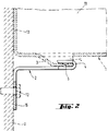
- the fastening part 2 shown in Fig. 2 has a hook 4 and a clamping surface 15, which is penetrated by a passage opening 12.
- a locking element 5 is arranged in the form of a projection, which with a corresponding, schematically illustrated depression or Passage opening in the tab of the holding part can enter into a positive connection.
- the width of the clamping surface 15 is larger than the width of the hook 4 which is matched to the clear cross section of the tab.
- the wall part 21 of the tubular sleeve shown in FIG. 3 also consists of two half-shell-like elements which are pivotally connected to one another via a pivot axis 29 and have radially projecting flanges 26, 27.
- the flanges 26, 27 are braced against one another with the aid of clamping screws 28.
- a plurality of tabs 22, 23 are arranged distributed along the circumference along two circumferential lines.
- the clear widths or cross sections L of the tabs 22, 23 have to each other, but are spaced from each other to enable the insertion of the hook of a fastening part, not shown.
- the tabs 22, 23 have through openings 24, 25, which can form-fit with locking elements on the hook of the fastening parts.
Landscapes
- Engineering & Computer Science (AREA)
- General Engineering & Computer Science (AREA)
- Mechanical Engineering (AREA)
- Supports For Pipes And Cables (AREA)
- Clamps And Clips (AREA)
- Dowels (AREA)
- Joints Allowing Movement (AREA)
- Rigid Pipes And Flexible Pipes (AREA)
- Quick-Acting Or Multi-Walled Pipe Joints (AREA)
- Forms Removed On Construction Sites Or Auxiliary Members Thereof (AREA)
- Separation By Low-Temperature Treatments (AREA)
Applications Claiming Priority (2)
| Application Number | Priority Date | Filing Date | Title |
|---|---|---|---|
| DE4411220A DE4411220A1 (de) | 1994-03-31 | 1994-03-31 | Rohrmanschette |
| DE4411220 | 1994-03-31 |
Publications (2)
| Publication Number | Publication Date |
|---|---|
| EP0675308A1 true EP0675308A1 (fr) | 1995-10-04 |
| EP0675308B1 EP0675308B1 (fr) | 1998-04-08 |
Family
ID=6514331
Family Applications (1)
| Application Number | Title | Priority Date | Filing Date |
|---|---|---|---|
| EP95810016A Expired - Lifetime EP0675308B1 (fr) | 1994-03-31 | 1995-01-10 | Manchon de tuyaux |
Country Status (8)
| Country | Link |
|---|---|
| US (1) | US5586739A (fr) |
| EP (1) | EP0675308B1 (fr) |
| JP (1) | JP3574215B2 (fr) |
| AT (1) | ATE164930T1 (fr) |
| DE (2) | DE4411220A1 (fr) |
| ES (1) | ES2114288T3 (fr) |
| FI (1) | FI106404B (fr) |
| NO (1) | NO951244L (fr) |
Cited By (4)
| Publication number | Priority date | Publication date | Assignee | Title |
|---|---|---|---|---|
| DE19852120A1 (de) * | 1998-08-19 | 2000-03-02 | Friatec Ag | Brandschutzvorrichtung |
| DE102015121031A1 (de) | 2014-12-03 | 2016-06-09 | Uta Kamleithner | Brandschutzeinrichtung |
| US9586066B2 (en) | 2012-10-11 | 2017-03-07 | Hilti Aktiengesellschaft | Fire protection collar |
| DE102021204139A1 (de) | 2021-04-26 | 2022-10-27 | James Hardie Europe Gmbh | Rohrmanschette, Brandschutzmanschette mit derartiger Rohrmanschette, Deckendurchführung, Decke mit derartiger Deckendurchführung und Verfahren zur Montage einer Deckendurchführung |
Families Citing this family (18)
| Publication number | Priority date | Publication date | Assignee | Title |
|---|---|---|---|---|
| TW308613B (en) * | 1996-08-19 | 1997-06-21 | Jyi-Shyang Wang | Manufacturing method and device for carbon fabric absorbent |
| DE19840136A1 (de) * | 1998-09-03 | 2000-03-09 | Volkswagen Ag | Halterungselement und Halterung für starre Leitungen in einem Fahrzeug |
| AUPQ024099A0 (en) | 1999-05-07 | 1999-06-03 | Promat Fyreguard Pty Ltd | Service shut off device |
| US20080035803A1 (en) * | 2006-08-03 | 2008-02-14 | Charles Ingalls | Self-leveling roof utility bucket with second pivotable bottom |
| NL2004318C2 (en) * | 2010-03-01 | 2011-09-05 | Walraven Holding Bv J Van | FIRESTOP COLLAR. |
| USD646763S1 (en) | 2011-02-22 | 2011-10-11 | Hide A Pipe Enclosures, Inc. | Pipe enclosure |
| CA2786194C (fr) * | 2011-09-16 | 2019-01-15 | Hilti Aktiengesellschaft | Manchon de prevention des incendies, utilisation de ce dernier et methode d'installation d'un manchon de prevention des incendies et passage au plafond |
| US8991774B2 (en) * | 2011-12-22 | 2015-03-31 | Panduit Corp. | Cable tie mount |
| DE102011089531A1 (de) * | 2011-12-22 | 2013-06-27 | Hilti Aktiengesellschaft | Brandschutzmanschette |
| EP3088783A1 (fr) | 2015-04-27 | 2016-11-02 | Hilti Aktiengesellschaft | Manchette coupe-feu |
| EP3088784A1 (fr) * | 2015-04-27 | 2016-11-02 | Hilti Aktiengesellschaft | Manchette coupe-feu |
| EP3232105A1 (fr) * | 2016-04-12 | 2017-10-18 | HILTI Aktiengesellschaft | Procede de fabrication d'un module pour un passage de ligne, module et procede de fabrication d'un passage de ligne |
| WO2018178298A1 (fr) * | 2017-03-31 | 2018-10-04 | Promat Australia Pty. Ltd | Collier anti-incendie |
| AU2018246334B2 (en) * | 2017-03-31 | 2023-10-19 | Etex Australia Pty Ltd | Fire-protection collar |
| US11802697B2 (en) * | 2017-12-21 | 2023-10-31 | Roof Goose Vent Llc | Exhaust vent |
| EP3569907B1 (fr) * | 2018-05-15 | 2020-10-07 | Oy FCR Finland Ltd | Dispositif de pénétration |
| WO2021146665A1 (fr) | 2020-01-17 | 2021-07-22 | Simpson Strong-Tie Company Inc. | Installation de coupe-feu au niveau d'une plaque supérieure d'un système d'arrimage |
| DE102022105973A1 (de) | 2022-03-15 | 2023-09-21 | Norma Germany Gmbh | Profilschelle |
Citations (3)
| Publication number | Priority date | Publication date | Assignee | Title |
|---|---|---|---|---|
| US4850385A (en) * | 1988-11-10 | 1989-07-25 | Harbeke Gerold J | Fire stop pipe coupling adaptor |
| GB2233725A (en) * | 1989-07-07 | 1991-01-16 | Arthur Peter Hamilton | Fire stop collar for pipe lead-through |
| EP0486299A1 (fr) * | 1990-11-15 | 1992-05-20 | Minnesota Mining And Manufacturing Company | Dispositif coupe-feu en matériau intumescent |
Family Cites Families (8)
| Publication number | Priority date | Publication date | Assignee | Title |
|---|---|---|---|---|
| US2303108A (en) * | 1941-06-20 | 1942-11-24 | Blackburn Jasper | Cable ring or hanger |
| USRE28035E (en) * | 1973-06-22 | 1974-06-04 | Hold-down means for underploor access housing | |
| US3966155A (en) * | 1975-02-10 | 1976-06-29 | Usm Corporation | Clip for remote control rod |
| US4059872A (en) * | 1975-11-24 | 1977-11-29 | Domenico Delesandri | Hose clamp assembly |
| US4391376A (en) * | 1980-12-15 | 1983-07-05 | Lelasso Corporation | Resilient clamp for supporting articles |
| US4709888A (en) * | 1985-10-01 | 1987-12-01 | T. J. Cope, Inc. | Hanger apparatus for electrical conduit and the like |
| US4903933A (en) * | 1988-07-27 | 1990-02-27 | Yuda Lawrence F | Clamping apparatus for adjustably positioning switches |
| US5261633A (en) * | 1992-12-17 | 1993-11-16 | Mastro Ronald J | Pipe support system |
-
1994
- 1994-03-31 DE DE4411220A patent/DE4411220A1/de not_active Withdrawn
-
1995
- 1995-01-10 AT AT95810016T patent/ATE164930T1/de not_active IP Right Cessation
- 1995-01-10 EP EP95810016A patent/EP0675308B1/fr not_active Expired - Lifetime
- 1995-01-10 DE DE59501811T patent/DE59501811D1/de not_active Expired - Fee Related
- 1995-01-10 ES ES95810016T patent/ES2114288T3/es not_active Expired - Lifetime
- 1995-03-29 FI FI951483A patent/FI106404B/fi not_active IP Right Cessation
- 1995-03-30 NO NO951244A patent/NO951244L/no not_active Application Discontinuation
- 1995-03-31 JP JP07533995A patent/JP3574215B2/ja not_active Expired - Fee Related
- 1995-03-31 US US08/415,016 patent/US5586739A/en not_active Expired - Lifetime
Patent Citations (3)
| Publication number | Priority date | Publication date | Assignee | Title |
|---|---|---|---|---|
| US4850385A (en) * | 1988-11-10 | 1989-07-25 | Harbeke Gerold J | Fire stop pipe coupling adaptor |
| GB2233725A (en) * | 1989-07-07 | 1991-01-16 | Arthur Peter Hamilton | Fire stop collar for pipe lead-through |
| EP0486299A1 (fr) * | 1990-11-15 | 1992-05-20 | Minnesota Mining And Manufacturing Company | Dispositif coupe-feu en matériau intumescent |
Cited By (5)
| Publication number | Priority date | Publication date | Assignee | Title |
|---|---|---|---|---|
| DE19852120A1 (de) * | 1998-08-19 | 2000-03-02 | Friatec Ag | Brandschutzvorrichtung |
| DE19852120C2 (de) * | 1998-08-19 | 2002-12-12 | Friatec Ag | Intumeszierende Brandschutzvorrichtung zum Abschotten von durch Wände oder Decken durchgeführten Rohren |
| US9586066B2 (en) | 2012-10-11 | 2017-03-07 | Hilti Aktiengesellschaft | Fire protection collar |
| DE102015121031A1 (de) | 2014-12-03 | 2016-06-09 | Uta Kamleithner | Brandschutzeinrichtung |
| DE102021204139A1 (de) | 2021-04-26 | 2022-10-27 | James Hardie Europe Gmbh | Rohrmanschette, Brandschutzmanschette mit derartiger Rohrmanschette, Deckendurchführung, Decke mit derartiger Deckendurchführung und Verfahren zur Montage einer Deckendurchführung |
Also Published As
| Publication number | Publication date |
|---|---|
| ATE164930T1 (de) | 1998-04-15 |
| DE59501811D1 (de) | 1998-05-14 |
| ES2114288T3 (es) | 1998-05-16 |
| FI951483L (fi) | 1995-10-01 |
| FI951483A0 (fi) | 1995-03-29 |
| NO951244L (no) | 1995-10-02 |
| EP0675308B1 (fr) | 1998-04-08 |
| DE4411220A1 (de) | 1995-10-05 |
| JP3574215B2 (ja) | 2004-10-06 |
| FI106404B (fi) | 2001-01-31 |
| US5586739A (en) | 1996-12-24 |
| JPH07280138A (ja) | 1995-10-27 |
| NO951244D0 (no) | 1995-03-30 |
Similar Documents
| Publication | Publication Date | Title |
|---|---|---|
| EP0675308A1 (fr) | Manchon de tuyaux | |
| EP0041609A1 (fr) | Dispositif pour la fixation de poignées, accoudoirs et analogues à la paroi de carrosserie d'un véhicule | |
| DE2545181A1 (de) | Zentralisiervorrichtung, vorzugsweise fuer die zentrale fuehrung von rohren, insbesondere der verrohrung von erdbohranlagen | |
| DE69908576T2 (de) | Verbindungsvorrichtung | |
| EP0504097B1 (fr) | Support pour tuyaux ajustable en hauteur | |
| EP0404726B1 (fr) | Dispositif pour la connexion de rails en forme de C, en particulier rails de montage | |
| DE19946042B4 (de) | Rohrschelle | |
| EP1703191A2 (fr) | Raccord de conduits | |
| EP3064849A1 (fr) | Systeme de distribution, en particulier diffuseur d'air | |
| DE3104518A1 (de) | Anschlussarmatur | |
| EP3290764B1 (fr) | Dispositif de retenue pour un objet longitudinal | |
| EP0038872A2 (fr) | Chariot de nettoyage | |
| EP0508300A2 (fr) | Dispositif pour suspendre un ensemble de câbles aériens | |
| EP0667463B1 (fr) | Elément de support en matière plastique, en particulier pour tuyaux | |
| DE102010047991A1 (de) | Befestigungssystem eines Kabelübergangsgerätes in einem Mast | |
| DE10104930A1 (de) | Vorrichtung zur Abdichtung von Mauerdurchführungen | |
| DE3229971C1 (de) | Lösbares Befestigungselement | |
| EP0959536A1 (fr) | Bloc multiprises | |
| DE202006020773U1 (de) | Aufhängeelement | |
| DE29921834U1 (de) | Rohrhalterung für einen Dachrinnenentwässerungsrohrstrang | |
| DE3805257C2 (de) | Aufhängevorrichtung zum Befestigen einer Kabelmuffe an einem Tragseil | |
| EP1439352A1 (fr) | Cache-radiateurs | |
| DE29707971U1 (de) | Verkleidung für einen Flachheizkörper | |
| EP0989310A2 (fr) | Ecrou à positionnement rapide | |
| DE69204441T2 (de) | Verbindungsmanschette und Montageverfahren. |
Legal Events
| Date | Code | Title | Description |
|---|---|---|---|
| PUAI | Public reference made under article 153(3) epc to a published international application that has entered the european phase |
Free format text: ORIGINAL CODE: 0009012 |
|
| AK | Designated contracting states |
Kind code of ref document: A1 Designated state(s): AT CH DE ES FR GB IT LI SE |
|
| 17P | Request for examination filed |
Effective date: 19951023 |
|
| 17Q | First examination report despatched |
Effective date: 19960912 |
|
| GRAG | Despatch of communication of intention to grant |
Free format text: ORIGINAL CODE: EPIDOS AGRA |
|
| GRAG | Despatch of communication of intention to grant |
Free format text: ORIGINAL CODE: EPIDOS AGRA |
|
| GRAH | Despatch of communication of intention to grant a patent |
Free format text: ORIGINAL CODE: EPIDOS IGRA |
|
| GRAH | Despatch of communication of intention to grant a patent |
Free format text: ORIGINAL CODE: EPIDOS IGRA |
|
| GRAA | (expected) grant |
Free format text: ORIGINAL CODE: 0009210 |
|
| ITF | It: translation for a ep patent filed | ||
| AK | Designated contracting states |
Kind code of ref document: B1 Designated state(s): AT CH DE ES FR GB IT LI SE |
|
| REF | Corresponds to: |
Ref document number: 164930 Country of ref document: AT Date of ref document: 19980415 Kind code of ref document: T |
|
| REG | Reference to a national code |
Ref country code: CH Ref legal event code: EP |
|
| REF | Corresponds to: |
Ref document number: 59501811 Country of ref document: DE Date of ref document: 19980514 |
|
| REG | Reference to a national code |
Ref country code: ES Ref legal event code: FG2A Ref document number: 2114288 Country of ref document: ES Kind code of ref document: T3 |
|
| ET | Fr: translation filed | ||
| GBT | Gb: translation of ep patent filed (gb section 77(6)(a)/1977) |
Effective date: 19980611 |
|
| PLBE | No opposition filed within time limit |
Free format text: ORIGINAL CODE: 0009261 |
|
| STAA | Information on the status of an ep patent application or granted ep patent |
Free format text: STATUS: NO OPPOSITION FILED WITHIN TIME LIMIT |
|
| 26N | No opposition filed | ||
| REG | Reference to a national code |
Ref country code: GB Ref legal event code: IF02 |
|
| PGFP | Annual fee paid to national office [announced via postgrant information from national office to epo] |
Ref country code: SE Payment date: 20040107 Year of fee payment: 10 Ref country code: GB Payment date: 20040107 Year of fee payment: 10 |
|
| PGFP | Annual fee paid to national office [announced via postgrant information from national office to epo] |
Ref country code: FR Payment date: 20040108 Year of fee payment: 10 |
|
| PGFP | Annual fee paid to national office [announced via postgrant information from national office to epo] |
Ref country code: AT Payment date: 20040113 Year of fee payment: 10 |
|
| PGFP | Annual fee paid to national office [announced via postgrant information from national office to epo] |
Ref country code: CH Payment date: 20040119 Year of fee payment: 10 |
|
| PGFP | Annual fee paid to national office [announced via postgrant information from national office to epo] |
Ref country code: DE Payment date: 20040122 Year of fee payment: 10 |
|
| PGFP | Annual fee paid to national office [announced via postgrant information from national office to epo] |
Ref country code: ES Payment date: 20040123 Year of fee payment: 10 |
|
| PG25 | Lapsed in a contracting state [announced via postgrant information from national office to epo] |
Ref country code: IT Free format text: LAPSE BECAUSE OF NON-PAYMENT OF DUE FEES;WARNING: LAPSES OF ITALIAN PATENTS WITH EFFECTIVE DATE BEFORE 2007 MAY HAVE OCCURRED AT ANY TIME BEFORE 2007. THE CORRECT EFFECTIVE DATE MAY BE DIFFERENT FROM THE ONE RECORDED. Effective date: 20050110 Ref country code: GB Free format text: LAPSE BECAUSE OF NON-PAYMENT OF DUE FEES Effective date: 20050110 Ref country code: AT Free format text: LAPSE BECAUSE OF NON-PAYMENT OF DUE FEES Effective date: 20050110 |
|
| PG25 | Lapsed in a contracting state [announced via postgrant information from national office to epo] |
Ref country code: SE Free format text: LAPSE BECAUSE OF NON-PAYMENT OF DUE FEES Effective date: 20050111 Ref country code: ES Free format text: LAPSE BECAUSE OF NON-PAYMENT OF DUE FEES Effective date: 20050111 |
|
| PG25 | Lapsed in a contracting state [announced via postgrant information from national office to epo] |
Ref country code: LI Free format text: LAPSE BECAUSE OF NON-PAYMENT OF DUE FEES Effective date: 20050131 Ref country code: CH Free format text: LAPSE BECAUSE OF NON-PAYMENT OF DUE FEES Effective date: 20050131 |
|
| PG25 | Lapsed in a contracting state [announced via postgrant information from national office to epo] |
Ref country code: DE Free format text: LAPSE BECAUSE OF NON-PAYMENT OF DUE FEES Effective date: 20050802 |
|
| EUG | Se: european patent has lapsed | ||
| GBPC | Gb: european patent ceased through non-payment of renewal fee |
Effective date: 20050110 |
|
| REG | Reference to a national code |
Ref country code: CH Ref legal event code: PL |
|
| PG25 | Lapsed in a contracting state [announced via postgrant information from national office to epo] |
Ref country code: FR Free format text: LAPSE BECAUSE OF NON-PAYMENT OF DUE FEES Effective date: 20050930 |
|
| REG | Reference to a national code |
Ref country code: FR Ref legal event code: ST |
|
| REG | Reference to a national code |
Ref country code: ES Ref legal event code: FD2A Effective date: 20050111 |