EP1439352A1 - Cache-radiateurs - Google Patents
Cache-radiateurs Download PDFInfo
- Publication number
- EP1439352A1 EP1439352A1 EP03026302A EP03026302A EP1439352A1 EP 1439352 A1 EP1439352 A1 EP 1439352A1 EP 03026302 A EP03026302 A EP 03026302A EP 03026302 A EP03026302 A EP 03026302A EP 1439352 A1 EP1439352 A1 EP 1439352A1
- Authority
- EP
- European Patent Office
- Prior art keywords
- plastic sleeve
- radiator
- recess
- part according
- cladding part
- Prior art date
- Legal status (The legal status is an assumption and is not a legal conclusion. Google has not performed a legal analysis and makes no representation as to the accuracy of the status listed.)
- Withdrawn
Links
- 238000005253 cladding Methods 0.000 claims abstract description 23
- 230000001154 acute effect Effects 0.000 claims description 3
- 238000003780 insertion Methods 0.000 claims description 3
- 230000037431 insertion Effects 0.000 claims description 3
- 239000002184 metal Substances 0.000 abstract 1
- 238000009423 ventilation Methods 0.000 abstract 1
- 238000006073 displacement reaction Methods 0.000 description 6
- 238000004519 manufacturing process Methods 0.000 description 4
- 239000000463 material Substances 0.000 description 3
- 238000000034 method Methods 0.000 description 3
- 238000005520 cutting process Methods 0.000 description 2
- 238000013461 design Methods 0.000 description 2
- 230000001419 dependent effect Effects 0.000 description 1
- 230000001066 destructive effect Effects 0.000 description 1
- 238000011161 development Methods 0.000 description 1
- 230000000694 effects Effects 0.000 description 1
- 238000005516 engineering process Methods 0.000 description 1
- 238000001746 injection moulding Methods 0.000 description 1
- 238000009434 installation Methods 0.000 description 1
- 230000008520 organization Effects 0.000 description 1
- 230000000630 rising effect Effects 0.000 description 1
- 238000012549 training Methods 0.000 description 1
- 230000000007 visual effect Effects 0.000 description 1
Images




Classifications
-
- F—MECHANICAL ENGINEERING; LIGHTING; HEATING; WEAPONS; BLASTING
- F24—HEATING; RANGES; VENTILATING
- F24D—DOMESTIC- OR SPACE-HEATING SYSTEMS, e.g. CENTRAL HEATING SYSTEMS; DOMESTIC HOT-WATER SUPPLY SYSTEMS; ELEMENTS OR COMPONENTS THEREFOR
- F24D19/00—Details
- F24D19/06—Casings, cover lids or ornamental panels, for radiators
- F24D19/065—Grids attached to the radiator and covering its top
-
- F—MECHANICAL ENGINEERING; LIGHTING; HEATING; WEAPONS; BLASTING
- F24—HEATING; RANGES; VENTILATING
- F24D—DOMESTIC- OR SPACE-HEATING SYSTEMS, e.g. CENTRAL HEATING SYSTEMS; DOMESTIC HOT-WATER SUPPLY SYSTEMS; ELEMENTS OR COMPONENTS THEREFOR
- F24D19/00—Details
- F24D19/06—Casings, cover lids or ornamental panels, for radiators
Definitions
- the divisional application contains an independent claim 1 in terms of content of the former Claim 5 corresponds to the parent application. Close independent claim 1 itself 10 dependent claims 2 to 11. These correspond to the original ones Claims 6 to 15 of the parent application.
- the priority document is in the file of the parent application.
- the invention relates to a side panel of a radiator, which has an end face of the radiator covers, at least one recess for performing a Has connecting cable and detachable with the help of fasteners with the radiator is connectable, the fastening means being formed by at least one plastic sleeve are the axially up to a radially outwardly projecting stop flange in one Part-circular section of the recess can be inserted and with edge areas of the Recess in an adapted, in the insertion direction in front of the stop flange engage arranged recess, can be locked such that one of the stop flange facing soffit of the recess the edge areas in the assembled state of the Plastic sleeve engages behind, the longitudinal axis of a pipe socket for the Connection line runs perpendicular to the side panel and the pipe socket is provided with a radially outwardly projecting retaining flange, which with at least a radially inwardly projecting over the inner surface of the plastic s
- Claddings for radiators are widespread and in known many different training courses. Such claddings find one increasingly widespread, as the demands on the visual appearance of a Radiator constantly rising.
- a side trim part of the type described in the opening paragraph is, for example, from DE 297 07 971 U1 known.
- the plastic sleeve used to attach it has closed in a ring and laterally for the purpose of attacking a key flattened flange part on that on the visible side of the trim part Border areas around the recess for the connecting line.
- the plastic sleeve with the trim part in a first step, the from the aforementioned parts unit formed from below in the vertical direction on the pipe socket pushed on for the connecting cable.
- a holding section is the Provide plastic sleeve with radially inward projecting snap hooks, which in when fitted, grasp a retaining flange of the pipe socket.
- the plastic sleeve also has the function create a connection between the side and an upper trim part.
- the plastic sleeve is on its stop flange with a pin-shaped Latch provided, which in the assembled state in an adapted hole in one angled edge strips of the upper trim part engages.
- a disadvantage of the known trim part is that it is not in horizontal direction to the radiator and disassembled from it can be.
- the assembly and disassembly is complicated, among other things, by the fact that in addition to the connection between the plastic sleeve and the pipe socket Connection between the catch of the plastic sleeve and the upper panel must be manufactured.
- a disadvantage of such a panel appears that due to the installation in Form of a longitudinal displacement connecting the side panel to an upper one Cladding with hook-shaped tabs is not possible.
- EP 0 480 184 A1 describes a multi-panel radiator in which the spacing held radiator panels in the upper area connected by T-shaped connectors and for the lateral covering of the space between the panels, side parts on the connecting pieces are held.
- the connectors equipped with a collar are through a corresponding opening in the side part accessible.
- a plastic sleeve which can be fastened to the connecting piece is provided, onto which one can be screwed on through the coaxial opening in the side panel or can be plugged on and locked.
- the collar sleeve lies with its outer collar on the Side part and thereby prevents its removal from the radiator.
- DE 297 10 290 U1 discloses for fastening the side covering part on the radiator in the area of the connecting piece also a plastic ring, the one has in the longitudinal direction plug-in opening, by means of which it is on the Has the connection section of the T-shaped connection pipe piece attached. That the The end of the plastic ring facing the connecting pipe piece is trumpet-shaped bent up, this end due to its material elastic properties for the Fixing effect is decisive.
- the invention has for its object a side panel part to propose radiator cladding that is inexpensive to manufacture and easy to assemble leaves, whereby the possibility of non-destructive disassembly should also be created. Furthermore, the cladding should also meet the increased aesthetic requirements become.
- the object on which the invention is based is achieved by a lateral covering part Radiator solved, in which the plastic sleeve is provided with a longitudinal slot and that lateral trim part together with the plastic sleeve essentially in axial Direction of the same can be pushed onto the pipe socket for the connecting line.
- a great advantage of the side trim part according to the invention can be seen in the fact that the assembly of the same in vertical after the pre-assembly of the plastic sleeve Direction to the level of this trim part can be done.
- the plastic sleeve slides thereby in the axial direction of the pipe socket with the snap hooks projecting inwards over the retaining flange of the pipe socket, which is due to the elasticity of the Plastic material can expand in connection with its longitudinal slot. After a Passage of the holding flange takes the plastic sleeve back to its original Diameter, with the end faces of the snap hook engaging behind the holding flange and therefore ensure a positive connection in the axial direction of the pipe socket.
- An embodiment of the side trim part according to the invention is that the plastic sleeve several snap hooks are provided with their the radiator facing end faces offset from each other in the axial direction of the plastic sleeve are arranged.
- two snap hooks be made in one piece Shoot at the inner surface of the plastic sleeve and adjoin the Extend the longitudinal slot over an angular range of 45 ° to 180 °.
- Such an embodiment offers the advantage that the inner jacket surface subsequent snap hooks are particularly easy to manufacture using injection molding technology.
- a snap hook is connected exclusively via one of the engaging ones Front facing away web is integrally connected to the plastic sleeve and with the Longitudinal axis of the plastic sleeve encloses an angle of 10 ° to 40 °.
- Such a design of the snap hook is particularly suitable for one in axial Arrangement shifted towards the center of the plastic sleeve.
- the snap hook is provided with an end section is that projects beyond the rear end face and resiliently on an outer surface of the holding flange of the pipe socket.
- the one behind End faces opposite sides of the snap hook, starting from the inner one Mantle surface of the plastic sleeve, ramp up, causing the assembly process is simplified.
- annular groove-shaped recess in the plastic sleeve one from its bottom has outgoing increase in the assembled state of the plastic sleeve in the side panel with an adapted recess in the edge areas of the Corresponding recess is always a correct alignment of the plastic sleeve guaranteed.
- stop flange the plastic sleeve in an end segment adjacent to the longitudinal slot under one acute angle to the remaining plane of the stop flange inclined towards the Radiator runs and the end segment in the assembled state of the plastic sleeve is located in an area of the recess that is opposite to that which locks in the recess Edge areas radially outwards at least to the outside diameter of the Stop flange is expanded.
- the plastic sleeve adjoins the radiator facing end face with at least two arranged on its inner lateral surface and attack cams projecting radially inwards is provided.
- Attack cams of this type can be used as a stop for with or adapted recesses Serve with pins provided.
- the lining of a radiator, not shown, shown in Figure 1 consists of an upper panel 1 and a side panel 2, which are rectangular are arranged to each other. That with a plurality of through openings 3 for heated Air-provided upper trim part 1 covers the top of the radiator while the each end with a recess 4 and 5 provided side panel 2 for Covering one end of the radiator is used.
- the upper trim part 1 is next to the Edge strip 7, which lies in one plane with the side trim part 2, also with an adjoining one and 90 ° in the direction of the passage openings 3 bent back edge strips 11 provided.
- edge strip 11 With this edge strip 11 are again integrally connected four U-shaped tabs 12, which are in areas below the Edge strip 11 extend.
- the tabs 12 of the upper trim part 1 follow in a U-shape are angled outside and with a lower leg 13 a support for the Form edge strips 9 of the side trim part 2.
- An end face 14 of the leg 13 the flap 12 lies approximately parallel to the side trim part 2 aligned end portion 15 of the tab 10 in a plane which is the plane of the Radiator facing side 16 of the side trim part 2 and the Passage openings 3 facing side 17 of the edge strip 7 of the upper Cover part 1 is.
- the contact areas of the tabs 10 and 12 are thus in one Level that with respect to the side facing away from the radiator 18 of the lateral Cover part 2 is set back by the sheet thickness.
- FIG. 4 shows that two upper tabs 12 each have a lower tab 10 frame, causing a lateral displacement of the two trim parts 1 and 2 to each other is prevented. It can be seen that the available contact length of the two trim parts 1 and 2 either through a tab 10 or a tab 12 is occupied in order to achieve a stable connection.
- Figure 5 shows that the trim parts 1 and 2 inclined at an angle ⁇ of 30 ° must be approached to one another, the edge strip 9 according to FIG. 6 of the side trim part 2 is inserted into the groove formed by the tab 12.
- Figure 6 shows the trim parts 1 and 2 in a parallel shifted cutting plane, in which is an upper tab 12, but not a lower tab 10, but only the edge strip 9 located.
- Figure 7 shows the two trim parts 1 and 2 still inclined to each other Arrangement, the tabs 10 of the side trim part 2 already the edge strip 11 of the upper trim part 1 have included.
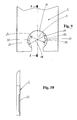
- Figure 9 shows that the lower recess 5 of the side trim part 2 opposite sides is provided with edge regions 20 and 21, the edges 22 and 23 lie on a common circle. Between the two edge areas 20 and 21 there is an area 24 with an enlarged diameter. In this area 24 there is Diameter 25 slightly larger than the diameter 26 shown in FIG insertable plastic sleeve 27.
- edge regions 20 and 21 are opposite the surrounding surface of the side trim part 2 arranged recessed. This Recess of the edge areas 20 and 21 serves to accommodate one in its width correspondingly adapted stop flange 29 to be inserted into the recess 5 Plastic sleeve 27.
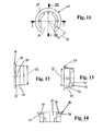
- the structure of the plastic sleeve 27 is shown in more detail in FIGS. 11 to 18 explains:
- the plastic sleeve 27 has a longitudinal slot 28 which is shown in FIG its width is adapted to a connection line, not shown, to which the Plastic sleeve 27 must be pushed.
- the plastic sleeve 27 has an end face arranged stop flange 29, to which a recess 30 in the form of a groove followed.
- the outer diameter of the plastic sleeve 27 goes back to a diameter 32, which is slightly smaller than the diameter 33 of a part-circular and of the Edge strips 20 and 21 limited portion of the recess 5. That way insert the plastic sleeve 27 into the recess 5 without resistance.
- FIG. 14 also shows that the stop flange 29 is connected to the Longitudinal slot 28 adjacent end segment 36 (see FIG. 11) at an acute angle the remaining plane of the stop flange 29 inclined towards the side Cover part 2 or the radiator is running.
- the end segment 36 is in the assembled state of the plastic sleeve 27 in the enlarged area 24 of the recess 5 and therefore does not prevent the edge regions 20, 21 from engaging in the groove-shaped there circumferential depression 30.
- FIGS. 1 to 4 and 8 The assembled position of the plastic sleeve 27 can be seen in FIGS. 1 to 4 and 8. From Figure 8 it is clear that the stop flange 29 is flush with the side Closes part 2 and that the edge area 20 engages in the recess 30, whereby an axial sliding out of the plastic sleeve 27 is prevented.
- Figure 15 shows the arrangement of five snap hooks 37, 38 and 39, which radially over the protrude inner lateral surface 40 of the plastic sleeve 27.
- two snap hooks 37 are integral with the inner one Shaped surface 40 formed and extend - adjacent to the longitudinal slot 28 - over an angular range of approximately 180 ° (see FIG. 11).
- These snap hooks 37 have a conical shape extending surface 41 and an opposite perpendicular to the longitudinal axis L of the Plastic sleeve 27 extending end face 42. Because of the conical surface 41 Sliding on the plastic sleeve 27 via a holding flange 43 on a pipe socket 44 relieved, while a due to the perpendicular to the longitudinal axis end face 42 Pulling off the sleeve from the pipe socket 44 is prevented (see FIG. 3). The Outer diameter 43 'of the holding flange 43 is less than the inner diameter 32' of the Plastic sleeve 27 in the area behind the snap hook 37.
- the plastic sleeve 27 has three further snap hooks 38 and 39 which are only connected to the plastic sleeve 27 via a web 45.
- the web 45 is located on the side of the snap hooks 38, 39, the end face 46, which is supported on the holding flange 43 of the pipe socket 44, faces away.
- the Snap hooks 38 and 39 are thus each within a "window" in the jacket Plastic sleeve 27 arranged and close with its longitudinal axis L an angle of approximately 20 ° on.
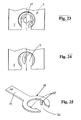
- FIGS. 16 to 18 show that the plastic sleeve 27 is adjacent to the End face 47 facing away from pipe socket 44 with three on its inner lateral surface 40 arranged and radially inwardly projecting engagement cam 48 is provided. Adjacent spacing cams are offset by 90 ° to each other. Between these Attack cam 48 and a key-shaped tool 49, which is shown in FIG. 25, a positive fit can be produced, which causes the plastic sleeve 27 to rotate about it Longitudinal axis allowed.
- the tool 49 is offset by two by 180 ° arranged and axially projecting pins 50 are provided. To the tool 49 To be able to push over a connecting line to be connected to the pipe socket 44 this is provided with a slot 52 on a side opposite a handle 51.
- FIGS. 19 to 24 show how the side cladding part 2 latched plastic sleeve 27 can be removed by twisting.
- a of the tool 49 executed rotary movement namely grips the inclined End segment 36 of the stop flange 29 behind a bevelled end face of the edge region 20, so that the groove-shaped recess 30 comes out of engagement with this edge region 20.
- the Positive locking can be completed by continued rotation of the plastic sleeve 27 be lifted so that the side panel 2 from the still with the Retaining flange 43 of the pipe socket 44 connected plastic sleeve 27 are withdrawn can. Due to the opening 5 on the front side, it occurs when the side panel 2 around the articulated connection to the upper panel 1 for no collision with the connecting cable.
- the plastic sleeve 27 remaining isolated on the pipe socket 44 can be removed after removal of the side trim part 2 due to their material-elastic properties easily remove widening from the holding flange 43.
Landscapes
- Engineering & Computer Science (AREA)
- Physics & Mathematics (AREA)
- Thermal Sciences (AREA)
- Chemical & Material Sciences (AREA)
- Combustion & Propulsion (AREA)
- Mechanical Engineering (AREA)
- General Engineering & Computer Science (AREA)
- Connection Of Plates (AREA)
- Cold Cathode And The Manufacture (AREA)
- Led Device Packages (AREA)
- Cooling, Air Intake And Gas Exhaust, And Fuel Tank Arrangements In Propulsion Units (AREA)
- Domestic Hot-Water Supply Systems And Details Of Heating Systems (AREA)
- Lining Or Joining Of Plastics Or The Like (AREA)
- Finger-Pressure Massage (AREA)
- Cathode-Ray Tubes And Fluorescent Screens For Display (AREA)
- Overhead Projectors And Projection Screens (AREA)
- Resistance Heating (AREA)
- Cookers (AREA)
- Thermotherapy And Cooling Therapy Devices (AREA)
- Housings, Intake/Discharge, And Installation Of Fluid Heaters (AREA)
- Insertion Pins And Rivets (AREA)
Applications Claiming Priority (3)
| Application Number | Priority Date | Filing Date | Title |
|---|---|---|---|
| DE29801129U DE29801129U1 (de) | 1998-01-23 | 1998-01-23 | Heizkörperverkleidung |
| DE29801129U | 1998-01-23 | ||
| EP99100151A EP0931987B1 (fr) | 1998-01-23 | 1999-01-07 | Cache-radiateurs |
Related Parent Applications (1)
| Application Number | Title | Priority Date | Filing Date |
|---|---|---|---|
| EP99100151A Division EP0931987B1 (fr) | 1998-01-23 | 1999-01-07 | Cache-radiateurs |
Publications (1)
| Publication Number | Publication Date |
|---|---|
| EP1439352A1 true EP1439352A1 (fr) | 2004-07-21 |
Family
ID=8051662
Family Applications (2)
| Application Number | Title | Priority Date | Filing Date |
|---|---|---|---|
| EP99100151A Expired - Lifetime EP0931987B1 (fr) | 1998-01-23 | 1999-01-07 | Cache-radiateurs |
| EP03026302A Withdrawn EP1439352A1 (fr) | 1998-01-23 | 1999-01-07 | Cache-radiateurs |
Family Applications Before (1)
| Application Number | Title | Priority Date | Filing Date |
|---|---|---|---|
| EP99100151A Expired - Lifetime EP0931987B1 (fr) | 1998-01-23 | 1999-01-07 | Cache-radiateurs |
Country Status (7)
| Country | Link |
|---|---|
| EP (2) | EP0931987B1 (fr) |
| AT (1) | ATE287069T1 (fr) |
| CZ (1) | CZ298344B6 (fr) |
| DE (3) | DE29801129U1 (fr) |
| PL (1) | PL195607B1 (fr) |
| SK (1) | SK286321B6 (fr) |
| TR (1) | TR199802725A2 (fr) |
Cited By (1)
| Publication number | Priority date | Publication date | Assignee | Title |
|---|---|---|---|---|
| EP1655545A3 (fr) * | 2004-11-03 | 2010-11-03 | BSH Bosch und Siemens Hausgeräte GmbH | Radiateur avec couvercle |
Families Citing this family (3)
| Publication number | Priority date | Publication date | Assignee | Title |
|---|---|---|---|---|
| DE29817420U1 (de) * | 1998-09-29 | 1999-01-28 | Kermi Gmbh, 94447 Plattling | Befestigungseinrichtung bzw. Anordnung mit dieser |
| FR3035955B1 (fr) * | 2015-05-06 | 2019-04-19 | Valeo Systemes Thermiques | Echangeur de chaleur comportant un dispositif de protection |
| CN117823987B (zh) * | 2024-01-02 | 2024-08-27 | 缙云县盛大实业有限公司 | 一种可拆卸钢板散热器结构 |
Citations (2)
| Publication number | Priority date | Publication date | Assignee | Title |
|---|---|---|---|---|
| DE29604834U1 (de) * | 1996-03-15 | 1996-05-09 | Ulamo Beheer B.V., Ulft | Randabdeckung für Flachheizkörper |
| DE29707971U1 (de) * | 1997-05-02 | 1997-06-26 | Paul Edelhoff GmbH & Co. KG, 58638 Iserlohn | Verkleidung für einen Flachheizkörper |
Family Cites Families (9)
| Publication number | Priority date | Publication date | Assignee | Title |
|---|---|---|---|---|
| DE8902961U1 (de) * | 1989-03-10 | 1989-05-11 | Kermi GmbH, 8350 Plattling | Heizkörperverkleidung |
| DE8904646U1 (de) * | 1989-04-13 | 1989-05-24 | Fa. Kurt Wiemann, 5870 Hemer | Blende zur seitlichen Verkleidung von Flachheizkörpern |
| DE8912436U1 (de) * | 1989-10-20 | 1989-12-07 | Paul Edelhoff KG, 5860 Iserlohn | Verkleidung für einen Plattenheizkörper |
| DE4023548A1 (de) * | 1990-07-25 | 1992-02-06 | Ulamo Beheer Bv | Abdeckplatte fuer die seitenraender von flachheizkoerpern |
| DE9014178U1 (de) * | 1990-10-12 | 1990-12-20 | Fa. Wolfgang Förster, 5870 Hemer | Mehrplattenheizkörper |
| DE29505238U1 (de) * | 1995-03-28 | 1995-06-01 | Paul Edelhoff KG, 58638 Iserlohn | Verkleidung für einen Plattenheizkörper |
| DE29607615U1 (de) * | 1996-04-26 | 1996-07-11 | Förster, Wolfgang, 58675 Hemer | Mehrplattenheizkörper |
| DE29707969U1 (de) * | 1997-05-02 | 1997-07-03 | Paul Edelhoff GmbH & Co. KG, 58638 Iserlohn | Verkleidung für einen Flachheizkörper |
| DE29710290U1 (de) * | 1997-06-12 | 1997-08-07 | Paul Edelhoff GmbH & Co. KG, 58638 Iserlohn | Verkleidung für einen Flachheizkörper |
-
1998
- 1998-01-23 DE DE29801129U patent/DE29801129U1/de not_active Expired - Lifetime
- 1998-05-13 DE DE19821421A patent/DE19821421B4/de not_active Expired - Lifetime
- 1998-12-28 TR TR1998/02725A patent/TR199802725A2/xx unknown
-
1999
- 1999-01-07 AT AT99100151T patent/ATE287069T1/de active
- 1999-01-07 DE DE59911418T patent/DE59911418D1/de not_active Expired - Lifetime
- 1999-01-07 EP EP99100151A patent/EP0931987B1/fr not_active Expired - Lifetime
- 1999-01-07 EP EP03026302A patent/EP1439352A1/fr not_active Withdrawn
- 1999-01-15 SK SK58-99A patent/SK286321B6/sk not_active IP Right Cessation
- 1999-01-20 CZ CZ0019599A patent/CZ298344B6/cs not_active IP Right Cessation
- 1999-01-20 PL PL330951A patent/PL195607B1/pl unknown
Patent Citations (2)
| Publication number | Priority date | Publication date | Assignee | Title |
|---|---|---|---|---|
| DE29604834U1 (de) * | 1996-03-15 | 1996-05-09 | Ulamo Beheer B.V., Ulft | Randabdeckung für Flachheizkörper |
| DE29707971U1 (de) * | 1997-05-02 | 1997-06-26 | Paul Edelhoff GmbH & Co. KG, 58638 Iserlohn | Verkleidung für einen Flachheizkörper |
Cited By (1)
| Publication number | Priority date | Publication date | Assignee | Title |
|---|---|---|---|---|
| EP1655545A3 (fr) * | 2004-11-03 | 2010-11-03 | BSH Bosch und Siemens Hausgeräte GmbH | Radiateur avec couvercle |
Also Published As
| Publication number | Publication date |
|---|---|
| DE59911418D1 (de) | 2005-02-17 |
| SK5899A3 (en) | 2000-03-13 |
| PL195607B1 (pl) | 2007-10-31 |
| EP0931987B1 (fr) | 2005-01-12 |
| SK286321B6 (en) | 2008-07-07 |
| DE19821421B4 (de) | 2004-04-08 |
| EP0931987A2 (fr) | 1999-07-28 |
| ATE287069T1 (de) | 2005-01-15 |
| TR199802725A2 (xx) | 1999-08-23 |
| CZ298344B6 (cs) | 2007-09-05 |
| EP0931987A3 (fr) | 2001-11-21 |
| DE19821421A1 (de) | 1999-07-29 |
| PL330951A1 (en) | 1999-08-02 |
| CZ19599A3 (cs) | 1999-08-11 |
| DE29801129U1 (de) | 1998-03-26 |
Similar Documents
| Publication | Publication Date | Title |
|---|---|---|
| DE69001265T2 (de) | Verschlussring fuer gewellte rohre. | |
| AT509796B1 (de) | Hohlprofil | |
| EP3612698B1 (fr) | Charnière pour boîtier d'armoire de commande ainsi que boîtier d'armoire de commande et procédé de montage correspondants | |
| DE2556459C2 (de) | Schwenkvorrichtung | |
| DE102017117002A1 (de) | Vorrichtung zum Befestigen eines Bauteils an einem Trägerbauteil | |
| EP0137969A2 (fr) | Store à rouleau dont les éléments de fixation portent la boîte par les côtés frontaux | |
| EP3472904B1 (fr) | Ensemble de charnière pour une armoire electrique | |
| EP0675308A1 (fr) | Manchon de tuyaux | |
| EP1516402A1 (fr) | Attache de cable | |
| EP0562499B1 (fr) | Profilé pour canalisation de câbles | |
| EP1439352A1 (fr) | Cache-radiateurs | |
| DE2056723B2 (de) | Befestigungsvorrichtung an einem Türschild mit Handhabenlagerungsbohrang | |
| EP2333433B1 (fr) | Support pour un corps de chauffage de plaques et système de support | |
| EP4097320B1 (fr) | Charnière | |
| DE29924835U1 (de) | Heizkörperverkleidung | |
| EP0898919B1 (fr) | Elément de réglage pour dispositif de douche ou équivalent | |
| EP3029244B1 (fr) | Dispositif de recouvrement pour un raccord | |
| EP0936410B1 (fr) | Plaque de cuisson encastrable avec moyens de fixation | |
| EP0672463A1 (fr) | Rouleau à peindre | |
| EP0995867B1 (fr) | Armoire de distribution électrique avec dispositif de fermeture à barre | |
| DE102019209409A1 (de) | Abdeckhaube für einen tür- oder fensterantrieb | |
| EP0696098A1 (fr) | Dispositif de couplage pour canalisations de guidage de câbles | |
| EP0430271B1 (fr) | Grille de plafond suspendu | |
| EP0974791A2 (fr) | Revêtement pour radiateur à plaques avec élément d'actionnement externe | |
| CH568466A5 (en) | Sky light of man-made material - has wing hinged to frame on either side swivelling around axis |
Legal Events
| Date | Code | Title | Description |
|---|---|---|---|
| PUAI | Public reference made under article 153(3) epc to a published international application that has entered the european phase |
Free format text: ORIGINAL CODE: 0009012 |
|
| AC | Divisional application: reference to earlier application |
Ref document number: 0931987 Country of ref document: EP Kind code of ref document: P |
|
| AK | Designated contracting states |
Kind code of ref document: A1 Designated state(s): AT BE CH CY DE DK ES FI FR GB GR IE IT LI LU MC NL PT SE |
|
| 17P | Request for examination filed |
Effective date: 20041020 |
|
| AKX | Designation fees paid |
Designated state(s): AT BE CH CY DE DK ES FI FR GB GR IE IT LI LU MC NL PT SE |
|
| GRAP | Despatch of communication of intention to grant a patent |
Free format text: ORIGINAL CODE: EPIDOSNIGR1 |
|
| STAA | Information on the status of an ep patent application or granted ep patent |
Free format text: STATUS: THE APPLICATION IS DEEMED TO BE WITHDRAWN |
|
| 18D | Application deemed to be withdrawn |
Effective date: 20060322 |