EP0675325A1 - Procédé et dispositif de commande de combustion des brûleurs dans un four - Google Patents
Procédé et dispositif de commande de combustion des brûleurs dans un four Download PDFInfo
- Publication number
- EP0675325A1 EP0675325A1 EP95302046A EP95302046A EP0675325A1 EP 0675325 A1 EP0675325 A1 EP 0675325A1 EP 95302046 A EP95302046 A EP 95302046A EP 95302046 A EP95302046 A EP 95302046A EP 0675325 A1 EP0675325 A1 EP 0675325A1
- Authority
- EP
- European Patent Office
- Prior art keywords
- combustion
- burner
- burners
- temperature
- controlling
- Prior art date
- Legal status (The legal status is an assumption and is not a legal conclusion. Google has not performed a legal analysis and makes no representation as to the accuracy of the status listed.)
- Granted
Links
- 238000002485 combustion reaction Methods 0.000 title claims abstract description 73
- 238000000034 method Methods 0.000 title claims abstract description 33
- 239000002737 fuel gas Substances 0.000 claims description 6
- 230000000694 effects Effects 0.000 claims description 3
- 239000000446 fuel Substances 0.000 claims description 3
- 238000010304 firing Methods 0.000 description 2
- 238000013459 approach Methods 0.000 description 1
- 239000000919 ceramic Substances 0.000 description 1
- 239000000567 combustion gas Substances 0.000 description 1
- 230000001351 cycling effect Effects 0.000 description 1
- 230000002542 deteriorative effect Effects 0.000 description 1
- 238000010586 diagram Methods 0.000 description 1
- 230000003292 diminished effect Effects 0.000 description 1
- 238000012986 modification Methods 0.000 description 1
- 230000004048 modification Effects 0.000 description 1
Images


Classifications
-
- F—MECHANICAL ENGINEERING; LIGHTING; HEATING; WEAPONS; BLASTING
- F27—FURNACES; KILNS; OVENS; RETORTS
- F27D—DETAILS OR ACCESSORIES OF FURNACES, KILNS, OVENS OR RETORTS, IN SO FAR AS THEY ARE OF KINDS OCCURRING IN MORE THAN ONE KIND OF FURNACE
- F27D19/00—Arrangements of controlling devices
-
- F—MECHANICAL ENGINEERING; LIGHTING; HEATING; WEAPONS; BLASTING
- F23—COMBUSTION APPARATUS; COMBUSTION PROCESSES
- F23N—REGULATING OR CONTROLLING COMBUSTION
- F23N1/00—Regulating fuel supply
- F23N1/02—Regulating fuel supply conjointly with air supply
- F23N1/022—Regulating fuel supply conjointly with air supply using electronic means
-
- F—MECHANICAL ENGINEERING; LIGHTING; HEATING; WEAPONS; BLASTING
- F23—COMBUSTION APPARATUS; COMBUSTION PROCESSES
- F23N—REGULATING OR CONTROLLING COMBUSTION
- F23N5/00—Systems for controlling combustion
- F23N5/02—Systems for controlling combustion using devices responsive to thermal changes or to thermal expansion of a medium
- F23N5/022—Systems for controlling combustion using devices responsive to thermal changes or to thermal expansion of a medium using electronic means
-
- G—PHYSICS
- G05—CONTROLLING; REGULATING
- G05D—SYSTEMS FOR CONTROLLING OR REGULATING NON-ELECTRIC VARIABLES
- G05D23/00—Control of temperature
- G05D23/19—Control of temperature characterised by the use of electric means
- G05D23/1906—Control of temperature characterised by the use of electric means using an analogue comparing device
- G05D23/1913—Control of temperature characterised by the use of electric means using an analogue comparing device delivering a series of pulses
-
- F—MECHANICAL ENGINEERING; LIGHTING; HEATING; WEAPONS; BLASTING
- F23—COMBUSTION APPARATUS; COMBUSTION PROCESSES
- F23N—REGULATING OR CONTROLLING COMBUSTION
- F23N2223/00—Signal processing; Details thereof
- F23N2223/08—Microprocessor; Microcomputer
-
- F—MECHANICAL ENGINEERING; LIGHTING; HEATING; WEAPONS; BLASTING
- F23—COMBUSTION APPARATUS; COMBUSTION PROCESSES
- F23N—REGULATING OR CONTROLLING COMBUSTION
- F23N2227/00—Ignition or checking
- F23N2227/10—Sequential burner running
-
- F—MECHANICAL ENGINEERING; LIGHTING; HEATING; WEAPONS; BLASTING
- F23—COMBUSTION APPARATUS; COMBUSTION PROCESSES
- F23N—REGULATING OR CONTROLLING COMBUSTION
- F23N2237/00—Controlling
- F23N2237/02—Controlling two or more burners
-
- F—MECHANICAL ENGINEERING; LIGHTING; HEATING; WEAPONS; BLASTING
- F27—FURNACES; KILNS; OVENS; RETORTS
- F27D—DETAILS OR ACCESSORIES OF FURNACES, KILNS, OVENS OR RETORTS, IN SO FAR AS THEY ARE OF KINDS OCCURRING IN MORE THAN ONE KIND OF FURNACE
- F27D19/00—Arrangements of controlling devices
- F27D2019/0006—Monitoring the characteristics (composition, quantities, temperature, pressure) of at least one of the gases of the kiln atmosphere and using it as a controlling value
- F27D2019/0018—Monitoring the temperature of the atmosphere of the kiln
-
- F—MECHANICAL ENGINEERING; LIGHTING; HEATING; WEAPONS; BLASTING
- F27—FURNACES; KILNS; OVENS; RETORTS
- F27D—DETAILS OR ACCESSORIES OF FURNACES, KILNS, OVENS OR RETORTS, IN SO FAR AS THEY ARE OF KINDS OCCURRING IN MORE THAN ONE KIND OF FURNACE
- F27D19/00—Arrangements of controlling devices
- F27D2019/0028—Regulation
- F27D2019/0034—Regulation through control of a heating quantity such as fuel, oxidant or intensity of current
- F27D2019/004—Fuel quantity
-
- F—MECHANICAL ENGINEERING; LIGHTING; HEATING; WEAPONS; BLASTING
- F27—FURNACES; KILNS; OVENS; RETORTS
- F27D—DETAILS OR ACCESSORIES OF FURNACES, KILNS, OVENS OR RETORTS, IN SO FAR AS THEY ARE OF KINDS OCCURRING IN MORE THAN ONE KIND OF FURNACE
- F27D99/00—Subject matter not provided for in other groups of this subclass
- F27D99/0001—Heating elements or systems
- F27D99/0033—Heating elements or systems using burners
- F27D2099/0043—Impulse burner
Definitions
- the present invention relates to a process for controlling combustion of burners attached to a furnace such as a firing kiln and an apparatus therefor.
- a burner combustion-controlling process which can control the temperature inside the furnace without throttling the combustion output through each of the burners.
- the interior of the furnace is divided into a plurality of control zones, burners are arranged in the respective control zones, and successively subjected to combustion for a short time, while the control zones are successively employed as a combustion zone, and such a combustion cycle is repeated.
- Fig. 6 shows this process in the form of a time chart.
- the interior of the furnace is divided into three control zones at upper, middle and lower stages.
- the upper stage burner is subjected to combustion for first 6 seconds, then the middle stage burner is subjected to combustion for next 6 seconds, and the lower stage burner is thereafter subjected to combustion for succeeding 6 seconds.
- This cycle is repeated. Since each burner is subjected to combustion, although intermittently, without throttling its combustion output, this process has an advantage in that a large amount of air need not be fed inside the furnace. Further, the amount of generated heat through all the burners can be controlled by adjusting a time period from a point of time at which combustion through a certain stage burner is stopped to a point of time at which combustion is succeedingly started through another stage burner.
- a first aspect of the burner combustion-controlling process of the present invention is characterized in that the interior of the furnace is divided into a plurality of control zones, at least one burner is arranged in each control zone and successively subjected to combustion for a short time, and this cycle is repeated, wherein at least one temperature sensor is fitted in each control zone, a time period during which combustion is effected through each burner is adjusted depending upon a difference between a temperature detected by the temperature sensor and a preset temperature in a respective control zone.
- a second aspect of the burner combustion-controlling process of the present invention is characterized in that the interior of the furnace is divided into a plurality of control zones, at least one burner is arranged in each control zone and successively subjected to combustion for a short time, and this cycle is repeated, wherein at least one temperature sensor is fitted in each control zone, a time period during which combustion is effected through each burner is adjusted depending upon a difference between a temperature detected by the temperature sensor and a preset temperature, and if a detected temperature of a certain zone exceeds a preset temperature, combustion is skipped for the burner in said certain zone for a given time period during which said burner is to be subjected to combustion.
- the burner combustion-controlling apparatus is adapted to control combustion through burners attached to a plurality of respective control zones that are defined by dividing an interior of a furnace, through repeating a cycle of successively subjecting the burners to combustion for a short time.
- the burner combustion-controlling apparatus includes means for feeding air to each of the burners, means for feeding a fuel gas to each of the burners, adjusting means for adjusting the air feeding means and the fuel feeding means, means for detecting a temperature in each of the control means, comparison means for memorizing a preset temperature in each of the control zone, comparing the preset temperature with the detected temperature in each of the control zone, and outputting a signal based on a comparison result, and intermittent combustion-controlling means for receiving said signal from the comparison means and outputting a signal to a burner-controlling means, said burner-controlling means adapted for receiving said signal from said intermittent combustion-controlling means and outputting a signal to said adjusting means to control feeding air and the fuel gas to each of the burners, said intermittent combustion-controlling means being adapted to output signals to said burner controllers to effect subjecting the burners to combustion in a preset circulating manner at a given interval and to adjust a time period during which combustion is effected through each burner, depending upon a difference between the temperature of
- the temperature sensors are attached to a plurality of the respective control zones to detect the temperatures therein, and the time period during which each burner is subjected to combustion is adjusted depending upon the difference between the temperature detected by the temperature sensor and the preset temperature. Consequently, variations in the temperature distribution inside the furnace can be reduced.
- the advantage possessed by the above conventional process that the burners provided in the respective plural control zones are successively subjected to combustion for a short time without throttling the combustion output is not deteriorated.
- the temperature sensors are attached to a plurality of the respective control zones to detect the temperatures therein, and if the detected temperature in a certain control zone exceeds the preset temperature, combustion to be effected for a given time period is skipped for the burner in this certain control zone.
- the variations in the temperature distribution inside the furnace can be reduced.
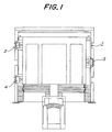
- a reference numeral 1 is a furnace, and three burners 2, 3 and 4 are attached to the furnace in the state that the burner 2 and 4 are opposed to the burner 3.
- the interior of the furnace body is divided into three upper, middle and lower stage control zones, and one burner is arranged in each control zone.
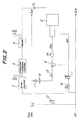
- Fig. 2 shows a burner combustion-controlling apparatus. Only a related portion of the burner 2 in the the upper stage control zone is shown.
- T2 is a temperature sensor
- reference numerals 5, 6 and 7 show an adjuster, an intermittent combustion controller, and a burner controller, respectively.
- the temperature sensor T2 detects the temperature in the upper stage control zone, and outputs a detected temperature,signal to the adjuster 5.
- the adjuster preliminarily stores a preset temperatures for the respective control zones, compares the detected temperature with the preset temperature based on the signal from the temperature sensor T2, and outputs a comparison result to the intermittent combustion controller 6.
- the intermittent combustion controller 6 preliminarily stores combustion cycling data including the combustion order, the combustion interval, the combustion duration, etc. for the burners, and receives the comparison results from the adjuster 5 and shortens the combustion duration for the burner in the control zone to be adjusted in temperature.
- the burner controller 7 outputs a control signal to a control valve 8.
- the control valve 8 is intermittently opened or closed upon receipt of a control signal outputted from the burner controller 7, so that air is fed to the upper stage burner 2 through the control valve 8. Interlockingly with this, a fuel gas is fed through a pressure-equalizing valve 9 to the burner 2 where combustion is effected. Signals are sent to the burner 3 in the control zone at the intermediate stage from the intermittent burner controller 6 as well as to the burner 4 in the control zone at the lower stage, so that similar control is effected.
- a reference numeral 10 is a pressure-equalizing valve which is always opened during operating the apparatus according to the present invention. This valve functions as an ordinary pressure-equalizing valve which regulates the flow rate of a fuel gas based on the pressure of air.
- Reference numerals 11 and 12 are a hand cock and a flow meter, respectively.
- Reference numerals 13 and 14 are a solenoid valve for safety purpose and a pressure-equalizing valve, respectively.
- the burner in each control zone is subjected to combustion according to the same pattern as shown in Fig. 6.
- the temperature sensor is fitted in each control zone, the time period during which the burner is subjected to combustion is adjusted based on a difference between the temperature detected by the temperature sensor and a preset temperature.
- Fig. 3 illustrates a concrete example of such controlling.
- the time period during which the burner 2 at the upper stage is subjected to combustion is gradually shortened, whereas if the detected temperature becomes lower than the lower limit of the preset temperature range, the shortened time period is restored to the original preset temperature.
- a similar controlling is illustrated with respect to the burner 3 at the intermediate state. Contrary to the conventional controlling process, according to the present invention, only the combustion time period is varied for each of the necessary combustions, but the intermittent combustion cycle is maintained as a whole as it is.
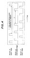
- the temperature sensor is fitted in each control zone.
- the burner in that control zone is skipped over through combustion preset for a given time period.
- Fig. 4 shows a concrete example of such controlling. For example, if the temperature in the control zone at the upper stage of the furnace exceeds the preset temperature and when time comes to subject the burner 2 at the upper stage to combustion, the burner is skipped over through combustion at this time. If the detected temperature becomes lower than the preset temperature, combustion of the burner 2 begins to be effected.
- Fig. 4 shows similar controlling with respect to the burner 3 at the intermediate stage. According to this control process, the burner or burners are skipped through combustion at given time period(s), but the intermittent combustion cycle is maintained as a whole as it is.
- a single burner is arranged in each of the control zones.
- the furnace body 1 is divided into three, i.e., upper, intermediate and lower control zones, and a plurality of burners 2, 3, 4 may be arranged in each control zone. In this case, those burners belonging to the same control zone are controlled together.
- a plurality of the control zones are arranged vertically in the above embodiments, such control zones may be defined in a lateral direction of the furnace body.
- a single temperature sensor may be arranged for every control zone or for every burner.
- the temperature in the furnace was set at 350°C, and a difference in the temperature distribution between an upper portion and a lower portion was measured.
- the temperature difference was 121°C in the case of the conventional combustion-controlling process as shown in Fig. 6, whereas the temperature difference was reduced to 83°C in the case of the combustion-controlling process according to the first aspect of the present invention.
- the variation in the temperature distribution inside the furnace can be diminished without damaging the advantage in the conventional intermittent burner combustion-controlling process. Accordingly, the invention process is favorably adopted to control the combustion of the burners in the furnace for firing the ceramic articles which are likely to be damaged by temperature differences.
Landscapes
- Engineering & Computer Science (AREA)
- Mechanical Engineering (AREA)
- General Engineering & Computer Science (AREA)
- Chemical & Material Sciences (AREA)
- Combustion & Propulsion (AREA)
- Physics & Mathematics (AREA)
- General Physics & Mathematics (AREA)
- Automation & Control Theory (AREA)
- Control Of Combustion (AREA)
- Regulation And Control Of Combustion (AREA)
Applications Claiming Priority (2)
| Application Number | Priority Date | Filing Date | Title |
|---|---|---|---|
| JP6057602A JP2677514B2 (ja) | 1994-03-28 | 1994-03-28 | バーナの燃焼制御方法 |
| JP57602/94 | 1994-03-28 |
Publications (2)
| Publication Number | Publication Date |
|---|---|
| EP0675325A1 true EP0675325A1 (fr) | 1995-10-04 |
| EP0675325B1 EP0675325B1 (fr) | 1999-06-02 |
Family
ID=13060411
Family Applications (1)
| Application Number | Title | Priority Date | Filing Date |
|---|---|---|---|
| EP95302046A Expired - Lifetime EP0675325B1 (fr) | 1994-03-28 | 1995-03-27 | Procédé et dispositif de commande de combustion des brûleurs dans un four |
Country Status (4)
| Country | Link |
|---|---|
| US (1) | US5630714A (fr) |
| EP (1) | EP0675325B1 (fr) |
| JP (1) | JP2677514B2 (fr) |
| DE (1) | DE69509964T2 (fr) |
Cited By (4)
| Publication number | Priority date | Publication date | Assignee | Title |
|---|---|---|---|---|
| BE1011655A3 (fr) * | 1997-03-28 | 1999-11-09 | Ngk Insulators Ltd | Procede de cuisson d'une piece brute ceramique. |
| NL1017448C2 (nl) * | 2001-02-26 | 2002-08-27 | Nederlandse Gasunie Nv | Ovenregeling voor warmtebehandeling van producten. |
| FR2853959A1 (fr) * | 2003-04-18 | 2004-10-22 | Stein Heurtey | Procede de controle de l'homogeneite de temperature des produits dans un four de rechauffage de siderurgie, et four de rechauffage |
| WO2016057892A1 (fr) * | 2014-10-10 | 2016-04-14 | Air Products And Chemicals, Inc. | Système de capteur intégré et procédés pour des processus de combustion |
Families Citing this family (4)
| Publication number | Priority date | Publication date | Assignee | Title |
|---|---|---|---|---|
| US6745708B2 (en) * | 2001-12-19 | 2004-06-08 | Conocophillips Company | Method and apparatus for improving the efficiency of a combustion device |
| JP4758716B2 (ja) * | 2005-09-16 | 2011-08-31 | 株式会社タムラ製作所 | 加熱装置の制御方法 |
| US7515986B2 (en) * | 2007-04-20 | 2009-04-07 | The Boeing Company | Methods and systems for controlling and adjusting heat distribution over a part bed |
| JP5742553B2 (ja) * | 2011-07-28 | 2015-07-01 | 株式会社ノーリツ | 燃焼装置 |
Citations (5)
| Publication number | Priority date | Publication date | Assignee | Title |
|---|---|---|---|---|
| GB1160926A (en) * | 1967-02-17 | 1969-08-06 | Astralux Dynamics Ltd | Method and apparatus for Controlling the Temperature of Furnaces or Kilns |
| US4480992A (en) * | 1981-10-17 | 1984-11-06 | Sanken Sangyo Kabushiki Kaisha | Method of heating a furnace |
| JPS62258930A (ja) * | 1986-05-06 | 1987-11-11 | Kurosaki Rokougiyou Kk | バツチ炉の燃焼制御方法 |
| EP0368033A1 (fr) * | 1988-10-17 | 1990-05-16 | Keller GmbH | Dispositif de réglage des brûleurs à gaz par impulsion d'un four tunnel |
| JPH06241439A (ja) * | 1993-02-22 | 1994-08-30 | Tokyo Gas Eng Kk | 複数バーナのon−off燃焼により制御する炉の加熱法 |
Family Cites Families (1)
| Publication number | Priority date | Publication date | Assignee | Title |
|---|---|---|---|---|
| JPH01150716A (ja) * | 1987-12-07 | 1989-06-13 | Nippon Steel Corp | サイド焚多帯式加熱炉の燃焼制御方法 |
-
1994
- 1994-03-28 JP JP6057602A patent/JP2677514B2/ja not_active Expired - Lifetime
-
1995
- 1995-03-27 DE DE69509964T patent/DE69509964T2/de not_active Expired - Fee Related
- 1995-03-27 EP EP95302046A patent/EP0675325B1/fr not_active Expired - Lifetime
- 1995-03-28 US US08/411,314 patent/US5630714A/en not_active Expired - Fee Related
Patent Citations (5)
| Publication number | Priority date | Publication date | Assignee | Title |
|---|---|---|---|---|
| GB1160926A (en) * | 1967-02-17 | 1969-08-06 | Astralux Dynamics Ltd | Method and apparatus for Controlling the Temperature of Furnaces or Kilns |
| US4480992A (en) * | 1981-10-17 | 1984-11-06 | Sanken Sangyo Kabushiki Kaisha | Method of heating a furnace |
| JPS62258930A (ja) * | 1986-05-06 | 1987-11-11 | Kurosaki Rokougiyou Kk | バツチ炉の燃焼制御方法 |
| EP0368033A1 (fr) * | 1988-10-17 | 1990-05-16 | Keller GmbH | Dispositif de réglage des brûleurs à gaz par impulsion d'un four tunnel |
| JPH06241439A (ja) * | 1993-02-22 | 1994-08-30 | Tokyo Gas Eng Kk | 複数バーナのon−off燃焼により制御する炉の加熱法 |
Non-Patent Citations (2)
| Title |
|---|
| PATENT ABSTRACTS OF JAPAN vol. 012, no. 137 (M - 690) 26 April 1988 (1988-04-26) * |
| PATENT ABSTRACTS OF JAPAN vol. 018, no. 628 (M - 1713) 30 November 1994 (1994-11-30) * |
Cited By (8)
| Publication number | Priority date | Publication date | Assignee | Title |
|---|---|---|---|---|
| BE1011655A3 (fr) * | 1997-03-28 | 1999-11-09 | Ngk Insulators Ltd | Procede de cuisson d'une piece brute ceramique. |
| NL1017448C2 (nl) * | 2001-02-26 | 2002-08-27 | Nederlandse Gasunie Nv | Ovenregeling voor warmtebehandeling van producten. |
| EP1235045A1 (fr) * | 2001-02-26 | 2002-08-28 | Energie Techniek B.V. | Contrôle d'un four pour le traitement thermique de produits |
| FR2853959A1 (fr) * | 2003-04-18 | 2004-10-22 | Stein Heurtey | Procede de controle de l'homogeneite de temperature des produits dans un four de rechauffage de siderurgie, et four de rechauffage |
| WO2004094931A3 (fr) * | 2003-04-18 | 2005-05-06 | Stein Heurtey | Procede de controle de l'homogeneite de temperature des produits dans un four de rechauffage de siderurgie, et four de rechauffage. |
| US7540992B2 (en) | 2003-04-18 | 2009-06-02 | Fives Stein | Method for controlling the homogeneity of the temperature of products in a metallurgical reheating furnace, and reheating furnace |
| WO2016057892A1 (fr) * | 2014-10-10 | 2016-04-14 | Air Products And Chemicals, Inc. | Système de capteur intégré et procédés pour des processus de combustion |
| US10161682B2 (en) | 2014-10-10 | 2018-12-25 | Air Products And Chemicals, Inc. | Integrated sensor system and methods for combustion processes |
Also Published As
| Publication number | Publication date |
|---|---|
| US5630714A (en) | 1997-05-20 |
| EP0675325B1 (fr) | 1999-06-02 |
| DE69509964D1 (de) | 1999-07-08 |
| JP2677514B2 (ja) | 1997-11-17 |
| JPH07269852A (ja) | 1995-10-20 |
| DE69509964T2 (de) | 1999-10-21 |
Similar Documents
| Publication | Publication Date | Title |
|---|---|---|
| US4850310A (en) | Boiler control having reduced number of boiler sequences for a given load | |
| US5090200A (en) | Regeneration system for particulate trap | |
| US5630714A (en) | Process for controlling combustion of burners in furnace and an apparatus therefor | |
| US4485786A (en) | Air-fuel ratio control apparatus | |
| US4698574A (en) | Process control apparatus | |
| KR100342657B1 (ko) | 공업용 로의 온도 추정제어 방법 및 그 장치 | |
| US4442817A (en) | Electronically controlled fuel metering system | |
| KR101112072B1 (ko) | 연속식 가열로의 로압 제어 방법 및 그 장치 | |
| RU2068006C1 (ru) | Способ управления нагревом металла в пламенной нагревательной печи | |
| JPH0875151A (ja) | 熱処理炉 | |
| KR100345713B1 (ko) | 고로 열풍로 냉풍유량 제어방법 | |
| JPS6117359Y2 (fr) | ||
| EP0757307A2 (fr) | Dispositif pour réguler la température dans un four | |
| JP2759342B2 (ja) | コークス炉焼成時間のばらつき低減方法 | |
| SU1121545A1 (ru) | Способ управлени подачей топлива в нагревательную печь | |
| JPS63182066A (ja) | 乾燥炉の昇温制御装置 | |
| JPS63238191A (ja) | コ−クス炉の炉長温度分布制御法 | |
| JPH0227325Y2 (fr) | ||
| JP2899236B2 (ja) | パルス燃焼装置 | |
| JP3190552B2 (ja) | 加熱炉燃焼設備の起動方法及び装置 | |
| JPS61133328A (ja) | ドワイトロイド式焼結機の点火炉燃料調整方法 | |
| JPH08178551A (ja) | 燃焼制御系の温度制御方法 | |
| JPH0367952A (ja) | 給湯装置 | |
| JPH0580864A (ja) | 炉温燃焼制御方法 | |
| JPH0726135B2 (ja) | 熱風炉の温度制御装置 |
Legal Events
| Date | Code | Title | Description |
|---|---|---|---|
| PUAI | Public reference made under article 153(3) epc to a published international application that has entered the european phase |
Free format text: ORIGINAL CODE: 0009012 |
|
| AK | Designated contracting states |
Kind code of ref document: A1 Designated state(s): DE FR GB |
|
| 17P | Request for examination filed |
Effective date: 19951205 |
|
| 17Q | First examination report despatched |
Effective date: 19970129 |
|
| GRAG | Despatch of communication of intention to grant |
Free format text: ORIGINAL CODE: EPIDOS AGRA |
|
| GRAG | Despatch of communication of intention to grant |
Free format text: ORIGINAL CODE: EPIDOS AGRA |
|
| GRAH | Despatch of communication of intention to grant a patent |
Free format text: ORIGINAL CODE: EPIDOS IGRA |
|
| GRAH | Despatch of communication of intention to grant a patent |
Free format text: ORIGINAL CODE: EPIDOS IGRA |
|
| GRAA | (expected) grant |
Free format text: ORIGINAL CODE: 0009210 |
|
| AK | Designated contracting states |
Kind code of ref document: B1 Designated state(s): DE FR GB |
|
| REF | Corresponds to: |
Ref document number: 69509964 Country of ref document: DE Date of ref document: 19990708 |
|
| ET | Fr: translation filed | ||
| PGFP | Annual fee paid to national office [announced via postgrant information from national office to epo] |
Ref country code: GB Payment date: 20000317 Year of fee payment: 6 |
|
| PGFP | Annual fee paid to national office [announced via postgrant information from national office to epo] |
Ref country code: FR Payment date: 20000320 Year of fee payment: 6 |
|
| PGFP | Annual fee paid to national office [announced via postgrant information from national office to epo] |
Ref country code: DE Payment date: 20000322 Year of fee payment: 6 |
|
| PLBE | No opposition filed within time limit |
Free format text: ORIGINAL CODE: 0009261 |
|
| STAA | Information on the status of an ep patent application or granted ep patent |
Free format text: STATUS: NO OPPOSITION FILED WITHIN TIME LIMIT |
|
| 26N | No opposition filed | ||
| PG25 | Lapsed in a contracting state [announced via postgrant information from national office to epo] |
Ref country code: GB Free format text: LAPSE BECAUSE OF NON-PAYMENT OF DUE FEES Effective date: 20010327 |
|
| GBPC | Gb: european patent ceased through non-payment of renewal fee |
Effective date: 20010327 |
|
| PG25 | Lapsed in a contracting state [announced via postgrant information from national office to epo] |
Ref country code: FR Free format text: LAPSE BECAUSE OF NON-PAYMENT OF DUE FEES Effective date: 20011130 |
|
| REG | Reference to a national code |
Ref country code: FR Ref legal event code: ST |
|
| PG25 | Lapsed in a contracting state [announced via postgrant information from national office to epo] |
Ref country code: DE Free format text: LAPSE BECAUSE OF NON-PAYMENT OF DUE FEES Effective date: 20020101 |