EP0675343B1 - Dispositif de détection d'un point fixe - Google Patents
Dispositif de détection d'un point fixe Download PDFInfo
- Publication number
- EP0675343B1 EP0675343B1 EP95104723A EP95104723A EP0675343B1 EP 0675343 B1 EP0675343 B1 EP 0675343B1 EP 95104723 A EP95104723 A EP 95104723A EP 95104723 A EP95104723 A EP 95104723A EP 0675343 B1 EP0675343 B1 EP 0675343B1
- Authority
- EP
- European Patent Office
- Prior art keywords
- light
- hologram
- holograms
- light source
- center plane
- Prior art date
- Legal status (The legal status is an assumption and is not a legal conclusion. Google has not performed a legal analysis and makes no representation as to the accuracy of the status listed.)
- Expired - Lifetime
Links
- 239000000758 substrate Substances 0.000 claims description 62
- 238000005259 measurement Methods 0.000 claims description 18
- 239000013598 vector Substances 0.000 claims description 14
- 239000011295 pitch Substances 0.000 description 10
- 238000001514 detection method Methods 0.000 description 8
- 238000000034 method Methods 0.000 description 7
- 230000003287 optical effect Effects 0.000 description 5
- 239000003504 photosensitizing agent Substances 0.000 description 5
- 239000000853 adhesive Substances 0.000 description 4
- 230000005540 biological transmission Effects 0.000 description 4
- 239000006059 cover glass Substances 0.000 description 2
- 230000003247 decreasing effect Effects 0.000 description 2
- 238000006073 displacement reaction Methods 0.000 description 2
- 238000004519 manufacturing process Methods 0.000 description 2
- 230000004304 visual acuity Effects 0.000 description 2
- 230000001419 dependent effect Effects 0.000 description 1
- 230000023077 detection of light stimulus Effects 0.000 description 1
- 238000010586 diagram Methods 0.000 description 1
- 239000011521 glass Substances 0.000 description 1
- 230000001678 irradiating effect Effects 0.000 description 1
- 238000003754 machining Methods 0.000 description 1
- 229920006395 saturated elastomer Polymers 0.000 description 1
Images




Classifications
-
- G—PHYSICS
- G01—MEASURING; TESTING
- G01D—MEASURING NOT SPECIALLY ADAPTED FOR A SPECIFIC VARIABLE; ARRANGEMENTS FOR MEASURING TWO OR MORE VARIABLES NOT COVERED IN A SINGLE OTHER SUBCLASS; TARIFF METERING APPARATUS; MEASURING OR TESTING NOT OTHERWISE PROVIDED FOR
- G01D5/00—Mechanical means for transferring the output of a sensing member; Means for converting the output of a sensing member to another variable where the form or nature of the sensing member does not constrain the means for converting; Transducers not specially adapted for a specific variable
- G01D5/26—Mechanical means for transferring the output of a sensing member; Means for converting the output of a sensing member to another variable where the form or nature of the sensing member does not constrain the means for converting; Transducers not specially adapted for a specific variable characterised by optical transfer means, i.e. using infrared, visible, or ultraviolet light
- G01D5/32—Mechanical means for transferring the output of a sensing member; Means for converting the output of a sensing member to another variable where the form or nature of the sensing member does not constrain the means for converting; Transducers not specially adapted for a specific variable characterised by optical transfer means, i.e. using infrared, visible, or ultraviolet light with attenuation or whole or partial obturation of beams of light
- G01D5/34—Mechanical means for transferring the output of a sensing member; Means for converting the output of a sensing member to another variable where the form or nature of the sensing member does not constrain the means for converting; Transducers not specially adapted for a specific variable characterised by optical transfer means, i.e. using infrared, visible, or ultraviolet light with attenuation or whole or partial obturation of beams of light the beams of light being detected by photocells
- G01D5/36—Forming the light into pulses
- G01D5/38—Forming the light into pulses by diffraction gratings
Definitions
- the present invention relates to a fixed point detecting device according to the preamble of claim 1, and more particularly, to a fixed point detecting device using detection of lights diffracted by holographic diffraction gratings, which is suitable for detection of a dislocation of a substrate upon multiplex exposure of an integrated circuit, and detection of the origin of an encoder, etc.
- a fixed point detecting device is known from JP-A 4-324316.
- the reference point or the origin is established to measure an exact position or distance.
- the fixed point detecting device is used for establishing such reference point or origin.
- JP-A 61-153501 One of known fixed point detecting devices is disclosed in JP-A 61-153501. This device is constructed to detect a fixed point through a mark, and includes a laser generator, a position sensor, etc. A laser beam out of the laser generator is diffracted by diffraction gratings of the mark, and first-order diffracted lights are detected by the position sensor. The position sensor serves to determine an angle of diffraction at which the intensity of diffracted lights is maximum. A value of the angle of diffraction at which the intensity of diffracted lights is maximum is varied when a laser beam spot passes across a boundary of two portions of the mark, i.e. before and behind the boundary of the two portions of the mark. The fixed point is detected by such variation in the angle of diffraction.
- Another of the known fixed point detecting devices is a variant of the above device.
- This variant uses two transmission and volume-type holographic diffraction gratings or holograms and two photo detectors.
- the transmission and volume-type holographic diffraction gratings diffracted lights are gone out on the side opposite to incident lights with respect to the holographic diffraction gratings. Therefore, the photo detectors are disposed on the side opposite to the laser generator with respect to the holographic diffraction gratings.
- the holographic diffraction gratings have grating intervals or grating pitches different from each other.
- Zero-order diffracted lights, positive first-order diffracted lights, negative first-order diffracted lights, and high-order diffracted lights are obtained by the diffraction gratings.
- the photo detectors detect positive first-order diffracted lights.
- JP-A 4-324316 The other of the known fixed point detecting devices is disclosed in JP-A 4-324316.
- This device includes a stationary portion and a movable portion which is movable in the direction of measurement, the stationary portion having an optical system and a detecting system, and the movable portion having a substrate and two volume-type holographic diffraction gratings or holograms disposed thereon.
- the two holograms are disposed on the substrate on an upper side thereof to be adjacent to each other.
- the two holograms are constructed symmetrically with respect to a center plane.
- angles of inclination of distributed planes of the holograms are symmetrically and continuously varied on both sides of the center plane, and grating intervals or grating-pitch thereof are symmetrically and continuously varied on both sides of the center plane.
- the two holograms are disposed so that points at which the diffraction efficiencies become maximum are different from each other in the direction of measurement.
- the movable portion When the movable portion is moved relative to the stationary portion, i.e. with respect to light receivers and a light source which are stationary, light diffracted by the first hologram is detected by the first light receiver, whereas light diffracted by the second hologram is detected by the second light receiver.
- the points at which the diffraction efficiencies become maximum are different from each other, so that a peak position of a luminous intensity curve of diffracted light detected by the first light receiver is different from a peak position of a luminous intensity curve of diffracted light detected by the second light receiver. That is, there exists a point at which the two luminous intensities are equal to each other. Such point is a fixed point obtained by this fixed point detecting device.
- the position sensor serves as a light receiving device.
- the position sensor is constructed to detect an angle of diffraction at which the intensity of diffracted lights is maximum, resulting in low resolving power.
- a position sensor is expensive which allows accurate detection of the angle of diffraction.
- the two holographic diffraction gratings have grating intervals or grating pitches different from each other, and the positive first-order diffracted lights and the negative first-order diffracted lights are gone out on both sides with respect to the direction of incident lights. Therefore, in order to detect the two positive first-order diffracted lights, the two photo detectors should be disposed adjacently. Moreover, the two positive first-order diffracted lights should be separated completely for detection through the photo detectors. This can be obtained by simply enlarging a difference between the grating interval of the first hologram and the grating interval of the second hologram. However, when enlarging a difference between the grating intervals of the two holograms, an error is increased with a variation in a wavelength of lights out of the light source.
- the two holograms are constructed symmetrically with respect to the center plane, the fixed point is not changed even with a variation in the wavelength of lights out of the light source.
- the two light receivers should be disposed accurately with respect to the two holograms. If not, the resolving power is lowered.
- an object of the present invention to provide a fixed point detecting device which enables accurate determination of a fixed point.
- a system for detecting a fixed point comprising: the features of claim 1.
- Another aspect of the present invention lies in providing a system for detecting a fixed point, the system having an axis of measurement, comprising: the features of claim 14.
- a hologram comprising:
- An example which is useful for understanding the present invention describes a method of forming a hologram having two portions separated by an imaginary center plane perpendicular thereto, comprising the steps of:
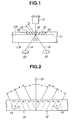
- a fixed point detecting device includes a transparent substrate 31 and two holographic diffraction gratings 32, 33 formed on an upper side 31A thereof. Disposed above the substrate 31 is a light source 12, and disposed therebelow is a pair of light receivers 22, 23 for receiving diffracted lights.
- the substrate 31 and the holographic diffraction gratings 32, 33 constitute a movable portion, whereas the light source 12 and the light receivers 22, 23 constitute a stationary portion. It is noted that a condenser lens and an electric processing circuit are not shown.
- the holographic diffraction gratings 32, 33 are formed by volume-type holograms. As for such holograms, a refractive index is changed from “n 1 " to "n 2 " at a predetermined pitch "d". Diffraction gratings are formed with such a change in the refractive index.
- thick lines 42, 43 indicate distributed planes of the refractive index of the volume-type holograms. An interval of each plane 42, 43 is referred to as a grating interval or grating pitch "d".
- Grating vectors V are perpendicular to the distributed planes 42, 43.
- the holographic diffraction gratings are referred to as holograms whenever need arises.
- a center plane 35 which is perpendicular to upper sides of the holograms 32, 33.
- the angle of inclination of the distributed planes 42, 43 with respect to the center plane 35 is ⁇ .
- the angles of inclination of the grating vectors V with respect to the distributed planes 42, 43 are 90° - ⁇ .
- the two holograms 32, 33 are constructed symmetrically with respect to the center plane 35.
- the two holograms 32, 33 have the grating vectors V symmetrically inclined at the same angle of inclination with respect to the center plane 35.
- the two holograms 32, 33 have the same grating interval or grating-pitch "d".
- Diffracted lights obtained by the two holograms 32, 33 have the following features:
- the grating interval or pitch "d" of the holographic diffraction gratings 32, 33 is between 0.1 and 100 ⁇ m.
- the accuracy in the order of 0.01 ⁇ m is possible in connection with detection of the fixed point.
- This detection accuracy can further be increased by further decreasing the diameter D of the beam spot.
- the holographic diffraction gratings 32, 33 are transmission and volume-type holograms. Therefore, the positive first-order diffracted lights 1A, 1B are gone out on the side opposite to incident lights through the transparent substrate 31.
- the light receivers 22, 23 are disposed on the side opposite to the light source 12 with respect to the holograms 32, 33.
- Figs. 13A and 13B the luminous intensity curves as shown in Fig. 13A and the luminous intensity difference curve as shown in Fig. 13B are obtained. It is noted that Fig. 1 shows a state that lights are fell on just a portion of the center plane 35.
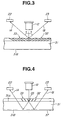
- Fig. 3 shows a second embodiment of the present invention.
- the second embodiment is a variant of the first embodiment as shown in Fig. 1.
- the holographic diffraction gratings 32, 33 are reflection and volume-type holograms. Therefore, the positive first-order diffracted lights 1A, 1B are gone out on the same side as incident lights.
- the light receivers 22, 23 are disposed on the same side as the light source 12 with respect to the holograms 32, 33.
- Fig. 4 shows a third embodiment of the present invention.
- the third embodiment is a variant of the first embodiment as shown in Fig. 1.
- the holographic diffraction gratings 32, 33 are transmission and volume-type holograms.
- a reflecting film 37 is arranged on a lower side 31B of the transparent substrate 31.
- the light receivers 22, 23 are disposed on the same side as the light source 12 with respect to the substrate 31. Lights out of the light source 12 are diffracted by the holograms 32, 33, and the positive first-order diffracted lights 1A, 1B which reach the reflecting film 37 through the transparent substrate 31 are reflected by the reflecting film 37, and received by the light receivers 22, 23 after passing through the substrate 31 again.
- the transmission-type holograms 32, 33 are used, the light receivers 22, 23 can be disposed on the same side as the light source 12, enabling a reduction in size of the device.
- Fig. 5 shows a fourth embodiment of the present invention.
- the fourth embodiment is a variant of the third embodiment as shown in Fig. 4.
- a reflecting plate 39 is disposed below the substrate 31.
- the light receivers 22, 23 are disposed on the same side as the light source 12 with respect to the substrate 31.
- Lights out of the light source 12 are diffracted by the holograms 32, 33, and the positive first-order diffracted lights 1A, 1B which reach the reflecting plate 39 through the transparent substrate 31 are reflected by the reflecting plate 39, and received by the light receivers 22, 23 after passing through the substrate 31 again.
- Fig. 6 shows a fifth embodiment of the present invention.
- the fifth embodiment is a variant of the first embodiment as shown in Fig. 1.
- a third receiver 24 is arranged to detect zero-order diffracted lights 0.
- the three light receivers 22, 23, 24 are disposed on the side opposite to the light source 12 with respect to the substrate 31. Lights out of the light source 12 are diffracted by the holograms 32, 33, and the positive first-order diffracted lights 1A, 1B are detected by the two light receivers 22, 23, whereas the zero-order diffracted lights 0 are detected by the third light receiver 24.
- the luminous intensity difference curve is obtained out of the two luminous intensity curves of the positive first-order diffracted lights 1A, 1B detected by the first and second light receivers 22, 23.
- a gate signal is obtained by the zero-order diffracted lights 0 detected by the third light receiver 24.
- the gate signal corresponds to a curve G1 indicated by a dotted line in Fig. 13B.
- the gate signal G1 can be used for confirming a presence of the fixed point.
- a curve C3 indicated by a fully-drawn line in Fig. 13B it is necessary to judge whether the curve C3 is obtained by the first and second light receivers 22, 23 or due to the other factor such as noise. If the gate signal G1 is obtained simultaneously with the curve C3, it is confirmed that the curve C3 is a luminous intensity difference curve.
- lights out of the light source 12 are diffracted only once by the holograms 32, 33 before being detected by the light receivers 22, 23, 24.
- lights out of the light source 12 are diffracted twice. That is, lights diffracted by the holograms 22, 23 are reflected by the opposite side of the substrate 31, and diffracted by the holograms 32, 33 again.
- Fig. 7 shows a sixth embodiment of the present invention.
- the sixth embodiment is a variant of the third embodiment as shown in Fig. 4.
- the holograms 32, 33 are formed in a larger zone than in the third embodiment as shown in Fig. 4.
- a dimension of the zone having the holograms 32, 33 formed therein should sufficiently be large so that diffracted lights reflected by the reflecting film 37 on the opposite side of the substrate 31 can be diffracted by the holograms 32, 33 again. That is, a dimension of the zone of the holograms 32, 33 should have a sufficient magnitude so that two diffractions are possible when the illuminated point or zone, i.e. beam spot, traverses the center plane 35 so as to obtain the luminous intensity curves in Fig. 13A and the luminous intensity difference curve in Fig. 13B.
- the second diffraction is carried out by the other hologram than that of the first diffraction.
- the light 1A diffracted by the first hologram 32 is reflected by the reflecting film 37, then diffracted by the second hologram 33.
- a diffracted light 1A' obtained by the second hologram 33 is detected by the first light receiver 22.
- the light 1B diffracted by the second hologram 33 is reflected by the reflecting film 37, then diffracted by the first hologram 32.
- a diffracted light 1B' obtained by the first hologram 32 is detected by the second light receiver 23.
- the outgoing lights 1A', 1B' are parallel to incident lights. That is, if incident lights are perpendicular to the upper sides of the holograms 32, 33, i.e. in parallel to the center plane 35, the diffracted lights 1A', 1B' obtained by the second diffraction are perpendicular to the upper sides of the holograms 32, 33, i.e. in parallel to the center plane 35.
- the second diffraction is carried out by the other hologram than that of the first diffraction.
- the diffraction efficiencies of the first and second holograms 32, 33 are ⁇ 1 , ⁇ 2 , respectively.
- the total efficiency is ⁇ 1 x ⁇ 2 .
- the total efficiency is ⁇ 2 x ⁇ 1 .
- Fig. 8 shows a seventh embodiment of the present invention.
- the seventh embodiment is a variant of the sixth embodiment as shown in Fig. 7.
- third and fourth light receivers 24, 25 are arranged to detect the zero-order diffracted lights.
- the light receivers 22, 23, 24, 25 are disposed on the same side as the light source 12 with respect to the substrate 31. Lights out of the light source 12 are diffracted by the holograms 32, 33, and the positive first-order diffracted lights 1A', 1B' are detected by the first and second light receivers 22, 23, whereas the zero-order diffracted lights 0A, 0B are detected by the third and fourth light receivers 24, 25.
- a first luminous intensity curve is obtained by adding the positive first-order diffracted light 1A' detected by the first light receiver 22 and the zero-order diffracted light 0A detected by the third light receiver 24, whereas a second luminous intensity curve is obtained by adding the positive first-order diffracted light 1B' detected by the second light receiver 23 and the zero-order diffracted light 0B detected by the fourth light receiver 25.
- One luminous intensity difference curve is obtained by the two luminous intensity curves.
- Fig. 9 shows an eighth embodiment of the present invention.
- the eighth embodiment is a variant of the sixth embodiment as shown in Fig. 7.
- the reflecting film is not arranged on the lower side 31B of the substrate 31.
- an angle of incidence ⁇ of diffracted lights is appropriately established with respect to the lower side 31 B of the substrate 31 so that diffracted lights are totally reflected by the lower side 31B of the substrate 31.
- a critical angle ⁇ C of lights fell on the lower side 31B of the substrate 31 through the holograms 32, 33 is equal to n 0 /n B .
- the substrate 31 is made of glass having a refractive index n B of 1.5, and a refractive index of air n 0 , is equal to 1, the critical angle ⁇ C is equal to 41.8 degrees.
- Fig. 10 shows a ninth embodiment of the present invention.
- the ninth embodiment is a variant of the eighth embodiment as shown in Fig. 9.
- positions of the light receivers 22, 23 with respect to the light source 12 are dependent on the thickness "t s " of the substrate 31. If the thickness "t s " of the substrate 31 is greater, positions of the outgoing lights 1A', 1B' are distant from the light source 12, so that the light receivers 22, 23 should be disposed distant from the light source 12. Contrarily, if the thickness "t s " of the substrate 31 is smaller, the positions of the outgoing lights 1A', 1B' are close to the light source 12, so that the light receivers 22, 23 should be disposed close to the light source 12.
- each of the two holograms 32, 33 comprises two portions. That is, the first hologram 32 includes an inner portion 32A adjacent to the center plane 35 and an outer portion 32B distant from the center plane 35, the two portions having grating vectors and grating pitches "d" different from each other. Likewise, the second hologram 33 includes an inner portion 33A adjacent to the center plane 35 and an outer portion 33B distant from the center plane 35, the two portion having grating vectors and grating pitches "d" different from each other.
- the outgoing lights 1A', 1B' are inclined with respect to incident lights so that the light receivers 22, 23 can be disposed distant from or close to the light source 12.
- Fig. 10 shows a case that the outgoing lights 1A', 1B' are inclined to be close to incident lights so as to dispose the light receivers 22, 23 close to the light source 12.
- the outer portions 32B, 33B of the holograms 32, 33 may be constructed so that the outgoing lights 1A', 1B' are inclined outward with respect to incident lights.
- the light receivers 22, 23 can be disposed more distant from the light source 12.
- Fig. 11 shows a tenth embodiment of the present invention.
- the tenth embodiment is a variant of the eight embodiment as shown in Fig. 9.
- the grating vectors of the holograms 32, 33 are inclined in the direction opposite to the inclination of the grating vectors in the eighth embodiment as shown in Fig. 9.
- the reflecting film is not arranged on the lower side 31B of the substrate 31, diffracted lights are totally reflected by the lower side 31B of the substrate 31.
- the two light receivers 22, 23 are disposed on the side opposite to the light source 12.
- the second diffraction is carried out by the same holograms as those of the first diffraction.
- the light 1A diffracted by the first hologram 32 is totally reflected by the lower side 31B of the substrate 31, then diffracted by the first hologram 32.
- the diffracted light 1A' obtained by the first hologram 32 is detected by the first light receiver 22.
- the light 1B diffracted by the second hologram 33 is totally reflected by the lower side 31B of the substrate 31, then diffracted by the second hologram 33.
- the diffracted light 1B' obtained by the second hologram 33 is detected by the second light receiver 23.
- the holograms 32, 33 perpendicularly with respect to the upper sides thereof, i.e. in parallel to the center plane 35, diffracted lights received by the light receivers 22, 23 are parallel to incident lights to the holograms 32, 33.
- lights out of the light source 12 are fell on the holograms 32, 33 perpendicularly with respect to the upper sides thereof, i.e. in parallel to the center plane 35, and the diffracted lights 1A', 1B' obtained by the second diffraction are gone out from the holograms 32, 33 perpendicularly with respect to the lower sides thereof, i.e. in parallel to the center plane 35.
- Fig. 12 is a general view of the eighth embodiment as shown in Fig. 9.
- a cover glass 51 is disposed on the upper sides of the holograms 32, 33 through an adhesive agent layer 49.
- the electric processing circuit 29 may be constructed in a way similar to the known electric processing circuit. It is noted that in Fig. 12, reference numerals 14A to 14C designate a condenser lens.
- Fig. 13A shows two luminous intensity curves C1, C2 obtained by the two light receivers 22, 23, and Fig. 13B shows a luminous intensity difference curve C3 obtained by the differential amplifier 29-2.
- the two luminous intensity curves C1, C2 are constant after luminous intensity signals increase. This reveals that the diffraction efficiency is improved by the fixed point detecting device of the present invention.
- the intensities of the positive first-order diffracted lights 1A, 1B detected by the light receivers 22, 23 are extremely great, detecting portions of the light receivers 22, 23 are saturated. Flat portions of the two luminous intensity curves C1, C2 indicate such saturation. Therefore, the luminous intensity difference curve C3 is constant before and behind the zero cross point as shown in Fig. 13B.
- FIG. 14 a description will be made with regard to an example of a method of forming the volume-type holograms 32, 33 on the upper side 31A of the substrate 31.
- a photosensitizer 53 is placed on the upper side 31A of the substrate 31, and a masque 55 is perpendicularly disposed thereabove. From both sides of the masque 55, plane waves 61, 62, 63, 64 are simultaneously fell on the upper side 31A of the substrate 31 at angles of incidence ⁇ ⁇ A , ⁇ ⁇ B , exposing the photosensitizer 53.
- the plane waves 61, 62 having the angles of incidence + ⁇ A , + ⁇ B serve to form the first hologram 32 on the right side of the center plane 35
- the plane waves 63, 64 having the angles of incidence - ⁇ A , - ⁇ B serve to form the second hologram 33 on the left side of the center plane 35.
- the two symmetrical holograms 32, 33 are simultaneously formed on both sides of the center plane 35.
- the masque 55 has a slender wedge-shaped section, and a sharp-pointed end portion.
- the masque 5 is disposed so that the end portion is in contact with the upper side 31A of the substrate 31. It is preferable to avoid as much as possible a production of a shadow of the masque 55 on the center plane 35, and to prevent a needless image of grating from being produced due to diffraction by the end portion of the masque 55.
- Fig. 15 shows another example of a method of forming the holograms 32, 33.
- the volume-type hologram 32 is formed on an upper side 31A of a first substrate 31, whereas the volume-type hologram 33 is formed on an upper side 51A of a second substrate 51.
- Such holograms 32, 33 are formed by the known method, each having a grating vector V inclined at a predetermined angle of inclination.
- one of the holograms 32, 33 is turned over, and put on the other.
- An adhesive agent 41 is placed therebetween.
- the first hologram 32 on the right side and the second hologram 33 on the left side are disposed to have the grating vectors V symmetrically inclined with respect to the center plane 35.
- the first hologram 32 and the second hologram 33 are dislocated with each other in the vertical direction by the thickness of the adhesive agent 41. Therefore, if the thickness of the adhesive agent 41 is fully decreased, the same structure as that of the eighth embodiment in Fig. 9 is obtained. It is noted that the two transparent substrates 31, 51 serve as a cover glass, respectively.
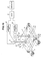
- Fig. 16 is a general view of an eleventh embodiment of the present invention.
- the fixed point detecting device is constructed to include two fixed point detecting portions.
- the fixed point detecting device of the type may be used, for example, in an X-ray exposure drawing device.
- the X-ray exposure drawing device includes two rails 71, 71 and a stage 73 which is movable thereon in the direction of measurement or X-direction.
- An object to be detected 75 for example, a photosensitizer, is placed on an upper side 73A of the stage 73, and the object 75 has a fixed point P to be detected.
- the fixed point P should accurately be detected by the fixed point detecting device.
- detection of the fixed point P is carried out by a single fixed point detecting device. Therefore, when the stage 73 is yawed as indicated by arrows "y" in Fig. 16 with respect to the direction of measurement or X-direction, the fixed point cannot be detected accurately.
- holograms 77A, 77B are placed on the upper side 73A of the stage 73 and on both sides of the object 75.
- Each hologram 77A, 77B includes two holograms 32, 33 as described above.
- the two holograms 32, 33 are disposed in the direction of measurement or X-direction, and constructed to be symmetrical with respect to the center plane.
- Two fixed point detecting portions are disposed corresponding to the holograms 77A, 77B, each portion having an optical system and a detecting system.
- the optical system includes the light source 12, and the detecting system includes a pair of light receivers 22, 23 and the electric processing circuit 80.
- the fixed point detecting device includes an adder 81 for adding output signals of the differential amplifiers 80-2, and a comparator 83 which inputs output of the adder 81.
- Figs. 18A to 18C show output signals of the two differential amplifiers 80-2 and the adder 81.
- a curve C3-1 of a fully-drawn line in Fig. 18A indicates an output signal of the first differential amplifier 80-2
- a curve C3-2 of a fully-drawn line in Fig. 18B indicates an output signal of the second differential amplifier 80-2
- a curve C4 of a fully-drawn line in Fig. 18C indicates an output signal of the adder 81.
- the X-axis is taken via the fixed point P of the object to be detected 75 and in the direction of measurement.
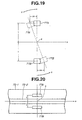
- the holograms 77A, 77B placed on the upper side 73A of the stage 73 of the X-ray exposure drawing device are symmetrically disposed with respect to the X-axis, and that a distance from the X-axis to each hologram 77A, 77B is "t".
- the fixed point detecting devices are disposed corresponding to the holograms 77A, 77B on both sides of the object 75.
- the holograms 77A, 77B placed on the upper side 73A of the stage 73 are also yawed as indicated by arrows "y" in Fig. 19.
- the holograms 77A, 77B produce rotary motion around the fixed point P.
- the two holograms 77A, 77B are moved by the same distance in the opposite direction.
- the first hologram 77A is moved by ⁇ X in the negative direction of the X-axis
- the second hologram 77B is moved by ⁇ X in the positive direction of the X-axis.
- curves of a broken line indicate output signals of the two differential amplifiers 80-2 and the adder 81 when the stage 73 is yawed.
- the curve C3-1' of a broken line in Fig. 18A indicates an output signal of the first differential amplifier 80-2
- the curve C3-2' of a broken line in Fig. 18B indicates an output signal of the second differential amplifier 80-2
- the curve C4' of a broken line in Fig. 18C indicates an output signal of the adder 81.
- the output signal of the adder 81 is provided to the camparator 83, obtaining the zero cross point. As indicated by the curve C4'of a broken line in Fig. 18C, the output signal of the adder 81 is varied with yawing, while the zero cross point is not changed. In the eleventh embodiment, the output signals of the two differential amplifiers 80-2 are varied with yawing, which are added, however, by the adder 81, having a variation part canceled.
- Fig. 20 shows an example wherein the fixed point detecting device of the present invention is used in a linear encoder.
- the linear encoder has a scale substrate 75-1 having an upper side on which a diffraction grating 75-2 for detecting a displacement is disposed along the axis of measurement or X-axis. A displacement in the axis of measurement (X-axis) is detected by the diffraction grating 75-2.
- the holograms 77A, 77B are symmetrically placed on both sides of the diffraction grating 75-2 for detecting a fixed point.
- the fixed point detecting device includes two fixed point detecting portions corresponding to the two holograms 77A, 77B, each portion having an optical system and a detecting system. It is noted that such optical system and detecting system of the fixed point detecting portion may be the same as those in the eleventh embodiment of the present invention as shown in Fig. 16. In such a way, in this example also, an error due to yawing of the scale substrate 75-1 can be eliminated in the same way as in the eleventh embodiment.
Landscapes
- Physics & Mathematics (AREA)
- General Physics & Mathematics (AREA)
- Length Measuring Devices By Optical Means (AREA)
- Optical Transform (AREA)
Claims (15)
- Système pour détecter un point fixe, le système possédant un axe de mesure comprenant :une source de lumière (12) pour fournir de la lumière ;un moyen pour diffracter la lumière fournie par ladite source de lumière (12), ledit moyen de diffraction comportant deux portions (32, 33) adjacentes .l'une à l'autre et séparées par un plan central imaginaire (35) perpendiculaire à celles-ci, les deux portions précitées (32, 33) étant agencées d'une manière symétrique des deux côtés dudit plan central imaginaire (35) ;un moyen pour détecter les intensités de la lumière diffractée par lesdites deux portions (32, 33) dudit moyen de diffraction, ledit moyen de détection comportant au moins deux récepteurs de lumière (22, 23) ;le point fixe étant obtenu en déterminant un point auquel lesdites intensités de lumière diffractée détectées par lesdits deux récepteurs de lumière (22, 23) ont la même grandeur lors du déplacement dudit moyen de diffraction relativement à ladite source de lumière et audit moyen de détection le long de l'axe de mesure,caractérisé en ce que ledit moyen de diffraction est disposé sur un substrat transparent (31) et présente des vecteurs de réseau optique (V) qui sont symétriquement inclinés par rapport audit plan central imaginaire et le même intervalle de réseau optique (d) ; etladite lumière diffractée comprend la lumière diffractée positive et négative de même ordre, où une différence d'intensité lumineuse est grande entre ladite lumière diffractée positive et négative de même ordre.
- Système selon la revendication 1, où ledit moyen de diffraction comprend un réseau de diffraction holographique.
- Système selon la revendication 2, où ledit hologramme est du type à transmission.
- Système selon la revendication 2, où ledit hologramme est du type à réflexion.
- Système selon la revendication 3, où les deux récepteurs de lumière précités (22, 23) sont disposés sur le côté opposé à ladite source de lumière (12) par rapport audit hologramme.
- Système selon la revendication 2, comprenant en outre une surface de réflexion agencée sur le côté opposé à ladite source de lumière (12) par rapport audit hologramme, ladite surface de réflexion réfléchit les lumières diffractées par lesdites deux portions (32, 33) dudit hologramme.
- Système selon la revendication 6, où les deux récepteurs de lumière précités (22, 23) sont disposés sur le même côté que ladite source de lumière (12) par rapport audit hologramme.
- Système selon la revendication 6, où ladite surface de réflexion comprend un film (37) placé sur ledit substrat transparent (31).
- Système selon la revendication 6, où ladite surface de réflexion comprend une plaque (39) disposée en dessous dudit substrat transparent (31).
- Système selon la revendication 6, où ladite surface de réflexion comprend un côté inférieur dudit substrat transparent (31).
- Système selon la revendication 10, où la lumière diffractée par lesdites deux portions (32, 33) dudit hologramme est incidente sur ledit côté inférieur dudit substrat transparent (31) selon un angle plus grand qu'un angle critique.
- Système selon la revendication 6, où la lumière réfléchie par ladite surface de réflexion est de nouveau diffractée par lesdites deux portions (32, 33) dudit hologramme pour obtenir une lumière sortante qui est parallèle à la lumière sortant de ladite source de lumière (12).
- Système selon la revendication 6, où chacune des deux portions précitées (32, 33) dudit hologramme comprend une portion intérieure (32A, 33A) adjacente audit plan central imaginaire (35) et une portion extérieure (32B, 33B) distante dudit plan central imaginaire (35), ladite portion interne et ladite portion externe ayant des vecteurs de réseau optique inclinés selon des angles d'inclinaison qui diffèrent l'un de l'autre par rapport audit plan central imaginaire par quoi la lumière sortant de ladite source de lumière est soumise à une première diffraction par ladite portion interne de chacune desdites deux portions dudit hologramme, et après avoir été réfléchie par ladite surface de réflexion, une seconde diffraction par ladite portion externe de chacune desdites deux portions dudit hologramme.
- Système pour détecter un point fixe, le système possédant un axe de mesure, comprenant :deux plaques étant disposées sur un étage commun (73), lesdites deux plaques étant disposées symétriquement par rapport audit axe de mesure des deux côtés dudit point fixe (P) ;chacune desdites plaques incluant un hologramme (77A, 77B) disposé sur un substrat transparent pour diffracter la lumière, chacun desdits hologrammes ayant deux portions adjacentes l'une à l'autre et séparées par un plan central imaginaire perpendiculaire à celles-ci, lesdites deux portions étant agencées d'une manière symétrique des deux côtés dudit plan central imaginaire et ayant des vecteurs de réseau optique inclinés symétriquement par rapport audit plan central imaginaire et le même intervalle de réseau ;deux détecteurs agencés d'une manière correspondante auxdites deux plaques, chaque détecteur incluant une source de lumière (12) et une paire de récepteurs de lumière (22, 23) agencés pour détecter une intensité de lumière diffractée par lesdits hologrammes ;des circuits de traitement électriques (80) connectés à chacun de ladite paire de récepteurs de lumière (22, 23), chacun desdits circuits de traitement électriques (80) incluant un amplificateur différentiel (80-2) ;un moyen de circuit électrique comprenant un additionneur (81), ledit additionneur (81) étant connecté auxdits amplificateurs différentiels (80-2) et additionnant les signaux de sortie (C3-1 ; C3-2 ; C3-1', C3-2') desdits amplificateurs différentiels (80-2) pour former un signal de sortie additionné (C4 ; C4') ;le point fixe (P) étant obtenu en déterminant un point auquel ledit signal de sortie additionné (C4 ; C4') est zéro lors d'un déplacement desdites deux plaques relativement auxdits deux détecteurs le long dudit axe de mesure.
- Système selon la revendication 14, où ledit moyen de circuit électrique comprend deux paires de convertisseurs de tension de courant, deux amplificateurs différentiels (29), un additionneur (81) et un comparateur (83).
Applications Claiming Priority (3)
| Application Number | Priority Date | Filing Date | Title |
|---|---|---|---|
| JP63901/94 | 1994-03-31 | ||
| JP06390194A JP3395339B2 (ja) | 1994-03-31 | 1994-03-31 | 定点検出装置 |
| JP6390194 | 1994-03-31 |
Publications (3)
| Publication Number | Publication Date |
|---|---|
| EP0675343A2 EP0675343A2 (fr) | 1995-10-04 |
| EP0675343A3 EP0675343A3 (fr) | 1997-06-04 |
| EP0675343B1 true EP0675343B1 (fr) | 2001-11-14 |
Family
ID=13242690
Family Applications (1)
| Application Number | Title | Priority Date | Filing Date |
|---|---|---|---|
| EP95104723A Expired - Lifetime EP0675343B1 (fr) | 1994-03-31 | 1995-03-30 | Dispositif de détection d'un point fixe |
Country Status (4)
| Country | Link |
|---|---|
| US (1) | US5637868A (fr) |
| EP (1) | EP0675343B1 (fr) |
| JP (1) | JP3395339B2 (fr) |
| DE (1) | DE69523800T2 (fr) |
Families Citing this family (10)
| Publication number | Priority date | Publication date | Assignee | Title |
|---|---|---|---|---|
| TW333615B (en) | 1996-06-05 | 1998-06-11 | Toppan Printing Co Ltd | Holographic reflector and reflective liquid crystal display using the same |
| DE19921309A1 (de) * | 1999-05-07 | 2000-11-09 | Heidenhain Gmbh Dr Johannes | Abtasteinheit für eine optische Positionsmeßeinrichtung |
| US7161139B2 (en) | 2001-09-04 | 2007-01-09 | Dr. Johannes Heidenhain Gmbh | Position-measuring system and method for operating a position-measuring system |
| US7298771B2 (en) | 2003-07-03 | 2007-11-20 | Pd-Ld, Inc. | Use of volume Bragg gratings for the conditioning of laser emission characteristics |
| JP4751032B2 (ja) * | 2004-04-22 | 2011-08-17 | 株式会社森精機製作所 | 変位検出装置 |
| JP4810949B2 (ja) * | 2005-09-29 | 2011-11-09 | ソニー株式会社 | 光学装置及び画像表示装置 |
| JP5066401B2 (ja) * | 2007-07-24 | 2012-11-07 | 株式会社森精機製作所 | 定点検出装置及び変位測定装置 |
| TWI364566B (en) * | 2008-02-18 | 2012-05-21 | Univ Nat Chiao Tung | Long-length fiber bragg gratings sequential uv writing by probing phase mask |
| CN102162719B (zh) * | 2010-12-20 | 2012-12-19 | 昆明理工大学 | 一种截面积是矩形的木材体积的自动计量方法 |
| JP6161870B2 (ja) * | 2012-03-12 | 2017-07-12 | Dmg森精機株式会社 | 位置検出装置 |
Family Cites Families (8)
| Publication number | Priority date | Publication date | Assignee | Title |
|---|---|---|---|---|
| JPS61153501A (ja) * | 1984-12-26 | 1986-07-12 | Nippon Kogaku Kk <Nikon> | 位置検出装置 |
| JP2586120B2 (ja) * | 1988-09-22 | 1997-02-26 | キヤノン株式会社 | エンコーダー |
| ATE89411T1 (de) * | 1989-11-02 | 1993-05-15 | Heidenhain Gmbh Dr Johannes | Positionsmesseinrichtung. |
| JPH05232318A (ja) * | 1991-02-19 | 1993-09-10 | Sony Magnescale Inc | 反射形ホログラムスケール |
| JP3030905B2 (ja) * | 1991-04-24 | 2000-04-10 | ソニー・プレシジョン・テクノロジー株式会社 | 定点検出装置 |
| US5430561A (en) * | 1991-07-17 | 1995-07-04 | Fujitsu Limited | Optical space switch employing 2 parallel diffraction gratings and a polarization rotating element |
| JP3478567B2 (ja) * | 1992-09-25 | 2003-12-15 | キヤノン株式会社 | 回転情報検出装置 |
| JPH06194123A (ja) * | 1992-12-24 | 1994-07-15 | Canon Inc | 変位検出装置 |
-
1994
- 1994-03-31 JP JP06390194A patent/JP3395339B2/ja not_active Expired - Lifetime
-
1995
- 1995-03-29 US US08/412,951 patent/US5637868A/en not_active Expired - Lifetime
- 1995-03-30 EP EP95104723A patent/EP0675343B1/fr not_active Expired - Lifetime
- 1995-03-30 DE DE69523800T patent/DE69523800T2/de not_active Expired - Lifetime
Also Published As
| Publication number | Publication date |
|---|---|
| JP3395339B2 (ja) | 2003-04-14 |
| US5637868A (en) | 1997-06-10 |
| DE69523800D1 (de) | 2001-12-20 |
| EP0675343A2 (fr) | 1995-10-04 |
| DE69523800T2 (de) | 2002-05-16 |
| EP0675343A3 (fr) | 1997-06-04 |
| JPH07270189A (ja) | 1995-10-20 |
Similar Documents
| Publication | Publication Date | Title |
|---|---|---|
| EP0146244B1 (fr) | Instrument optique pour mesurer un déplacement | |
| EP0589477B1 (fr) | Dispositif détecteur d'informations de rotation | |
| US4970388A (en) | Encoder with diffraction grating and multiply diffracted light | |
| EP0534758B1 (fr) | Méthode et appareil pour la mesure des écarts de position entre des réseaux de diffraction appliqués sur le même objet | |
| EP0651232B2 (fr) | Codeur rotatif | |
| US5026985A (en) | Method and apparatus for detecting a reference position of a rotating scale with two sensors | |
| US5637868A (en) | Fixed point detecting device using detection of light diffracted by holographic diffraction gratings | |
| EP0620418A1 (fr) | Instrument optique et méthode pour mesurer un déplacement d'une échelle de mesure | |
| US5559599A (en) | Graduation scale having a continuous planar surface with a protective diffusion barrier layer thereon | |
| US7349102B2 (en) | Methods and apparatus for reducing error in interferometric imaging measurements | |
| US4988864A (en) | Photoelectric angle measuring device with adjacent order interference | |
| US5066129A (en) | Optical linear encoder with light quantity calabration | |
| JP3030905B2 (ja) | 定点検出装置 | |
| GB2342990A (en) | Reflection type hologram scale for optical displacement measuring apparatus | |
| JP3428129B2 (ja) | 定点検出装置 | |
| JP3358286B2 (ja) | 定点検出装置 | |
| JPH09152309A (ja) | 位置検出装置および位置検出方法 | |
| JP3384097B2 (ja) | 定点検出装置 | |
| US5521995A (en) | Segmented waveguide gratings used as optical tilt and displacement sensors | |
| JP3808192B2 (ja) | 移動量測定装置、及び移動量測定方法 | |
| JPS61130816A (ja) | リニアエンコ−ダ− | |
| WO2006054255A1 (fr) | Systeme optique de detection du mouvement d'un corps | |
| JP3161879B2 (ja) | 角度測定方法及びその装置 | |
| White et al. | The interference fringe aligner | |
| EP0332300A2 (fr) | Procédé et dispositif pour la mesure d'un intervalle entre deux objets |
Legal Events
| Date | Code | Title | Description |
|---|---|---|---|
| PUAI | Public reference made under article 153(3) epc to a published international application that has entered the european phase |
Free format text: ORIGINAL CODE: 0009012 |
|
| 17P | Request for examination filed |
Effective date: 19950330 |
|
| AK | Designated contracting states |
Kind code of ref document: A2 Designated state(s): CH DE FR GB LI NL |
|
| PUAL | Search report despatched |
Free format text: ORIGINAL CODE: 0009013 |
|
| AK | Designated contracting states |
Kind code of ref document: A3 Designated state(s): CH DE FR GB LI NL |
|
| 17Q | First examination report despatched |
Effective date: 19990927 |
|
| GRAG | Despatch of communication of intention to grant |
Free format text: ORIGINAL CODE: EPIDOS AGRA |
|
| RAP1 | Party data changed (applicant data changed or rights of an application transferred) |
Owner name: SONY PRECISION TECHNOLOGY INC. |
|
| GRAG | Despatch of communication of intention to grant |
Free format text: ORIGINAL CODE: EPIDOS AGRA |
|
| GRAH | Despatch of communication of intention to grant a patent |
Free format text: ORIGINAL CODE: EPIDOS IGRA |
|
| GRAH | Despatch of communication of intention to grant a patent |
Free format text: ORIGINAL CODE: EPIDOS IGRA |
|
| GRAA | (expected) grant |
Free format text: ORIGINAL CODE: 0009210 |
|
| AK | Designated contracting states |
Kind code of ref document: B1 Designated state(s): CH DE FR GB LI NL |
|
| REG | Reference to a national code |
Ref country code: CH Ref legal event code: NV Representative=s name: PATENTANWALTSBUERO JEAN HUNZIKER Ref country code: CH Ref legal event code: EP |
|
| REF | Corresponds to: |
Ref document number: 69523800 Country of ref document: DE Date of ref document: 20011220 |
|
| REG | Reference to a national code |
Ref country code: GB Ref legal event code: IF02 |
|
| PLBE | No opposition filed within time limit |
Free format text: ORIGINAL CODE: 0009261 |
|
| STAA | Information on the status of an ep patent application or granted ep patent |
Free format text: STATUS: NO OPPOSITION FILED WITHIN TIME LIMIT |
|
| 26N | No opposition filed | ||
| REG | Reference to a national code |
Ref country code: CH Ref legal event code: PUE Owner name: MAGNESCALE CO., LTD. Free format text: SONY PRECISION TECHNOLOGY INC.#9-17 NISHIGOTANDA 3-CHOME,#SHINAGAWA-KU TOKYO (JP) -TRANSFER TO- MAGNESCALE CO., LTD.#SHINAGAWA INTERCITY TOWER A-18F 2-15-1 KONAN#MINATU-KU TOKYO 108-6018 (JP) |
|
| REG | Reference to a national code |
Ref country code: NL Ref legal event code: SD Effective date: 20110630 |
|
| REG | Reference to a national code |
Ref country code: GB Ref legal event code: 732E Free format text: REGISTERED BETWEEN 20110728 AND 20110803 |
|
| REG | Reference to a national code |
Ref country code: DE Ref legal event code: R082 Ref document number: 69523800 Country of ref document: DE Representative=s name: GRUENECKER, KINKELDEY, STOCKMAIR & SCHWANHAEUS, DE |
|
| REG | Reference to a national code |
Ref country code: CH Ref legal event code: PUE Owner name: MORI SEIKO CO.,LTD., JP Free format text: FORMER OWNER: MAGNESCALE CO., LTD., JP |
|
| REG | Reference to a national code |
Ref country code: NL Ref legal event code: SD Effective date: 20130903 |
|
| REG | Reference to a national code |
Ref country code: DE Ref legal event code: R082 Ref document number: 69523800 Country of ref document: DE Representative=s name: GRUENECKER PATENT- UND RECHTSANWAELTE PARTG MB, DE Effective date: 20130806 Ref country code: DE Ref legal event code: R082 Ref document number: 69523800 Country of ref document: DE Representative=s name: GRUENECKER, KINKELDEY, STOCKMAIR & SCHWANHAEUS, DE Effective date: 20130806 Ref country code: DE Ref legal event code: R081 Ref document number: 69523800 Country of ref document: DE Owner name: MORI SEIKI CO., LTD., YAMATOKORIYAMA-SHI, JP Free format text: FORMER OWNER: MAGNESCALE CO., LTD., TOKYO, JP Effective date: 20130806 Ref country code: DE Ref legal event code: R081 Ref document number: 69523800 Country of ref document: DE Owner name: MORI SEIKI CO., LTD., JP Free format text: FORMER OWNER: MAGNESCALE CO., LTD., TOKYO, JP Effective date: 20130806 |
|
| REG | Reference to a national code |
Ref country code: GB Ref legal event code: 732E Free format text: REGISTERED BETWEEN 20130926 AND 20131002 |
|
| REG | Reference to a national code |
Ref country code: FR Ref legal event code: TP Owner name: MORI SEIKI CO., LTD., JP Effective date: 20130924 |
|
| REG | Reference to a national code |
Ref country code: CH Ref legal event code: PK Free format text: BERICHTIGUNG INHABER |
|
| PGFP | Annual fee paid to national office [announced via postgrant information from national office to epo] |
Ref country code: DE Payment date: 20140328 Year of fee payment: 20 Ref country code: CH Payment date: 20140319 Year of fee payment: 20 Ref country code: NL Payment date: 20140319 Year of fee payment: 20 |
|
| PGFP | Annual fee paid to national office [announced via postgrant information from national office to epo] |
Ref country code: FR Payment date: 20140319 Year of fee payment: 20 |
|
| PGFP | Annual fee paid to national office [announced via postgrant information from national office to epo] |
Ref country code: GB Payment date: 20140319 Year of fee payment: 20 |
|
| REG | Reference to a national code |
Ref country code: DE Ref legal event code: R071 Ref document number: 69523800 Country of ref document: DE |
|
| REG | Reference to a national code |
Ref country code: NL Ref legal event code: V4 Effective date: 20150330 |
|
| REG | Reference to a national code |
Ref country code: CH Ref legal event code: PL |
|
| REG | Reference to a national code |
Ref country code: GB Ref legal event code: PE20 Expiry date: 20150329 |
|
| PG25 | Lapsed in a contracting state [announced via postgrant information from national office to epo] |
Ref country code: GB Free format text: LAPSE BECAUSE OF EXPIRATION OF PROTECTION Effective date: 20150329 |