EP0675414A2 - Papierbogenzuführvorrichtung - Google Patents
Papierbogenzuführvorrichtung Download PDFInfo
- Publication number
- EP0675414A2 EP0675414A2 EP95104602A EP95104602A EP0675414A2 EP 0675414 A2 EP0675414 A2 EP 0675414A2 EP 95104602 A EP95104602 A EP 95104602A EP 95104602 A EP95104602 A EP 95104602A EP 0675414 A2 EP0675414 A2 EP 0675414A2
- Authority
- EP
- European Patent Office
- Prior art keywords
- paper
- plate
- paper feeder
- feeder
- cover
- Prior art date
- Legal status (The legal status is an assumption and is not a legal conclusion. Google has not performed a legal analysis and makes no representation as to the accuracy of the status listed.)
- Granted
Links
Images


Classifications
-
- B—PERFORMING OPERATIONS; TRANSPORTING
- B41—PRINTING; LINING MACHINES; TYPEWRITERS; STAMPS
- B41J—TYPEWRITERS; SELECTIVE PRINTING MECHANISMS, i.e. MECHANISMS PRINTING OTHERWISE THAN FROM A FORME; CORRECTION OF TYPOGRAPHICAL ERRORS
- B41J13/00—Devices or arrangements of selective printing mechanisms, e.g. ink-jet printers or thermal printers, specially adapted for supporting or handling copy material in short lengths, e.g. sheets
-
- G—PHYSICS
- G03—PHOTOGRAPHY; CINEMATOGRAPHY; ANALOGOUS TECHNIQUES USING WAVES OTHER THAN OPTICAL WAVES; ELECTROGRAPHY; HOLOGRAPHY
- G03G—ELECTROGRAPHY; ELECTROPHOTOGRAPHY; MAGNETOGRAPHY
- G03G15/00—Apparatus for electrographic processes using a charge pattern
- G03G15/65—Apparatus which relate to the handling of copy material
- G03G15/6502—Supplying of sheet copy material; Cassettes therefor
- G03G15/6511—Feeding devices for picking up or separation of copy sheets
-
- B—PERFORMING OPERATIONS; TRANSPORTING
- B65—CONVEYING; PACKING; STORING; HANDLING THIN OR FILAMENTARY MATERIAL
- B65H—HANDLING THIN OR FILAMENTARY MATERIAL, e.g. SHEETS, WEBS, CABLES
- B65H1/00—Supports or magazines for piles from which articles are to be separated
- B65H1/08—Supports or magazines for piles from which articles are to be separated with means for advancing the articles to present the articles to the separating device
- B65H1/12—Supports or magazines for piles from which articles are to be separated with means for advancing the articles to present the articles to the separating device comprising spring
-
- G—PHYSICS
- G03—PHOTOGRAPHY; CINEMATOGRAPHY; ANALOGOUS TECHNIQUES USING WAVES OTHER THAN OPTICAL WAVES; ELECTROGRAPHY; HOLOGRAPHY
- G03G—ELECTROGRAPHY; ELECTROPHOTOGRAPHY; MAGNETOGRAPHY
- G03G15/00—Apparatus for electrographic processes using a charge pattern
- G03G15/65—Apparatus which relate to the handling of copy material
- G03G15/6502—Supplying of sheet copy material; Cassettes therefor
-
- G—PHYSICS
- G03—PHOTOGRAPHY; CINEMATOGRAPHY; ANALOGOUS TECHNIQUES USING WAVES OTHER THAN OPTICAL WAVES; ELECTROGRAPHY; HOLOGRAPHY
- G03G—ELECTROGRAPHY; ELECTROPHOTOGRAPHY; MAGNETOGRAPHY
- G03G2215/00—Apparatus for electrophotographic processes
- G03G2215/00362—Apparatus for electrophotographic processes relating to the copy medium handling
- G03G2215/00367—The feeding path segment where particular handling of the copy medium occurs, segments being adjacent and non-overlapping. Each segment is identified by the most downstream point in the segment, so that for instance the segment labelled "Fixing device" is referring to the path between the "Transfer device" and the "Fixing device"
- G03G2215/00396—Pick-up device
-
- G—PHYSICS
- G03—PHOTOGRAPHY; CINEMATOGRAPHY; ANALOGOUS TECHNIQUES USING WAVES OTHER THAN OPTICAL WAVES; ELECTROGRAPHY; HOLOGRAPHY
- G03G—ELECTROGRAPHY; ELECTROPHOTOGRAPHY; MAGNETOGRAPHY
- G03G2215/00—Apparatus for electrophotographic processes
- G03G2215/00362—Apparatus for electrophotographic processes relating to the copy medium handling
- G03G2215/00367—The feeding path segment where particular handling of the copy medium occurs, segments being adjacent and non-overlapping. Each segment is identified by the most downstream point in the segment, so that for instance the segment labelled "Fixing device" is referring to the path between the "Transfer device" and the "Fixing device"
- G03G2215/004—Separation device
Definitions
- the present invention relates to a paper sheet feeder device usually incorporated into the printer and more particularly, a paper sheet feeder device capable of feeding paper sheets one by one from a stack of paper sheets received on it.
- the paper sheet feeder device 10 shown in FIG. 1 has the following drawbacks.
- a paper sheet feeder device suitable for use with the printer apparatus comprising a paper feeder plate on which a stack of paper sheets is mounted; a paper feeder roller arranged above the front end of paper feeder plate and rotated to pick up the paper sheets one by one from the paper feeder plate; a mechanism for supporting the paper feeder plate while contacting the paper sheets with the paper feeder roller; and a paper sheet separator pad arranged adjacent to the front end of the paper feeder plate to introduce the paper sheets from the paper feeder plate to a certain position on the outer circumference of the paper feeder roller and cooperate with the roller to separate the top one from the paper sheets; wherein the support mechanism includes a support section for swingably supporting the rear end of the paper feeder plate while keeping it projected outside through an opening formed in a side of the printer apparatus, and an urging section for urging the paper feeder plate to the roller.
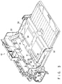
- FIG. 2 shows the appearance of the printer apparatus, which is provided with a paper sheet feeder unit 10 for feeding paper sheets one by one to a printing position where letters and image information are printed.
- a rear end 50B of the cover 50 is swingably supported round a rod 51.
- the cover 50 swings round the rod 51 to selectively open or close the opening 2 of the housing 1.
- a pair of portions 52 are erected and opposed to each other on the front portion 50T of the cover 50 to sandwich the paper feed plate 30 between them and each of the erected portions 52 has a slot 53.
- the cover 50 has a housing chamber 54 in which a paper tray 55 can be housed.
- the paper tray 55 can be pulled in the housing chamber 54 in a direction shown by a two-dot and dash line to hold the rear end portion of the stacked paper sheets when paper sheets each having a length larger than that of the paper feed plate 30 are stacked on the plate 30.
- a cover opening and closing knob 59 is attached to the front end 50T of the cover 50.
- the rear end 30B serving as a center round which the paper feed plate 30 is swung is attached to the front end 50T of the cover 50 which can be projected outside the housing 1 to a greater extent to open the opening 2.
- the length of the paper feed plate 30 can be made by far larger. Even if the height of paper sheets stacked on the paper feed plate 30 changes, therefore, the change of that angle by which the paper feed plate 30 must be swung to respond to the change of the height can be made smaller. The change of that angle at which the stacked paper sheets enter onto the separator pad 17 can be thus made extremely smaller.
- the paper feeder plate 30 When a new stack of paper sheets is to be supplied to the empty paper feeder plate 30, for example, the paper feeder plate 30 is swung round the rod and its front end 30T is further pushed down from its paper supply position shown by the two-dot and dash line in FIG. 4. In short, the front end 30T of the paper feeder plate 30 is moved in a direction Y30 in FIG. 6. When moved so, it is stopped because the face 26 of the engaging member 25 is struck against the stopper face 22 of the stopper member 21.
- the rear end 30B of the paper feeder plate 30 is swingably held in this case by the front end 50T of the cover 50 which is projected outside the housing 1 (or by the slots 53 in the front end 50T) through the pins 31.
- the angle ⁇ of the paper sheets entered can be kept almost same as the optimum one ⁇ 1 at which smooth paper feeding can be established as shown in FIG. 10A. This enables top one paper sheet to be smoothly fed in the direction Q at all times, thereby preventing paper sheet jamming from being caused.
- the stopper mechanism 20 serves to control the lower limit of the paper feeder plate 30, as shown in FIG. 6.
- the paper feeder plate 30 cannot be therefore pushed down to an excessive extent, thereby preventing an excessive number of paper sheets from being supplied and also preventing the spring 39 from being over-shrunk.
- the paper feeder plate 30 can be prevented from rapidly and severely springing up when the hand is released from the plate 30.
- the actuator 60 and others can be thus protected from being too extremely shocked and therefore from being broken. This makes it unnecessary to carefully carry out paper supply work, thereby enabling a more quick paper supply work to be attained, as compared with the conventional cases.
- the cover 50 can be lightly pushed up in the direction R1 thanks to the pushing-down force Fd caused by the forcing mechanism (7, 36).
- the pins 31 are moved along the slots then in the direction X11 when the cover 50 comes on the way of its being closed.
- the paper feeder plate 30 is housed, substantially parallel, in the erected cover 50. Even if the paper feeder plate 30 is larger in size, therefore, it can be housed in a smaller space. This makes the printer apparatus to be made smaller in size.
- the rear end 30B of the paper feeder plate 30 is swingably supported by the front end 50T of the cover 50 which serves as the outer of the housing 1 when the cover 50 is opened. Further, the spring 39 is arranged between the front end 30T of the plate 30 and the cover 50. When the cover 50 is opened, therefore, the rear end 30B of the paper feeder plate 30 is projected outside the housing 1 but the whole thereof is housed in the housing 1 when the cover 50 is closed.
- the paper sheet feeder device includes the lock mechanism for locking the paper feeder plate 30 at the paper supply position and the unlock mechanism for automatically unlocking the lock mechanism as the paper feeder roller 11 is rotated.
- the paper feeder plate 30 can be locked at the paper supply position but this lock can be automatically unlocked in response to the rotation of the paper feeder roller 11.
- An optimum number of paper sheets can be thus more quickly and easily supplied every time it is asked.
- the handling of the device can be made extremely easier.
- the stopper mechanism 20 controls the lower limit of the paper feeder plate 30 when the plate 30 is pushed down by external force added and after the lock member 41 passes over the hook member 46. This prevents the paper feeder plate 30 from being lowered to an unnecessary extent. This also previously prevents an excessive number of paper sheets from being stacked on the paper feeder plate 30. In addition, the overshrinking of the spring 39 can be prevented when the lower limit of the paper feeder plate 30 is controlled in this manner. The paper feeder plate 30 can be therefore kept not severely and rapidly sprung up, thereby preventing the actuator 60 for the paper sheet detector from being broken by the plate 30.
- the stopper mechanism 20 (21, 22) can be housed in the cut-away recess 34 of the paper feeder plate 30 not to disturb the housing of the plate 30 into the cover 50.
- the rear end 30B of the paper feeder plate 30 is provided with the pins 31, the front end 50T of the cover 50 is provided with the slots 53 which extend in the paper feeding direction when the housing 1 is kept open, and these pins 31 are slidably held in the slots 53.
- the paper feeder plate 30 is thus swingably held by the cover 50.
- the arc-shaped guide grooves 6 are formed in the housing 1, extending from above to below and to the rotating center of the cover 50, and the front end 30T of the paper feeder plate 30 is provided with the guide pins 35 which can slide along the guide grooves 6.
- the housing mechanism (31, 53, 6, 35) thus formed enables the paper feeder plate 30 to be housed, substantially parallel, in the cover 50, while using the closing operation of the cover 50.
- the present invention is not limited to the above-described embodiment but that it can be variously changed and modified within its scope and spirit.
- the paper sheet feeder device has been incorporated into the printer apparatus in the above-described case, it may be incorporated into the paper sheet cassette, for example, which can be attached to and detached from the printer apparatus itself.
- the paper sheet feeder device according to the present invention can be used, as it is, in this case.
Landscapes
- Physics & Mathematics (AREA)
- General Physics & Mathematics (AREA)
- Engineering & Computer Science (AREA)
- Mechanical Engineering (AREA)
- Sheets, Magazines, And Separation Thereof (AREA)
- Paper Feeding For Electrophotography (AREA)
Applications Claiming Priority (3)
| Application Number | Priority Date | Filing Date | Title |
|---|---|---|---|
| JP61383/94 | 1994-03-30 | ||
| JP6061383A JPH07267389A (ja) | 1994-03-30 | 1994-03-30 | 給紙装置 |
| JP6138394 | 1994-03-30 |
Publications (3)
| Publication Number | Publication Date |
|---|---|
| EP0675414A2 true EP0675414A2 (de) | 1995-10-04 |
| EP0675414A3 EP0675414A3 (de) | 1996-08-07 |
| EP0675414B1 EP0675414B1 (de) | 2001-12-19 |
Family
ID=13169603
Family Applications (1)
| Application Number | Title | Priority Date | Filing Date |
|---|---|---|---|
| EP95104602A Expired - Lifetime EP0675414B1 (de) | 1994-03-30 | 1995-03-29 | Druckvorrichtung mit einer Papierbogenzuführvorrichtung |
Country Status (5)
| Country | Link |
|---|---|
| US (1) | US5573235A (de) |
| EP (1) | EP0675414B1 (de) |
| JP (1) | JPH07267389A (de) |
| KR (1) | KR0167394B1 (de) |
| DE (1) | DE69524656T2 (de) |
Cited By (3)
| Publication number | Priority date | Publication date | Assignee | Title |
|---|---|---|---|---|
| EP0915044A3 (de) * | 1997-11-04 | 2000-02-23 | Samsung Electronics Co. Ltd. | Rückhalteplatte in einer Bogenzuführeinrichtung |
| EP1439073A1 (de) * | 2003-01-18 | 2004-07-21 | Samsung Electronics Co., Ltd. | Bilderzeugungsgerät mit verschwenkbarer Bogenstützeinrichtung |
| EP1506874A1 (de) * | 2003-08-12 | 2005-02-16 | Seiko Epson Corporation | Aufzeichnungsgerät mit automatischer Zuführeinrichtung und automatische Zuführeinrichtung |
Families Citing this family (19)
| Publication number | Priority date | Publication date | Assignee | Title |
|---|---|---|---|---|
| US5713674A (en) * | 1994-10-06 | 1998-02-03 | Pfu Limited | Paper feed method and apparatus for a printer |
| JP3247817B2 (ja) * | 1994-12-27 | 2002-01-21 | シャープ株式会社 | 給紙装置 |
| JP3363699B2 (ja) * | 1996-04-10 | 2003-01-08 | キヤノン株式会社 | シートガイド部材及びシート給送装置及び画像形成装置 |
| US5996989A (en) * | 1997-05-02 | 1999-12-07 | Lexmark International, Inc. | Sheet separator friction pad |
| KR100297762B1 (ko) * | 1998-04-01 | 2001-09-06 | 윤종용 | 인쇄기기의 용지카세트 |
| JP2002087598A (ja) * | 2000-09-08 | 2002-03-27 | Matsushita Electric Ind Co Ltd | 給紙装置 |
| US6676318B2 (en) * | 2001-10-26 | 2004-01-13 | Hewlett-Packard Development Company, L.P. | Printer media tray and method of using same |
| US6659668B2 (en) * | 2001-10-30 | 2003-12-09 | Hewlett-Packard Development Company, L.P. | Printer access door and method of using same |
| US6612562B2 (en) | 2001-12-21 | 2003-09-02 | Pitney Dowes Inc. | Method and system for feeding media to a printer |
| KR100534615B1 (ko) * | 2004-03-15 | 2005-12-07 | 삼성전자주식회사 | 접철가능한 급지카세트를 구비한 화상형성장치 |
| KR100565084B1 (ko) * | 2004-10-12 | 2006-03-30 | 삼성전자주식회사 | 수동급지대 및 이를 적용한 화상형성장치 |
| EP1834797A1 (de) * | 2006-03-17 | 2007-09-19 | Seiko Epson Corporation | Staplerpositionsänderungsvorrichtung und damit ausgerüstete Aufzeichnungs- oder Flüssigkeitsausstoßvorrichtung |
| JP2007290794A (ja) * | 2006-04-21 | 2007-11-08 | Noritsu Koki Co Ltd | シート搬送装置 |
| JP5162282B2 (ja) * | 2008-03-11 | 2013-03-13 | 京セラドキュメントソリューションズ株式会社 | 画像形成装置 |
| JP5031653B2 (ja) * | 2008-04-24 | 2012-09-19 | 京セラドキュメントソリューションズ株式会社 | 画像形成装置 |
| JP4930578B2 (ja) * | 2009-12-03 | 2012-05-16 | ブラザー工業株式会社 | 画像形成装置 |
| JP2013220862A (ja) * | 2012-04-12 | 2013-10-28 | Sumitomo Rubber Ind Ltd | 紙葉類分離パッドおよび画像形成装置 |
| JP5810124B2 (ja) * | 2013-04-15 | 2015-11-11 | 京セラドキュメントソリューションズ株式会社 | 給紙装置、およびこれを備えた画像形成装置 |
| JP6325382B2 (ja) * | 2014-07-28 | 2018-05-16 | 理想科学工業株式会社 | 扉開閉装置 |
Family Cites Families (11)
| Publication number | Priority date | Publication date | Assignee | Title |
|---|---|---|---|---|
| US4280692A (en) * | 1980-02-21 | 1981-07-28 | Nashua Corporation | Cassette with lockable lift plate |
| US4582314A (en) * | 1982-11-19 | 1986-04-15 | Brother Kogyo Kabushiki Kaisha | Paper feeding apparatus |
| JPS6366032A (ja) * | 1986-09-08 | 1988-03-24 | Ricoh Co Ltd | プリンタの自動給紙装置 |
| US5186448A (en) * | 1987-02-17 | 1993-02-16 | Canon Kabushiki Kaisha | Sheet feeding apparatus |
| JPH01321239A (ja) * | 1988-06-23 | 1989-12-27 | Canon Inc | 画像形成装置 |
| JPH02127333A (ja) * | 1988-11-02 | 1990-05-16 | Minolta Camera Co Ltd | 給紙装置 |
| DE9012932U1 (de) * | 1990-09-11 | 1990-11-15 | Develop Dr. Eisbein Gmbh & Co, 7016 Gerlingen | Papierkassette für ein Kopiergerät |
| JP2938553B2 (ja) * | 1990-10-24 | 1999-08-23 | キヤノン株式会社 | シート給送装置 |
| US5320338A (en) * | 1992-02-14 | 1994-06-14 | Mita Industrial Co., Ltd. | Cassette |
| US5437444A (en) * | 1992-03-12 | 1995-08-01 | Canon Kabushiki Kaisha | Sheet supplying apparatus |
| DE69321771T2 (de) * | 1992-06-24 | 1999-05-06 | Canon K.K., Tokio/Tokyo | Apparat zum Zuführen von Bögen |
-
1994
- 1994-03-30 JP JP6061383A patent/JPH07267389A/ja active Pending
-
1995
- 1995-03-29 DE DE69524656T patent/DE69524656T2/de not_active Expired - Fee Related
- 1995-03-29 US US08/412,763 patent/US5573235A/en not_active Expired - Fee Related
- 1995-03-29 EP EP95104602A patent/EP0675414B1/de not_active Expired - Lifetime
- 1995-03-30 KR KR1019950006985A patent/KR0167394B1/ko not_active Expired - Fee Related
Cited By (7)
| Publication number | Priority date | Publication date | Assignee | Title |
|---|---|---|---|---|
| EP0915044A3 (de) * | 1997-11-04 | 2000-02-23 | Samsung Electronics Co. Ltd. | Rückhalteplatte in einer Bogenzuführeinrichtung |
| EP1439073A1 (de) * | 2003-01-18 | 2004-07-21 | Samsung Electronics Co., Ltd. | Bilderzeugungsgerät mit verschwenkbarer Bogenstützeinrichtung |
| US7100915B2 (en) | 2003-01-18 | 2006-09-05 | Samsung Electronics Co., Ltd. | Paper feeding apparatus of image forming device |
| CN1321048C (zh) * | 2003-01-18 | 2007-06-13 | 三星电子株式会社 | 成像设备的送纸装置 |
| EP1506874A1 (de) * | 2003-08-12 | 2005-02-16 | Seiko Epson Corporation | Aufzeichnungsgerät mit automatischer Zuführeinrichtung und automatische Zuführeinrichtung |
| US7303190B2 (en) | 2003-08-12 | 2007-12-04 | Seiko Epson Corp | Recording apparatus including automatic feeding mechanism and automatic feeding mechanism |
| CN100384639C (zh) * | 2003-08-12 | 2008-04-30 | 精工爱普生株式会社 | 具有自动进给机构的记录装置和自动进给机构 |
Also Published As
| Publication number | Publication date |
|---|---|
| EP0675414B1 (de) | 2001-12-19 |
| US5573235A (en) | 1996-11-12 |
| DE69524656D1 (de) | 2002-01-31 |
| KR950026692A (ko) | 1995-10-16 |
| JPH07267389A (ja) | 1995-10-17 |
| EP0675414A3 (de) | 1996-08-07 |
| KR0167394B1 (ko) | 1999-03-30 |
| DE69524656T2 (de) | 2002-06-13 |
Similar Documents
| Publication | Publication Date | Title |
|---|---|---|
| US5573235A (en) | Paper sheet feeder device | |
| KR100226091B1 (ko) | 수동식 기록용지 삽입기구 | |
| JP5219720B2 (ja) | シート給送装置及び画像形成装置 | |
| KR100490079B1 (ko) | 용지 수납 장치, 용지 수납 장치가 제공된 용지 급송 장치및 화상 형성 장치 | |
| KR100388996B1 (ko) | 화상형성장치의 용지 카세트 | |
| JP3411119B2 (ja) | 給紙トレイ | |
| JP3193776B2 (ja) | シート材給送装置 | |
| US10757279B2 (en) | Sheet stacker and image forming apparatus | |
| JPH0740646U (ja) | シート状記録紙の収納器 | |
| JPH11334945A (ja) | バイパス給紙装置及び画像形成装置 | |
| JP2003201023A (ja) | シート収納装置及びこれを備えたシート給送装置及び画像形成装置 | |
| JPH02132023A (ja) | 画像形成装置 | |
| KR200149604Y1 (ko) | 잉크젯 프린터의 용지크기 조절장치 | |
| JPH0616247A (ja) | 複写紙カセット | |
| JP3869727B2 (ja) | 給紙装置および画像形成装置 | |
| KR950000351Y1 (ko) | 급지카세트의 저판 이동장치 | |
| JPH08133492A (ja) | 自動給紙装置 | |
| JPH0745474Y2 (ja) | 給紙装置 | |
| JPH0797076A (ja) | シート材給送装置及びこれを備える画像形成装置 | |
| JPH0611975Y2 (ja) | 両面画像形成装置のジャム処理機構 | |
| JP4324003B2 (ja) | シート材供給装置および記録装置 | |
| JP5713124B2 (ja) | 給紙装置及びそれを備えた画像記録装置 | |
| JPH061478A (ja) | シート材給送装置及び画像形成装置 | |
| JPH07267435A (ja) | 印刷装置 | |
| JPH0543115A (ja) | プリンタ |
Legal Events
| Date | Code | Title | Description |
|---|---|---|---|
| PUAI | Public reference made under article 153(3) epc to a published international application that has entered the european phase |
Free format text: ORIGINAL CODE: 0009012 |
|
| AK | Designated contracting states |
Kind code of ref document: A2 Designated state(s): DE FR GB IT |
|
| PUAL | Search report despatched |
Free format text: ORIGINAL CODE: 0009013 |
|
| AK | Designated contracting states |
Kind code of ref document: A3 Designated state(s): DE FR GB IT |
|
| 17P | Request for examination filed |
Effective date: 19970124 |
|
| 17Q | First examination report despatched |
Effective date: 19990203 |
|
| RAP1 | Party data changed (applicant data changed or rights of an application transferred) |
Owner name: TOSHIBA TEC KABUSHIKI KAISHA |
|
| GRAG | Despatch of communication of intention to grant |
Free format text: ORIGINAL CODE: EPIDOS AGRA |
|
| RTI1 | Title (correction) |
Free format text: PRINTER APPARATUS WITH A PAPER SHEET FEEDER DEVICE |
|
| GRAG | Despatch of communication of intention to grant |
Free format text: ORIGINAL CODE: EPIDOS AGRA |
|
| GRAH | Despatch of communication of intention to grant a patent |
Free format text: ORIGINAL CODE: EPIDOS IGRA |
|
| GRAH | Despatch of communication of intention to grant a patent |
Free format text: ORIGINAL CODE: EPIDOS IGRA |
|
| GRAA | (expected) grant |
Free format text: ORIGINAL CODE: 0009210 |
|
| AK | Designated contracting states |
Kind code of ref document: B1 Designated state(s): DE FR GB IT |
|
| REG | Reference to a national code |
Ref country code: GB Ref legal event code: IF02 |
|
| REF | Corresponds to: |
Ref document number: 69524656 Country of ref document: DE Date of ref document: 20020131 |
|
| ET | Fr: translation filed | ||
| PLBE | No opposition filed within time limit |
Free format text: ORIGINAL CODE: 0009261 |
|
| STAA | Information on the status of an ep patent application or granted ep patent |
Free format text: STATUS: NO OPPOSITION FILED WITHIN TIME LIMIT |
|
| 26N | No opposition filed | ||
| PGFP | Annual fee paid to national office [announced via postgrant information from national office to epo] |
Ref country code: FR Payment date: 20040309 Year of fee payment: 10 |
|
| PGFP | Annual fee paid to national office [announced via postgrant information from national office to epo] |
Ref country code: GB Payment date: 20040324 Year of fee payment: 10 |
|
| PGFP | Annual fee paid to national office [announced via postgrant information from national office to epo] |
Ref country code: DE Payment date: 20040408 Year of fee payment: 10 |
|
| PG25 | Lapsed in a contracting state [announced via postgrant information from national office to epo] |
Ref country code: IT Free format text: LAPSE BECAUSE OF NON-PAYMENT OF DUE FEES Effective date: 20050329 Ref country code: GB Free format text: LAPSE BECAUSE OF NON-PAYMENT OF DUE FEES Effective date: 20050329 |
|
| PG25 | Lapsed in a contracting state [announced via postgrant information from national office to epo] |
Ref country code: DE Free format text: LAPSE BECAUSE OF NON-PAYMENT OF DUE FEES Effective date: 20051001 |
|
| GBPC | Gb: european patent ceased through non-payment of renewal fee |
Effective date: 20050329 |
|
| PG25 | Lapsed in a contracting state [announced via postgrant information from national office to epo] |
Ref country code: FR Free format text: LAPSE BECAUSE OF NON-PAYMENT OF DUE FEES Effective date: 20051130 |
|
| REG | Reference to a national code |
Ref country code: FR Ref legal event code: ST Effective date: 20051130 |