EP0675512A1 - Système de connection électrique pour le dispositif de dérivation d'un tube cathodique - Google Patents
Système de connection électrique pour le dispositif de dérivation d'un tube cathodique Download PDFInfo
- Publication number
- EP0675512A1 EP0675512A1 EP95104020A EP95104020A EP0675512A1 EP 0675512 A1 EP0675512 A1 EP 0675512A1 EP 95104020 A EP95104020 A EP 95104020A EP 95104020 A EP95104020 A EP 95104020A EP 0675512 A1 EP0675512 A1 EP 0675512A1
- Authority
- EP
- European Patent Office
- Prior art keywords
- terminal
- header
- connector
- cavities
- yoke
- Prior art date
- Legal status (The legal status is an assumption and is not a legal conclusion. Google has not performed a legal analysis and makes no representation as to the accuracy of the status listed.)
- Granted
Links
- 239000004020 conductor Substances 0.000 claims abstract description 19
- 230000013011 mating Effects 0.000 claims description 6
- 230000000295 complement effect Effects 0.000 claims description 2
- 238000002788 crimping Methods 0.000 claims description 2
- 210000002105 tongue Anatomy 0.000 description 7
- 238000003780 insertion Methods 0.000 description 2
- 230000037431 insertion Effects 0.000 description 2
- 229910000679 solder Inorganic materials 0.000 description 2
- 238000004891 communication Methods 0.000 description 1
- 238000013461 design Methods 0.000 description 1
- 239000003989 dielectric material Substances 0.000 description 1
- 239000000463 material Substances 0.000 description 1
- 239000007769 metal material Substances 0.000 description 1
- 238000000034 method Methods 0.000 description 1
- 238000012986 modification Methods 0.000 description 1
- 230000004048 modification Effects 0.000 description 1
- 230000002093 peripheral effect Effects 0.000 description 1
Images



Classifications
-
- H—ELECTRICITY
- H01—ELECTRIC ELEMENTS
- H01R—ELECTRICALLY-CONDUCTIVE CONNECTIONS; STRUCTURAL ASSOCIATIONS OF A PLURALITY OF MUTUALLY-INSULATED ELECTRICAL CONNECTING ELEMENTS; COUPLING DEVICES; CURRENT COLLECTORS
- H01R9/00—Structural associations of a plurality of mutually-insulated electrical connecting elements, e.g. terminal strips or terminal blocks; Terminals or binding posts mounted upon a base or in a case; Bases therefor
- H01R9/03—Connectors arranged to contact a plurality of the conductors of a multiconductor cable, e.g. tapping connections
-
- H—ELECTRICITY
- H01—ELECTRIC ELEMENTS
- H01R—ELECTRICALLY-CONDUCTIVE CONNECTIONS; STRUCTURAL ASSOCIATIONS OF A PLURALITY OF MUTUALLY-INSULATED ELECTRICAL CONNECTING ELEMENTS; COUPLING DEVICES; CURRENT COLLECTORS
- H01R13/00—Details of coupling devices of the kinds covered by groups H01R12/70 or H01R24/00 - H01R33/00
- H01R13/40—Securing contact members in or to a base or case; Insulating of contact members
- H01R13/42—Securing in a demountable manner
- H01R13/428—Securing in a demountable manner by resilient locking means on the contact members; by locking means on resilient contact members
- H01R13/432—Securing in a demountable manner by resilient locking means on the contact members; by locking means on resilient contact members by stamped-out resilient tongue snapping behind shoulder in base or case
-
- H—ELECTRICITY
- H01—ELECTRIC ELEMENTS
- H01F—MAGNETS; INDUCTANCES; TRANSFORMERS; SELECTION OF MATERIALS FOR THEIR MAGNETIC PROPERTIES
- H01F5/00—Coils
- H01F5/04—Arrangements of electric connections to coils, e.g. leads
-
- H—ELECTRICITY
- H01—ELECTRIC ELEMENTS
- H01R—ELECTRICALLY-CONDUCTIVE CONNECTIONS; STRUCTURAL ASSOCIATIONS OF A PLURALITY OF MUTUALLY-INSULATED ELECTRICAL CONNECTING ELEMENTS; COUPLING DEVICES; CURRENT COLLECTORS
- H01R13/00—Details of coupling devices of the kinds covered by groups H01R12/70 or H01R24/00 - H01R33/00
- H01R13/02—Contact members
- H01R13/26—Pin or blade contacts for sliding co-operation on one side only
-
- H—ELECTRICITY
- H01—ELECTRIC ELEMENTS
- H01R—ELECTRICALLY-CONDUCTIVE CONNECTIONS; STRUCTURAL ASSOCIATIONS OF A PLURALITY OF MUTUALLY-INSULATED ELECTRICAL CONNECTING ELEMENTS; COUPLING DEVICES; CURRENT COLLECTORS
- H01R2107/00—Four or more poles
-
- H—ELECTRICITY
- H01—ELECTRIC ELEMENTS
- H01R—ELECTRICALLY-CONDUCTIVE CONNECTIONS; STRUCTURAL ASSOCIATIONS OF A PLURALITY OF MUTUALLY-INSULATED ELECTRICAL CONNECTING ELEMENTS; COUPLING DEVICES; CURRENT COLLECTORS
- H01R24/00—Two-part coupling devices, or either of their cooperating parts, characterised by their overall structure
- H01R24/28—Coupling parts carrying pins, blades or analogous contacts and secured only to wire or cable
Definitions
- This invention generally relates to the art of electrical connectors and, particularly, to an electrical connector system located at the rear of a video display tube yoke.
- Video display tube yokes normally have some form of electrical connector, such as a header connector, mounted on the rear or back side of the yoke.
- the header has a plurality of relatively stiff terminal pins to which the conductors of a plurality of electrical wires are soldered, the wires providing electrical power to the yoke and/or the components thereof.
- a separate dielectric cover usually is mounted over the header connector, particularly over the terminal pins, to protect the pins and prevent engagement thereof with extraneous objects.
- the opposite ends of the wires often have one or more electrical connectors terminated thereto.
- the present invention is directed to solving these problems by an electrical connector system adapted for use with video display tube yoke header connectors of conventional design and configuration.
- An object, therefore, of the invention is to provide a new and improved electrical connector system for a video display tube yoke.
- a header is mounted on the yoke and includes a header body and a plurality of stiff terminal pins projecting therefrom and terminated to appropriate leads from the yoke.
- a connector is provided for mating with the header and includes a dielectric housing having a plurality of terminal-receiving cavities. A plurality of pin-receiving passages communicate with the cavities. A plurality of terminals are received in the cavities. Each terminal includes a terminal portion adapted to be terminated to a wire conductor, and a trap portion aligned with one of the pin-receiving passages and adapted to receive and trap one of the stiff terminal pins of the header. A plurality of wire conductors are terminated to the terminals.
- Complementary interengaging latch means are provided between the header and the connector to hold the header in mated condition.
- the connector also includes standoff means for engaging the header body to properly space the connector housing from the header body.
- standoff means for engaging the header body to properly space the connector housing from the header body.
- the terminal portions of the terminals are provided by crimp sections for crimping termination to the wire conductors.
- the pin-receiving passages intersect the terminal-receiving cavities generally perpendicularly thereto to provide a right-angle connector configuration. In another embodiment of the invention, the pin-receiving passages intersect the terminal-receiving cavities generally parallel thereto to provide an in-line connector configuration.
- Figure 1 shows a connector system for a video display tube yoke, according to the prior art.
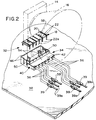
- Figures 2-8 show one embodiment of an electrical connector system for a video display tube yoke, according to the invention.
- Figures 9 and 10 show a second embodiment of an electrical connector system for a video display tube yoke, according to the invention.
- the difference between the first embodiment of Figures 2-8 and the second embodiment of Figures 9 and 10 is that the first embodiment has a "right-angle" connector configuration, and the second embodiment has a "in-line” connector configuration, all of which will be apparent hereinafter.
- an electrical connector system is shown according to the prior art as applied to a collar 14 at the rear of a video display tube yoke 16.
- the system includes a header connector, generally designated 18, which includes a generally flat dielectric body 20.
- a plurality of generally U-shaped terminals 22 are mounted on body 20, with leg portions 22a and 22b projecting along opposite side edges of the body and with loop portions 22c first passing through slots in body 20 and then expanded to hold the terminals 22 to body 20.
- Legs 22a and 22b form relatively stiff terminal pins of the header. Leads from the yoke are soldered to terminal pins 22a.
- Connector system 12 of the prior art shown in Figure 1 also includes a plurality of electrical wires 26 where each wire inner conductor is "hard-wired” or soldered to loop portions 22c of terminals 22. The opposite ends of the wires are terminated to one or more electrical connectors 28. These connectors mate with other connectors which may be surface mountable to a printed circuit board 29. Lastly, a separate cover 30 is mounted over header 18 to protect the header, particularly to protect and enclose terminal pins 22a and 22b along with their terminations to the yoke leads and conductors of wires 26.
- Figure 2 shows one embodiment of an electrical connector system, generally designated 32, according to the invention.
- the system does not make any modifications to header 18, including body 20, terminals 22, stiff terminal pins 22a and 22b, as well as the manner in which the leads from the yoke are soldered to legs 22b of the terminals.
- the invention incorporates a connector, generally designated 34, for mating with header 18.
- a plurality of conductors of wires 36 leading from a printed circuit board 38 are terminated within connector 34, as will be described hereinafter.
- the conductors are connected to circuit traces 39a on the printed circuit board by being soldered to circuit pads 39 as shown in Figure 2 or by being connected to terminals which mate with terminals mounted to the circuit pads 39 of the printed circuit board.
- connector 34 includes a dielectric housing, generally designated 40, which includes a plurality of terminal-receiving cavities 42.
- the housing has a box-like section 44 having peripheral side flanges 46 which substantially embrace header 18 and particularly protect the stiff terminal pins 22a and 22b of the header.
- Housing 40 further includes a plurality of pin-receiving passages 48 which are in communication with terminal-receiving cavities 42.
- connector 34 provides a "right-angle" connector configuration.
- pin-receiving passages 48 extend through housing 40 and intersect terminal-receiving cavities 42 generally perpendicularly thereto to provide the right-angle connector configuration.
- connector housing 40 includes a pair of latch arms 50 having hooked distal ends 52.
- the entire housing is unitarily molded in one-piece of dielectric material such as plastic or the like. Therefore, latch arms 50 are inherently flexible.
- chamfered surfaces 52a on hooked distal ends 52 of the latch arms bias the arms outwardly until the hooked distal ends snap beneath header body 20.
- a pair of flanges 54 project inwardly within the box-like section 44 of connector housing 40.
- the flanges have integral abutment bosses 56 on the insides thereof.
- the distal ends of the flanges project into holes 58 in header body 20, and abutment bosses 56 abut against the top surface of the header body to provide "standoff" means to properly space the connector housing from the connector body when hooked distal ends 52 of latch arms 50 snappingly mate connector 40 with header 18.
- a plurality of terminals are received within terminal-receiving cavities 42 of connector housing 40.
- Each terminal includes a terminal portion 62 adapted to be terminated to a respective wire conductor 36.
- the terminal portion is a crimp section adapted to be crimped onto the inner conductor of an electrical wire.
- the terminal also includes a blade section 64 which is the section of the terminal that is inserted into a respective one of the terminal-receiving cavities 42.
- the terminal may be stamped and formed of sheet metal material, with blade section 64 being generally planar.
- a latch tongue 66 is formed out of the blade section and faces or "points" in a direction opposite the insertion direction of the terminal as indicated by arrow "A". Once inserted into its respective terminal-receiving cavity, the terminal is precluded from being pulled out of the cavity by latch tongue 66 which will dig into the plastic material of the connector housing upon the application of forces on the terminal opposite the insertion direction of arrow "A".
- Each terminal 60 includes a trap portion in the form of a trap tongue 68 which is formed out of planar blade section 64.
- a bent distal end 68a of trap tongue 68 is aligned with a respective pin-receiving passage 48.
- stiff terminal pins 22a of header 18 move into cut-out areas 70 of terminals 60 and become trapped by ends 68a of trap tongues 68.
- Figure 8 shows that terminals 22 are secured to header body 20 by means of loop portions 22c secured within appropriate slots in the body. Leads 71 are also shown from the video display tube yoke hard wired to terminal pins 22b.
- Figures 9 and 10 show an alternate embodiment of the invention wherein an "in-line" connector, generally designated 72, is adapted for mating with header 18.
- In-line connector 72 includes a plurality of in-line terminals, generally designated 74. Again, the terminal includes a crimp-type terminal portion 76 and a trap portion 78.
- a respective one of the stiff terminal pins 22a of header 18 is inserted into terminal 74 (Fig. 9) in the direction of arrow "B" (Fig. 10). The pin becomes trapped behind a trap tongue 80.
- a latch tongue 81 secures the terminal within the connector.
- Figure 10 shows that connector 72 again has a dielectric housing, generally designated 82, which includes a plurality of terminal-receiving cavities 84 for receiving terminals 74. With connector 72, a plurality of pin-receiving passages 86 are generally parallel to terminal-receiving cavities 84 to provide an in-line connector configuration.
- the connector housing has latch means and standoff means as described above in relation to the embodiment of Figures 2-8.
Landscapes
- Engineering & Computer Science (AREA)
- Power Engineering (AREA)
- Connector Housings Or Holding Contact Members (AREA)
- Coupling Device And Connection With Printed Circuit (AREA)
- Details Of Connecting Devices For Male And Female Coupling (AREA)
Applications Claiming Priority (2)
| Application Number | Priority Date | Filing Date | Title |
|---|---|---|---|
| US08/220,083 US5423698A (en) | 1994-03-30 | 1994-03-30 | Electrical connector system for a video display tube yoke |
| US220083 | 1994-03-30 |
Publications (2)
| Publication Number | Publication Date |
|---|---|
| EP0675512A1 true EP0675512A1 (fr) | 1995-10-04 |
| EP0675512B1 EP0675512B1 (fr) | 1997-02-05 |
Family
ID=22821981
Family Applications (1)
| Application Number | Title | Priority Date | Filing Date |
|---|---|---|---|
| EP95104020A Expired - Lifetime EP0675512B1 (fr) | 1994-03-30 | 1995-03-18 | Système de connection électrique pour un bloc de déviation d'un tube d'afficheurvidéo |
Country Status (6)
| Country | Link |
|---|---|
| US (1) | US5423698A (fr) |
| EP (1) | EP0675512B1 (fr) |
| JP (1) | JP2799491B2 (fr) |
| KR (1) | KR0146974B1 (fr) |
| DE (1) | DE69500148T2 (fr) |
| MY (1) | MY130192A (fr) |
Families Citing this family (3)
| Publication number | Priority date | Publication date | Assignee | Title |
|---|---|---|---|---|
| JP2006047371A (ja) * | 2004-07-30 | 2006-02-16 | Orion Denki Kk | 表示管を備えた電子機器 |
| US7304157B2 (en) * | 2004-09-28 | 2007-12-04 | Bristol-Myers Squibb Company | Efficient synthesis of 4,5-dihydro-pyrazolo[3,4-c]pyrid-2-ones |
| US10084253B2 (en) * | 2016-03-24 | 2018-09-25 | Lear Corporation | Electrical unit and header retention system therefor |
Citations (8)
| Publication number | Priority date | Publication date | Assignee | Title |
|---|---|---|---|---|
| DE1293278B (de) * | 1958-06-02 | 1969-04-24 | Telemecanique Sa | Schaltgeraetetafel |
| US3706954A (en) * | 1970-12-28 | 1972-12-19 | Molex Inc | Connector and arrangement for circuit board assembly therewith |
| JPS5325829A (en) * | 1976-08-20 | 1978-03-10 | Matsushita Electric Industrial Co Ltd | Method of making nonnaqueous electrolyte batteries |
| US4445101A (en) * | 1981-07-21 | 1984-04-24 | Victor Company Of Japan, Limited | Deflecting yoke assembly for making a trapezoidal raster |
| JPS60249302A (ja) * | 1984-05-24 | 1985-12-10 | Canon Inc | コイルボビン |
| US4673906A (en) * | 1986-06-03 | 1987-06-16 | Zenith Electronics Corporation | CRT deflection yoke with rigidifying means |
| US4720646A (en) * | 1985-12-03 | 1988-01-19 | Mitsubishi Denki Kabushiki Kaisha | Connection terminal assembly for stator coil |
| GB2269477A (en) * | 1992-08-06 | 1994-02-09 | Mitsubishi Electric Corp | CRT deflection yoke with printed circuit board |
Family Cites Families (13)
| Publication number | Priority date | Publication date | Assignee | Title |
|---|---|---|---|---|
| US3777301A (en) * | 1972-11-29 | 1973-12-04 | Molex Inc | Terminals and connectors for interconnecting conductors and male contacts |
| FR2246991B1 (fr) * | 1973-10-08 | 1978-03-31 | Pfeuty Alain | |
| GB1539033A (en) * | 1975-04-18 | 1979-01-24 | Rists Wires & Cables Ltd | Electrical connector |
| US4740167A (en) * | 1984-03-02 | 1988-04-26 | Amp Incorporated | Power distribution unit for modular wall panels |
| DE3526664C2 (de) * | 1984-08-06 | 1995-02-16 | Amp Inc | Elektrischer Steckverbinder |
| JPS61188271U (fr) * | 1985-05-14 | 1986-11-22 | ||
| JPS6210885A (ja) * | 1985-07-08 | 1987-01-19 | 日本航空電子工業株式会社 | コネクタ装置 |
| JPS63165753U (fr) * | 1987-04-17 | 1988-10-28 | ||
| JP2896783B2 (ja) * | 1989-03-01 | 1999-05-31 | 日本航空電子工業株式会社 | コネクタハウジングの二重ロック構造 |
| US5004432A (en) * | 1989-10-02 | 1991-04-02 | Raychem Corporation | Electrical connector |
| US5204565A (en) * | 1990-11-21 | 1993-04-20 | Jidosha Denki Kogyo Kabushiki Kaisha | Small-sized electric motor with connector for power supply |
| US5078609A (en) * | 1991-04-15 | 1992-01-07 | Molex Incorporated | Plural jack connector module |
| US5269699A (en) * | 1992-06-09 | 1993-12-14 | Molex Incorporated | Lockable electrical connector assembly |
-
1994
- 1994-03-30 US US08/220,083 patent/US5423698A/en not_active Expired - Fee Related
-
1995
- 1995-02-13 MY MYPI95000335A patent/MY130192A/en unknown
- 1995-03-18 EP EP95104020A patent/EP0675512B1/fr not_active Expired - Lifetime
- 1995-03-18 DE DE69500148T patent/DE69500148T2/de not_active Expired - Fee Related
- 1995-03-23 JP JP7090311A patent/JP2799491B2/ja not_active Expired - Lifetime
- 1995-03-29 KR KR1019950006874A patent/KR0146974B1/ko not_active Expired - Fee Related
Patent Citations (8)
| Publication number | Priority date | Publication date | Assignee | Title |
|---|---|---|---|---|
| DE1293278B (de) * | 1958-06-02 | 1969-04-24 | Telemecanique Sa | Schaltgeraetetafel |
| US3706954A (en) * | 1970-12-28 | 1972-12-19 | Molex Inc | Connector and arrangement for circuit board assembly therewith |
| JPS5325829A (en) * | 1976-08-20 | 1978-03-10 | Matsushita Electric Industrial Co Ltd | Method of making nonnaqueous electrolyte batteries |
| US4445101A (en) * | 1981-07-21 | 1984-04-24 | Victor Company Of Japan, Limited | Deflecting yoke assembly for making a trapezoidal raster |
| JPS60249302A (ja) * | 1984-05-24 | 1985-12-10 | Canon Inc | コイルボビン |
| US4720646A (en) * | 1985-12-03 | 1988-01-19 | Mitsubishi Denki Kabushiki Kaisha | Connection terminal assembly for stator coil |
| US4673906A (en) * | 1986-06-03 | 1987-06-16 | Zenith Electronics Corporation | CRT deflection yoke with rigidifying means |
| GB2269477A (en) * | 1992-08-06 | 1994-02-09 | Mitsubishi Electric Corp | CRT deflection yoke with printed circuit board |
Non-Patent Citations (2)
| Title |
|---|
| PATENT ABSTRACTS OF JAPAN vol. 10, no. 113 (E - 399)<2170> 26 April 1986 (1986-04-26) * |
| PATENT ABSTRACTS OF JAPAN vol. 18, no. 139 (E - 1519) 8 March 1994 (1994-03-08) * |
Also Published As
| Publication number | Publication date |
|---|---|
| MY130192A (en) | 2007-06-29 |
| KR950028226A (ko) | 1995-10-18 |
| DE69500148D1 (de) | 1997-03-20 |
| KR0146974B1 (ko) | 1998-09-15 |
| JPH07282913A (ja) | 1995-10-27 |
| US5423698A (en) | 1995-06-13 |
| JP2799491B2 (ja) | 1998-09-17 |
| DE69500148T2 (de) | 1997-08-28 |
| EP0675512B1 (fr) | 1997-02-05 |
Similar Documents
| Publication | Publication Date | Title |
|---|---|---|
| EP1428297B1 (fr) | Connecteur et borne électriques d'automobile pour courant fort | |
| KR100231122B1 (ko) | 개선된 배치 수단을 갖는 전기 커넥터 | |
| US4416504A (en) | Contact with dual cantilevered arms with narrowed, complimentary tip portions | |
| EP0600120A1 (fr) | Système de connecteur électrique à fiche et prise | |
| EP0630080A2 (fr) | Fiche modulaire téléphonique monté sur une plaquette à circuits imprimés | |
| EP0624928B1 (fr) | Ensemble connecteur électrique blindé | |
| US5788520A (en) | Connector shorting bar retention | |
| US6299476B1 (en) | Electrical connector with a flexible circuit and rigidizer subassembly and a spring | |
| US6305980B2 (en) | Cable end connector having accurately positioned connection terminal therein | |
| EP0637855A2 (fr) | Connecteur électrique avec système de verrouillage pour des terminaux | |
| KR100204373B1 (ko) | 편평 케이블을 회로 기판에 상호 접속시키기 위한 전기커넥터 조립체 | |
| US6010377A (en) | High contact force pin-receiving electrical terminal | |
| US5133672A (en) | Insulation displacement terminal | |
| EP0496276B1 (fr) | Borne et connecteur à coinçage pour conducteur électrique | |
| EP0014037A1 (fr) | Connecteur électrique pour un câble plat | |
| US6231393B1 (en) | Electrical connector | |
| US5437567A (en) | Female electrical terminal | |
| US5975955A (en) | Shielded electrical connector assembly with grounding system | |
| US4737888A (en) | Receptacle assembly and mounting bracket for circuit board connections | |
| US6293829B1 (en) | Electrical connector with wire management system | |
| US6200163B1 (en) | Electrical connector including means for terminating the shield of a high speed cable | |
| US6186828B1 (en) | Electrical connector including coaxial cable management system | |
| US5423698A (en) | Electrical connector system for a video display tube yoke | |
| EP0378337A2 (fr) | Pièce terminale pour haut-parleur à coinçage du fil | |
| EP0510264B1 (fr) | Système de connexion pour des câbles coaxiales |
Legal Events
| Date | Code | Title | Description |
|---|---|---|---|
| PUAI | Public reference made under article 153(3) epc to a published international application that has entered the european phase |
Free format text: ORIGINAL CODE: 0009012 |
|
| 17P | Request for examination filed |
Effective date: 19950519 |
|
| AK | Designated contracting states |
Kind code of ref document: A1 Designated state(s): DE FR GB IT |
|
| 17Q | First examination report despatched |
Effective date: 19950911 |
|
| GRAG | Despatch of communication of intention to grant |
Free format text: ORIGINAL CODE: EPIDOS AGRA |
|
| GRAH | Despatch of communication of intention to grant a patent |
Free format text: ORIGINAL CODE: EPIDOS IGRA |
|
| GRAH | Despatch of communication of intention to grant a patent |
Free format text: ORIGINAL CODE: EPIDOS IGRA |
|
| ITF | It: translation for a ep patent filed | ||
| GRAA | (expected) grant |
Free format text: ORIGINAL CODE: 0009210 |
|
| AK | Designated contracting states |
Kind code of ref document: B1 Designated state(s): DE FR GB IT |
|
| ET | Fr: translation filed | ||
| REF | Corresponds to: |
Ref document number: 69500148 Country of ref document: DE Date of ref document: 19970320 |
|
| PLBE | No opposition filed within time limit |
Free format text: ORIGINAL CODE: 0009261 |
|
| STAA | Information on the status of an ep patent application or granted ep patent |
Free format text: STATUS: NO OPPOSITION FILED WITHIN TIME LIMIT |
|
| 26N | No opposition filed | ||
| PGFP | Annual fee paid to national office [announced via postgrant information from national office to epo] |
Ref country code: GB Payment date: 19990203 Year of fee payment: 5 |
|
| PGFP | Annual fee paid to national office [announced via postgrant information from national office to epo] |
Ref country code: FR Payment date: 19990302 Year of fee payment: 5 |
|
| PGFP | Annual fee paid to national office [announced via postgrant information from national office to epo] |
Ref country code: DE Payment date: 19990330 Year of fee payment: 5 |
|
| PG25 | Lapsed in a contracting state [announced via postgrant information from national office to epo] |
Ref country code: GB Free format text: LAPSE BECAUSE OF NON-PAYMENT OF DUE FEES Effective date: 20000318 |
|
| GBPC | Gb: european patent ceased through non-payment of renewal fee |
Effective date: 20000318 |
|
| PG25 | Lapsed in a contracting state [announced via postgrant information from national office to epo] |
Ref country code: FR Free format text: LAPSE BECAUSE OF NON-PAYMENT OF DUE FEES Effective date: 20001130 |
|
| REG | Reference to a national code |
Ref country code: FR Ref legal event code: ST |
|
| PG25 | Lapsed in a contracting state [announced via postgrant information from national office to epo] |
Ref country code: DE Free format text: LAPSE BECAUSE OF NON-PAYMENT OF DUE FEES Effective date: 20010103 |
|
| PG25 | Lapsed in a contracting state [announced via postgrant information from national office to epo] |
Ref country code: IT Free format text: LAPSE BECAUSE OF NON-PAYMENT OF DUE FEES;WARNING: LAPSES OF ITALIAN PATENTS WITH EFFECTIVE DATE BEFORE 2007 MAY HAVE OCCURRED AT ANY TIME BEFORE 2007. THE CORRECT EFFECTIVE DATE MAY BE DIFFERENT FROM THE ONE RECORDED. Effective date: 20050318 |