EP0675603B1 - Verfahren zur Detektierung eines Absolutpositionssignals und Absolutpositionsgeber - Google Patents
Verfahren zur Detektierung eines Absolutpositionssignals und Absolutpositionsgeber Download PDFInfo
- Publication number
- EP0675603B1 EP0675603B1 EP94309908A EP94309908A EP0675603B1 EP 0675603 B1 EP0675603 B1 EP 0675603B1 EP 94309908 A EP94309908 A EP 94309908A EP 94309908 A EP94309908 A EP 94309908A EP 0675603 B1 EP0675603 B1 EP 0675603B1
- Authority
- EP
- European Patent Office
- Prior art keywords
- signal
- bit
- incremental
- counting circuit
- absolute position
- Prior art date
- Legal status (The legal status is an assumption and is not a legal conclusion. Google has not performed a legal analysis and makes no representation as to the accuracy of the status listed.)
- Expired - Lifetime
Links
- 238000000034 method Methods 0.000 title claims description 13
- 230000007704 transition Effects 0.000 claims description 4
- 238000001514 detection method Methods 0.000 description 5
- 238000006243 chemical reaction Methods 0.000 description 1
- 238000010586 diagram Methods 0.000 description 1
- 238000006073 displacement reaction Methods 0.000 description 1
- 230000000694 effects Effects 0.000 description 1
Images
Classifications
-
- G—PHYSICS
- G01—MEASURING; TESTING
- G01D—MEASURING NOT SPECIALLY ADAPTED FOR A SPECIFIC VARIABLE; ARRANGEMENTS FOR MEASURING TWO OR MORE VARIABLES NOT COVERED IN A SINGLE OTHER SUBCLASS; TARIFF METERING APPARATUS; MEASURING OR TESTING NOT OTHERWISE PROVIDED FOR
- G01D5/00—Mechanical means for transferring the output of a sensing member; Means for converting the output of a sensing member to another variable where the form or nature of the sensing member does not constrain the means for converting; Transducers not specially adapted for a specific variable
- G01D5/12—Mechanical means for transferring the output of a sensing member; Means for converting the output of a sensing member to another variable where the form or nature of the sensing member does not constrain the means for converting; Transducers not specially adapted for a specific variable using electric or magnetic means
- G01D5/244—Mechanical means for transferring the output of a sensing member; Means for converting the output of a sensing member to another variable where the form or nature of the sensing member does not constrain the means for converting; Transducers not specially adapted for a specific variable using electric or magnetic means influencing characteristics of pulses or pulse trains; generating pulses or pulse trains
- G01D5/245—Mechanical means for transferring the output of a sensing member; Means for converting the output of a sensing member to another variable where the form or nature of the sensing member does not constrain the means for converting; Transducers not specially adapted for a specific variable using electric or magnetic means influencing characteristics of pulses or pulse trains; generating pulses or pulse trains using a variable number of pulses in a train
- G01D5/2454—Encoders incorporating incremental and absolute signals
- G01D5/2455—Encoders incorporating incremental and absolute signals with incremental and absolute tracks on the same encoder
-
- H—ELECTRICITY
- H03—ELECTRONIC CIRCUITRY
- H03M—CODING; DECODING; CODE CONVERSION IN GENERAL
- H03M1/00—Analogue/digital conversion; Digital/analogue conversion
- H03M1/12—Analogue/digital converters
- H03M1/22—Analogue/digital converters pattern-reading type
- H03M1/24—Analogue/digital converters pattern-reading type using relatively movable reader and disc or strip
- H03M1/28—Analogue/digital converters pattern-reading type using relatively movable reader and disc or strip with non-weighted coding
- H03M1/282—Analogue/digital converters pattern-reading type using relatively movable reader and disc or strip with non-weighted coding of the pattern-shifting type, e.g. pseudo-random chain code
-
- H—ELECTRICITY
- H03—ELECTRONIC CIRCUITRY
- H03M—CODING; DECODING; CODE CONVERSION IN GENERAL
- H03M1/00—Analogue/digital conversion; Digital/analogue conversion
- H03M1/12—Analogue/digital converters
- H03M1/22—Analogue/digital converters pattern-reading type
- H03M1/24—Analogue/digital converters pattern-reading type using relatively movable reader and disc or strip
- H03M1/28—Analogue/digital converters pattern-reading type using relatively movable reader and disc or strip with non-weighted coding
- H03M1/30—Analogue/digital converters pattern-reading type using relatively movable reader and disc or strip with non-weighted coding incremental
- H03M1/308—Analogue/digital converters pattern-reading type using relatively movable reader and disc or strip with non-weighted coding incremental with additional pattern means for determining the absolute position, e.g. reference marks
Definitions
- the present invention relates to an absolute position encoding method and an absolute position encoder, and more particularly, to a new improvement for obtaining an absolute position encoder in a structure almost similar to an incremental position encoder, and for enabling an AC servo motor to immediately start up through detecting the positions of magnetic poles in the AC servo motor at power ON.
- n-bit positional signals each use one-track type n-bit positional signals, detect said n-bit positional signals through disposing n light receiving elements corresponding to the n bits toward the track (toward the circumference), and output the n-bit positional signals as positional signals accompanying displacement of an input axis position of the encoder.
- the object of the present invention is to solve the above issues, and in particular, objects of the present invention are to obtain an absolute position encoding method and an absolute position encoder in a structure almost similar to an incremental encoder, and to enable an AC servo motor to immediately start up through detecting positions of magnetic poles in the AC servo motor when power is first turned on.
- An absolute position encoding method using an n-bit positional signal provided along a first track of a code plate and using an incremental signal having transitions corresponding to the pitch of said n-bit signal and provided along a second track of said code plate said absolute position encoding method comprising the steps of providing on said code plate a third track containing an m-bit signal where said m-bit signal is representative of the magnetic pole positions of the rotating member of an AC servo motor; reading said m-bit signal at the time of turning power ON and loading said read m-bit signal into a counting circuit; subsequently reading said n-bit signal from said code plate and loading said read n-bit signal into said counting circuit; and incrementing or decrementing said loaded n-bit signal in accordance with signals read from said incremental track to provide the encoded angular position of said rotating member of said servo motor.
- this method further comprises: using a latch circuit to read said n-bit signal at the instants when said incremental signal changes its value; and loading said read n-bit signal through a serial to parallel signal converter into said counting circuit.
- the counting circuit is caused to count upwards in response to said incremental signals for a first direction of rotation of said servo motor, and to count downwards in response to said incremental signals for a second direction of rotation of said servo motor.
- An absolute encoder for providing absolute position signal using an n-bit positional signal formed on one track of a code plate, an incremental signal having transitions corresponding to the pitch of said n-bit signal and formed on another track of said code plate, and an m-bit signal representative of the magnetic pole positions of a rotating member of an AC servo motor formed on another track of said code plate, said encoder comprising an UP/DOWN circuit having an input coupled to means for reading said incremental signal, a counting circuit having an input coupled to an output of said UP/DOWN circuit, a latch circuit having inputs coupled to means for reading said n-bit signal and said incremental signal, a serial to parallel signal converter having an input coupled to an output of said latch circuit, a pure binary signal converter and a data selector coupled between an output of said serial to parallel signal convener and input means for said counting circuit, and a load command circuit, interconnecting said pure binary signal converter and a source of power ON/OFF signal with said data selector and said counting circuit, for controlling loading of said m-bit signal into the counting
- an absolute position encoding method and an absolute position encoder In an absolute position encoding method and an absolute position encoder according to the present invention, at power ON, a m-bit positional signal that is a detection signal of magnetic poles in an AC servo motor provided on a code plate is read into the data selector, and this m-bit positional signal from the data selector is read into the counting circuit, that is, the first load is performed. Next, with this m-bit positional signal, the AC servo motor is minutely (360°/2 n ) rotated, a n-bit positional signal is scanned and detected with an incremental signal corresponding to these n bits, using a latch circuit, and the second load is performed setting this n-bit positional signal as an absolute value against said counting circuit.
- the encoder After completion of the loading of the n-bit signal, the encoder makes the counting circuit count up or down with the incremental signal, and obtains an absolute position signal through adding the incremental signal to the absolute value composed of the n-bit positional signal stored in the counting circuit at the above described second load.
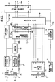
- Figure 1 is a structural diagram showing an absolute position encoder according to the present invention.
- a code plate is shown by reference numeral 1 in Figure 1, and the code plate 1 has a first track 1a with a code for a known incremental signal 2, a second track 1b with a code for a n-bit positional signal 3, and a third track 1c with a code corresponding to a m-bit positional signal 52 that is a detecting signal for the magnetic poles in an AC servo motor, and is provided in free rotation.
- a common plate is used practically.
- a first light source 4 a second light source 5, and a third light source 5A corresponding to respective tracks 1a, 1b, and 1c are provided individually.
- a light receiving section 6 for an incremental signal, a light receiving section 7 for an absolute position signal and a light receiving section 7A for a m-bit positional signal (composed of light receiving elements, the number of which corresponds to the m-bits) corresponding to said respective tracks 1a, 1b, and 1c are provided, and the light receiving section 7 for the absolute position signal is composed of a first light receiving section 7a to output a n-bit positional signal 3 and a second light receiving section 7b to output a n-bit positional signal 3A.
- Said incremental signal 2 and n-bit positional signal 3 are inputted to the latch circuit 10, and the incremental signal 2 is also inputted to an UP/DOWN circuit 11 connected to a counting circuit 12.
- Said latch circuit 10 is connected to a parallel signal convener 13 for conversion of a serial signal to a parallel signal, which is connected to said counting circuit 12 through a data selector 50.
- the parallel signal convener 13 is connected to a data selector 50 through a pure binary signal convener 100, and a parallel signal 13a is inputted to the data selector 50 after being convened to a pure binary signal 100a.
- the power ON signal 51 is inputted to the load command circuit 14, and a m-bit positional signal 52 (this is necessary to detect magnetic poles of the AC servo motor, and is used to drive the AC servo motor at power ON) obtained through the third track 1c for the m bits on said code plate 1 and a light receiving section for the m-bit positional signal is stored as the first load in the counting circuit 12 through the data selector 50.
- the AC servo motor (not shown) is minutely (360°/2 n ) rotated, the n-bit positional signal 3 is scanned and detected with the incremental signal 2 corresponding to these n bits, using the latch circuit 10, and the second load is performed setting this m-bit positional signal 52 as an absolute value against said counting circuit 12.
- the code plate 1 rotates with rotation of the AC servo motor, and this encoder makes the counting circuit 12 count up or down with the incremental signal 2 corresponding to said n-bit positional signal 3, can obtain an absolute signal 12A through adding the incremental signal 2 to the absolute value composed of the n-bit positional signal stored at the counting circuit in the above described second load, and can detect an input axis position of the AC servo motor.
- the initial starting can be performed with the m-bit positional signal 52 read from the third track 1c for the m bits having been recorded on the code plate 1 beforehand as a three-phase detecting signal (phases U, V, and W) of the magnetic poles for initially driving the AC servo motor.
- the input axis position of the AC servo motor can be obtained with the absolute signal 12A obtained from this absolute value and incremental signal 2.
- the signal processing system for processing the n-bit positional signal 3 becomes one circuit, it becomes not necessary to use n channels of signal processing systems as conventional, at the same time, the m-bit positional signal as the detecting signal of the magnetic poles in the AC servo motor can be obtained, and detection of the magnetic poles and detection of the speed and position of the AC servo motor can be performed.
- the AC servo motor can be immediately started up through regarding the m-bit positional signal obtained at power ON as the detecting signal of the magnetic poles.
- the signal processing system for processing the n-bit positional signal 3 becomes one series from the conventional n-channels, drastic hardware reduction can be attained.
- the absolute signal in good frequency characteristic can be obtained.
- the absolute value can be obtained from only the incremental signal on the basis of the absolute value having been loaded beforehand through having operated the counting circuit with the incremental signal.
- an absolute encoder for the AC servo motor can be obtained in the structure almost similar to an incremental encoder with the conventional detecting signal of the magnetic poles in the phases U, V and W.
Landscapes
- Physics & Mathematics (AREA)
- General Physics & Mathematics (AREA)
- Engineering & Computer Science (AREA)
- Theoretical Computer Science (AREA)
- Transmission And Conversion Of Sensor Element Output (AREA)
- Control Of Motors That Do Not Use Commutators (AREA)
- Analogue/Digital Conversion (AREA)
Claims (4)
- Absolutpositions-Codierverfahren, das von einem n-Bit-Positionssignal Gebrauch macht, das entlang einer ersten Spur (1b) einer Codeplatte (1) vorgesehen ist, und das von einem Inkrementsignal (2) Gebrauch macht, das Übergänge entsprechend der Teilung des n-Bit-Positionssignals (3) aufweist und entlang einer zweiten Spur der Codeplatte vorgesehen ist, wobei das Absolutpositions-Codierverfahren folgende Schritte aufweist:Vorsehen einer dritten Spur auf der Codeplatte, die ein m-Bit-Signal (52) enthält, wobei das m-Bit-Signal für die Magnetpolpositionen des Rotationselements eines Wechselstrom-Servomotors repräsentativ ist;Lesen des m-Bit-Signals zum Zeitpunkt des Einschaltens der Energieversorgung und Laden des gelesenen m-Bit-Signals in eine Zählschaltung;anschließendes Lesen des n-Bit-Positionssignals von der Codeplatte und Laden des gelesenen n-Bit-Positionssignals in die Zählschaltung (12); undInkrementieren oder Dekrementieren des geladenen n-Bit-Positionssignals in Abhängigkeit von Signalen, die von der Inkrementspur ausgelesen werden, um die codierte winkelmäßige Position des Rotationselements des Servomotors zu bestimmen.
- Absolutpositions-Codierverfahren nach Anspruch 1, mit folgenden weiteren Schritten:
Verwenden einer Zwischenspeicherschaltung (10) zum Lesen des n-Bit-Positionssignals (3) in denjenigen Momenten, in denen das Inkrementsignal seinen Wert ändert; und Laden des gelesenen n-Bit-Positionssignals durch einen Seriell-/Parallel-Signalwandler (13) in die Zählschaltung (12). - Absolutpositions-Codierverfahren nach Anspruch 1 oder Anspruch 2,
wobei die Zählschaltung (12) dazu veranlaßt wird, in Abhängigkeit von den Inkrementsignalen bei einer ersten Rotationsrichtung des Servomotors vorwärts zu zählen, sowie dazu veranlaßt wird, in Abhängigkeit von den Inkrementsignalen bei einer zweiten Rotationsrichtung des Servomotors rückwärts zu zählen. - Absolutpositions-Codierer zum Liefern eines Absolutsignals (12A) unter Verwendung eines n-Bit-Positionssignals (3), das auf einer Spur (1b) einer Codeplatte (1) ausgebildet ist, eines Inkrementsignals (2), das Übergänge entsprechend der Teilung des n-Bit-Positionssignals (3) aufweist und auf einer weiteren Spur der Codeplatte ausgebildet ist, sowie eines m-Bit-Signals, das die Magnetpolpositionen eines Rotationselements eines Wechselstrom-Servomotors repräsentiert und auf einer weiteren Spur der Codeplatte ausgebildet ist;
wobei der Codierer folgendes aufweist:eine Vorwärts-/Rückwärts-Schaltung (11), die einen mit einer Einrichtung zum Lesen des Inkrementsignals (2) gekoppelten Eingang aufweist,eine Zählschaltung (12), die einen mit einem Ausgang der Vorwärts-/Rückwärts-Schaltung (11) gekoppelten Eingang aufweist,eine Zwischenspeicherschaltung (10), die mit Einrichtungen zum Lesen des n-Bit-Positionssignals (3) und des Inkrementsignals (2) gekoppelte Eingänge aufweist,einen Seriell-/Parallel-Signalwandler, der einen mit einem Ausgang der Zwischenspeicherschaltung gekoppelten Eingang aufweist,einen reinen Binärsignalwandler (100) und eine Datenauswähleinrichtung (50), die zwischen einen Ausgang des Seriell-/Parallel-Signalwandlers und eine Eingangseinrichtung für die Zählschaltung geschaltet sind, sowieeine Ladebefehlsschaltung, die den reinen Binärsignalwandler und eine Quelle eines Energie-Einschalt-/Ausschaltsignals mit der Datenauswähleinrichtung und der Zählschaltung verbindet, um das Laden des m-Bit-Signals (52) in die Zählschaltung (12) zum Zeitpunkt des Einschaltens der Energieversorgung zu steuern.
Applications Claiming Priority (3)
| Application Number | Priority Date | Filing Date | Title |
|---|---|---|---|
| JP05928194A JP3410801B2 (ja) | 1994-03-29 | 1994-03-29 | アブソリュート信号検出方法及びアブソリュートエンコーダ |
| JP59281/94 | 1994-03-29 | ||
| JP5928194 | 1994-03-29 |
Publications (2)
| Publication Number | Publication Date |
|---|---|
| EP0675603A1 EP0675603A1 (de) | 1995-10-04 |
| EP0675603B1 true EP0675603B1 (de) | 2000-05-24 |
Family
ID=13108856
Family Applications (1)
| Application Number | Title | Priority Date | Filing Date |
|---|---|---|---|
| EP94309908A Expired - Lifetime EP0675603B1 (de) | 1994-03-29 | 1994-12-29 | Verfahren zur Detektierung eines Absolutpositionssignals und Absolutpositionsgeber |
Country Status (3)
| Country | Link |
|---|---|
| EP (1) | EP0675603B1 (de) |
| JP (1) | JP3410801B2 (de) |
| DE (1) | DE69424649T2 (de) |
Cited By (1)
| Publication number | Priority date | Publication date | Assignee | Title |
|---|---|---|---|---|
| CN101592468B (zh) * | 2009-06-25 | 2011-08-17 | 广州中国科学院工业技术研究院 | 伪随机码位移传感器的环形寻址方法及其系统 |
Families Citing this family (8)
| Publication number | Priority date | Publication date | Assignee | Title |
|---|---|---|---|---|
| JP3098732B2 (ja) * | 1997-09-11 | 2000-10-16 | 多摩川精機株式会社 | ディジタル角度変換方法 |
| DE50009018D1 (de) * | 1999-11-18 | 2005-01-27 | Hera Rotterdam Bv | Positionssensor |
| JP4375638B2 (ja) * | 2000-01-25 | 2009-12-02 | 株式会社ハーモニック・ドライブ・システムズ | モータ回転軸の絶対位置検出方法 |
| FR2845212B1 (fr) * | 2002-09-27 | 2005-03-18 | Roulements Soc Nouvelle | Dispositif de pilotage d'un moteur a commutation electronique au moyen d'un signal de position |
| FR2845213B1 (fr) * | 2002-09-27 | 2005-03-18 | Roulements Soc Nouvelle | Dispositif de pilotage d'un moteur a commutation electronique comprenant des singularites reparties angulairement |
| JP5273481B2 (ja) * | 2006-04-10 | 2013-08-28 | ティムケン ユーエス エルエルシー | 回動デバイス位置検知システムおよび方法 |
| JP6224349B2 (ja) * | 2013-05-15 | 2017-11-01 | 株式会社アイエイアイ | ステッピングモータ制御システム及びステッピングモータ制御方法 |
| CN106200561B (zh) * | 2016-07-31 | 2019-03-29 | 上海新时达电气股份有限公司 | 编码器控制器及配置方法 |
Family Cites Families (2)
| Publication number | Priority date | Publication date | Assignee | Title |
|---|---|---|---|---|
| US4736187A (en) * | 1986-12-04 | 1988-04-05 | The Regents Of The University Of California | Encoder for measuring both incremental and absolute positions of moving elements |
| JPH01116409A (ja) * | 1987-10-29 | 1989-05-09 | Fanuc Ltd | アブソリュート・ロータリ・エンコーダ |
-
1994
- 1994-03-29 JP JP05928194A patent/JP3410801B2/ja not_active Expired - Fee Related
- 1994-12-29 EP EP94309908A patent/EP0675603B1/de not_active Expired - Lifetime
- 1994-12-29 DE DE69424649T patent/DE69424649T2/de not_active Expired - Fee Related
Cited By (1)
| Publication number | Priority date | Publication date | Assignee | Title |
|---|---|---|---|---|
| CN101592468B (zh) * | 2009-06-25 | 2011-08-17 | 广州中国科学院工业技术研究院 | 伪随机码位移传感器的环形寻址方法及其系统 |
Also Published As
| Publication number | Publication date |
|---|---|
| JP3410801B2 (ja) | 2003-05-26 |
| EP0675603A1 (de) | 1995-10-04 |
| DE69424649T2 (de) | 2001-02-08 |
| JPH07270181A (ja) | 1995-10-20 |
| DE69424649D1 (de) | 2000-06-29 |
Similar Documents
| Publication | Publication Date | Title |
|---|---|---|
| EP0675603B1 (de) | Verfahren zur Detektierung eines Absolutpositionssignals und Absolutpositionsgeber | |
| JP3179493B2 (ja) | アブソリュートエンコーダ | |
| EP0502534B1 (de) | Kodierer | |
| EP0590605B1 (de) | Halb-flash A/D-Wandler und A/D-Wandlungsverfahren | |
| JPWO1993021499A1 (ja) | アブソリュートエンコーダ | |
| US5117105A (en) | Absolute encoder | |
| EP0766405A1 (de) | Register mit schrittweiser Annäherung ohne Redundanz | |
| EP0318597A1 (de) | Kodierer der absoluten position | |
| US6100823A (en) | Single sensor position encoder providing two levels of resolution | |
| US5774068A (en) | Absolute signal detecting method and absolute encoder | |
| EP0680150B1 (de) | Verfahren zur Dekodierung einer Absolutposition und Absolutpositionsgeber | |
| US5231596A (en) | Position detector having a single set detector for absolute codes | |
| EP0341945B1 (de) | Interfacecodiereinrichtung für Wellenwinkel | |
| JP3171485B2 (ja) | 高分解能アブソリュート信号の作成方法 | |
| US5122980A (en) | Encoder interpolator circuit | |
| JPH02104024A (ja) | 逐次比較型アナログ・デジタル変換器 | |
| JP3724518B2 (ja) | アブソリュートエンコーダ | |
| JP2796614B2 (ja) | データ再生方法及びその実施に用いる装置 | |
| SU1432719A1 (ru) | Четырехтактный реверсивный распределитель импульсов дл управлени шаговым двигателем | |
| JP3273836B2 (ja) | エンコーダ信号出力方法 | |
| JP3033297B2 (ja) | 多回転アブソリュートエンコーダ | |
| JP3273837B2 (ja) | エンコーダ信号出力方法 | |
| JP2000314639A (ja) | Acサーボモータ用エンコーダ | |
| JPH0336236Y2 (de) | ||
| JPH0775372A (ja) | エンコーダ信号出力方法 |
Legal Events
| Date | Code | Title | Description |
|---|---|---|---|
| PUAI | Public reference made under article 153(3) epc to a published international application that has entered the european phase |
Free format text: ORIGINAL CODE: 0009012 |
|
| AK | Designated contracting states |
Kind code of ref document: A1 Designated state(s): DE FR GB IT SE |
|
| 17P | Request for examination filed |
Effective date: 19951107 |
|
| 17Q | First examination report despatched |
Effective date: 19980515 |
|
| GRAG | Despatch of communication of intention to grant |
Free format text: ORIGINAL CODE: EPIDOS AGRA |
|
| RTI1 | Title (correction) |
Free format text: ABSOLUTE POSITION ENCODING METHOD AND ABSOLUTE POSITION ENCODER |
|
| GRAG | Despatch of communication of intention to grant |
Free format text: ORIGINAL CODE: EPIDOS AGRA |
|
| GRAH | Despatch of communication of intention to grant a patent |
Free format text: ORIGINAL CODE: EPIDOS IGRA |
|
| GRAH | Despatch of communication of intention to grant a patent |
Free format text: ORIGINAL CODE: EPIDOS IGRA |
|
| GRAA | (expected) grant |
Free format text: ORIGINAL CODE: 0009210 |
|
| AK | Designated contracting states |
Kind code of ref document: B1 Designated state(s): DE FR GB IT SE |
|
| ITF | It: translation for a ep patent filed | ||
| REF | Corresponds to: |
Ref document number: 69424649 Country of ref document: DE Date of ref document: 20000629 |
|
| ET | Fr: translation filed | ||
| PLBE | No opposition filed within time limit |
Free format text: ORIGINAL CODE: 0009261 |
|
| STAA | Information on the status of an ep patent application or granted ep patent |
Free format text: STATUS: NO OPPOSITION FILED WITHIN TIME LIMIT |
|
| 26N | No opposition filed | ||
| REG | Reference to a national code |
Ref country code: GB Ref legal event code: IF02 |
|
| PGFP | Annual fee paid to national office [announced via postgrant information from national office to epo] |
Ref country code: SE Payment date: 20031204 Year of fee payment: 10 |
|
| PGFP | Annual fee paid to national office [announced via postgrant information from national office to epo] |
Ref country code: FR Payment date: 20031210 Year of fee payment: 10 |
|
| PGFP | Annual fee paid to national office [announced via postgrant information from national office to epo] |
Ref country code: GB Payment date: 20031224 Year of fee payment: 10 |
|
| PGFP | Annual fee paid to national office [announced via postgrant information from national office to epo] |
Ref country code: DE Payment date: 20040108 Year of fee payment: 10 |
|
| PG25 | Lapsed in a contracting state [announced via postgrant information from national office to epo] |
Ref country code: GB Free format text: LAPSE BECAUSE OF NON-PAYMENT OF DUE FEES Effective date: 20041229 |
|
| PG25 | Lapsed in a contracting state [announced via postgrant information from national office to epo] |
Ref country code: SE Free format text: LAPSE BECAUSE OF NON-PAYMENT OF DUE FEES Effective date: 20041230 |
|
| PG25 | Lapsed in a contracting state [announced via postgrant information from national office to epo] |
Ref country code: DE Free format text: LAPSE BECAUSE OF NON-PAYMENT OF DUE FEES Effective date: 20050701 |
|
| EUG | Se: european patent has lapsed | ||
| GBPC | Gb: european patent ceased through non-payment of renewal fee |
Effective date: 20041229 |
|
| PG25 | Lapsed in a contracting state [announced via postgrant information from national office to epo] |
Ref country code: FR Free format text: LAPSE BECAUSE OF NON-PAYMENT OF DUE FEES Effective date: 20050831 |
|
| REG | Reference to a national code |
Ref country code: FR Ref legal event code: ST |
|
| PG25 | Lapsed in a contracting state [announced via postgrant information from national office to epo] |
Ref country code: IT Free format text: LAPSE BECAUSE OF NON-PAYMENT OF DUE FEES;WARNING: LAPSES OF ITALIAN PATENTS WITH EFFECTIVE DATE BEFORE 2007 MAY HAVE OCCURRED AT ANY TIME BEFORE 2007. THE CORRECT EFFECTIVE DATE MAY BE DIFFERENT FROM THE ONE RECORDED. Effective date: 20051229 |